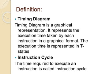
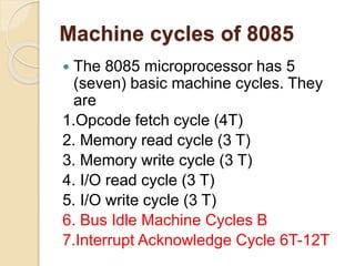
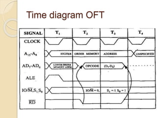
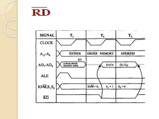
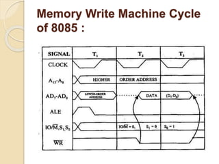
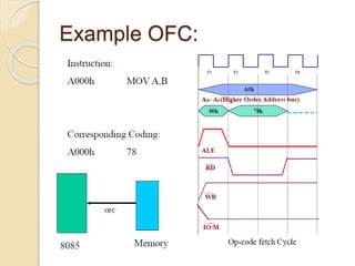
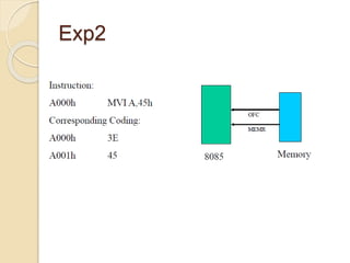
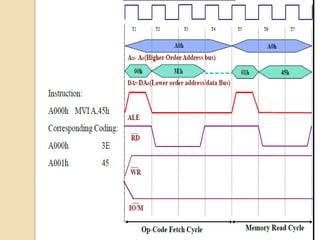
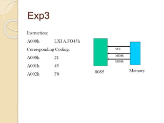
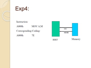
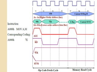
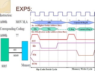
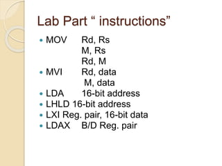
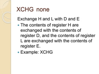
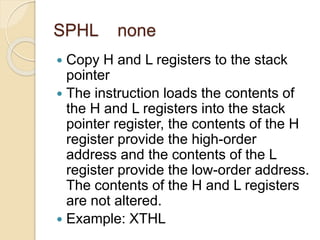
Timing Diagram & Machine
Cycles
Wafa Abied
Definition:
 Timing Diagram
Timing Diagram is a graphical
representation. It represents the
execution time taken by each
instruction in a graphical format. The
execution time is represented in T-
states
 Instruction Cycle
The time required to execute an
instruction is called instruction cycle
Definition:
 Machine Cycle
The time required to access the
memory or input/output devices is
called machine cycle.
 T-State
The machine cycle and instruction cycle
takes multiple clock periods.
A portion of an operation carried out in
one system clock period is called as
T-state
Machine cycles of 8085
 The 8085 microprocessor has 5
(seven) basic machine cycles. They
are
1.Opcode fetch cycle (4T)
2. Memory read cycle (3 T)
3. Memory write cycle (3 T)
4. I/O read cycle (3 T)
5. I/O write cycle (3 T)
6. Bus Idle Machine Cycles B
7.Interrupt Acknowledge Cycle 6T-12T
Clock Signal
Opcode fetch machine cycle of
8085:
 Each instruction of the processor has one byte
opcode.
 The opcodes are stored in memory. So, the
processor executes the opcode fetch machine
cycle to fetch the opcode from memory.
 Hence, every instruction starts with opcode fetch
machine cycle.
 The time taken by the processor to execute the
opcode fetch cycle is 4T.
 In this time, the first, 3 T-states are used for
fetching the opcode from memory and the
remaining T-states are used for internal
operations by the processor.
Time diagram OFT
Memory Read Machine Cycle
of 8085:
 The memory read machine cycle is
executed by the processor to read a
data byte from memory.
 The processor takes 3T states to
execute this cycle.
 The instructions which have more than
one byte word size will use the machine
cycle after the opcode fetch machine
cycle.
RDRDRDRD
Memory Write Machine Cycle
of 8085 :
 The memory write machine cycle is
executed by the processor to write a
data byte in a memory location.
 The processor takes, 3T states to
execute this machine cycle.
Memory Write Machine Cycle
of 8085 :
I/O Read Cycle of 8085
 The I/O Read cycle is executed by the
processor to read a data byte from I/O
port or from the peripheral, which is
I/O, mapped in the system.
 The processor takes 3T states to
execute this machine cycle.
 The IN instruction uses this machine
cycle during the execution
Example OFC:
Exp2
Exp3
Exp4:
EXP5:
H.W:
1. Draw timing diagram for STA 546AH ?
2. Draw timing diagram for INR M ? Let the
memory address (M) be 4250H and the memory
content is 12H?
STAX Reg. pair
 The contents of the accumulator are
copied into the memory location
specified by the contents of the operand
(register pair).
 The contents of the accumulator are not
altered.
 Example: STAX B
Lab Part “ instructions”
 MOV Rd, Rs
M, Rs
Rd, M
 MVI Rd, data
M, data
 LDA 16-bit address
 LHLD 16-bit address
 LXI Reg. pair, 16-bit data
 LDAX B/D Reg. pair
XCHG none
Exchange H and L with D and E
 The contents of register H are
exchanged with the contents of
register D, and the contents of register
L are exchanged with the contents of
register E.
 Example: XCHG
SPHL none
 Copy H and L registers to the stack
pointer
 The instruction loads the contents of
the H and L registers into the stack
pointer register, the contents of the H
register provide the high-order
address and the contents of the L
register provide the low-order address.
The contents of the H and L registers
are not altered.
 Example: XTHL
XTHL none
 Exchange H and L with top of stack
 The contents of the L register are
exchanged with the stack location
pointed out by the contents of the
stack pointer register. The contents of
the H register are exchanged with the
next stack location (SP+1); however,
the contents of the stack pointer
register are not altered.
 Example: XTHL
 DAD instruction adds the contents (16bit) of
the specified register pair with that of HL pair.
 This instruction takes 10 T states including
opcode fetch.
 The opcode fetch cycle takes 4 T states and
the remaining 6 T states, divided into two
machine cycles, are for the instruction
execution.
 During these 6 T (two machine cycles) states
no bus operations are performed.
 Hence they are called bus idle machine
cycles. During this ALE, RD etc are not
activated.

Machine cycles

  • 1.
    Timing Diagram &Machine Cycles Wafa Abied
  • 2.
    Definition:  Timing Diagram TimingDiagram is a graphical representation. It represents the execution time taken by each instruction in a graphical format. The execution time is represented in T- states  Instruction Cycle The time required to execute an instruction is called instruction cycle
  • 3.
    Definition:  Machine Cycle Thetime required to access the memory or input/output devices is called machine cycle.  T-State The machine cycle and instruction cycle takes multiple clock periods. A portion of an operation carried out in one system clock period is called as T-state
  • 4.
    Machine cycles of8085  The 8085 microprocessor has 5 (seven) basic machine cycles. They are 1.Opcode fetch cycle (4T) 2. Memory read cycle (3 T) 3. Memory write cycle (3 T) 4. I/O read cycle (3 T) 5. I/O write cycle (3 T) 6. Bus Idle Machine Cycles B 7.Interrupt Acknowledge Cycle 6T-12T
  • 5.
  • 6.
    Opcode fetch machinecycle of 8085:  Each instruction of the processor has one byte opcode.  The opcodes are stored in memory. So, the processor executes the opcode fetch machine cycle to fetch the opcode from memory.  Hence, every instruction starts with opcode fetch machine cycle.  The time taken by the processor to execute the opcode fetch cycle is 4T.  In this time, the first, 3 T-states are used for fetching the opcode from memory and the remaining T-states are used for internal operations by the processor.
  • 7.
  • 8.
    Memory Read MachineCycle of 8085:  The memory read machine cycle is executed by the processor to read a data byte from memory.  The processor takes 3T states to execute this cycle.  The instructions which have more than one byte word size will use the machine cycle after the opcode fetch machine cycle.
  • 9.
  • 10.
    Memory Write MachineCycle of 8085 :  The memory write machine cycle is executed by the processor to write a data byte in a memory location.  The processor takes, 3T states to execute this machine cycle.
  • 11.
    Memory Write MachineCycle of 8085 :
  • 12.
    I/O Read Cycleof 8085  The I/O Read cycle is executed by the processor to read a data byte from I/O port or from the peripheral, which is I/O, mapped in the system.  The processor takes 3T states to execute this machine cycle.  The IN instruction uses this machine cycle during the execution
  • 13.
  • 14.
  • 16.
  • 18.
  • 20.
  • 21.
    H.W: 1. Draw timingdiagram for STA 546AH ? 2. Draw timing diagram for INR M ? Let the memory address (M) be 4250H and the memory content is 12H?
  • 22.
    STAX Reg. pair The contents of the accumulator are copied into the memory location specified by the contents of the operand (register pair).  The contents of the accumulator are not altered.  Example: STAX B
  • 23.
    Lab Part “instructions”  MOV Rd, Rs M, Rs Rd, M  MVI Rd, data M, data  LDA 16-bit address  LHLD 16-bit address  LXI Reg. pair, 16-bit data  LDAX B/D Reg. pair
  • 25.
    XCHG none Exchange Hand L with D and E  The contents of register H are exchanged with the contents of register D, and the contents of register L are exchanged with the contents of register E.  Example: XCHG
  • 26.
    SPHL none  CopyH and L registers to the stack pointer  The instruction loads the contents of the H and L registers into the stack pointer register, the contents of the H register provide the high-order address and the contents of the L register provide the low-order address. The contents of the H and L registers are not altered.  Example: XTHL
  • 27.
    XTHL none  ExchangeH and L with top of stack  The contents of the L register are exchanged with the stack location pointed out by the contents of the stack pointer register. The contents of the H register are exchanged with the next stack location (SP+1); however, the contents of the stack pointer register are not altered.  Example: XTHL
  • 28.
     DAD instructionadds the contents (16bit) of the specified register pair with that of HL pair.  This instruction takes 10 T states including opcode fetch.  The opcode fetch cycle takes 4 T states and the remaining 6 T states, divided into two machine cycles, are for the instruction execution.  During these 6 T (two machine cycles) states no bus operations are performed.  Hence they are called bus idle machine cycles. During this ALE, RD etc are not activated.