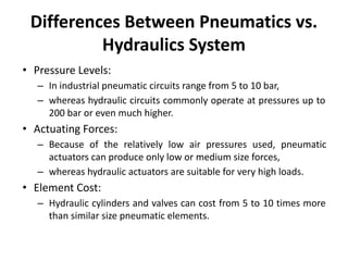
1. Hydraulic systems typically operate at higher pressures than pneumatic systems and are suitable for very high loads, while pneumatic systems are generally used for lower pressures and forces.
2. Hydraulic components like cylinders and valves tend to be more expensive than similar pneumatic components.
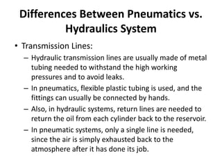
3. Pneumatic systems use compressed air and flexible tubing, while hydraulic systems use pressurized liquids and metal tubing to withstand higher pressures.