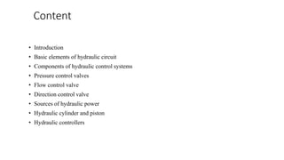
Hydraulic Valves and Hydraulic System AccessoriesRAHUL THAKER
Hydraulic Valves and Hydraulic System Accessories:
Direction control valves,Pressure control valves, Flow control valves, Non-return valves, Reservoirs,Accumulators, Heating & cooling devices, Hoses. Selection of valves for circuits.
Hydraulic Valves and Hydraulic System AccessoriesRAHUL THAKER
Hydraulic Valves and Hydraulic System Accessories:
Direction control valves,Pressure control valves, Flow control valves, Non-return valves, Reservoirs,Accumulators, Heating & cooling devices, Hoses. Selection of valves for circuits.
A pneumatic control valve actuator converts energy (typically in the form of compressed air) into mechanical motion. The motion can be rotary or linear, depending on the type of actuator.
Hydraulics is a branch of science which deals with hydraulic fluid. It is used in places where cleanliness is not a priority but requires huge power to perform tasks.
application:
1. Industrial: Plastic processing machineries, steel making and primary metal extraction applications, automated production lines, machine tool industries, paper industries, loaders, crushes, textile machineries, R & D equipment and robotic systems etc.
2 Mobile hydraulics: Tractors, irrigation system, earthmoving equipment, material handling equipment, commercial vehicles, tunnel boring equipment, rail equipment, building and construction machineries and drilling rigs etc.
3 Automobiles: It is used in the systems like breaks, shock absorbers, steering system, wind shield, lift and cleaning etc.
4 Marine applications: It mostly covers ocean going vessels, fishing boats and navel equipment.
5 Aerospace equipment: There are equipment and systems used for rudder control, landing gear, breaks, flight control and transmission etc. which are used in airplanes, rockets and spaceships.
Properties of air – Perfect Gas Laws – Compressor – Filters, Regulator, Lubricator, Muffler, Air
control Valves, Quick Exhaust Valves, Pneumatic actuators, Design of Pneumatic circuit – Cascade method – Electro Pneumatic System – Elements – Ladder diagram – Problems,
Introduction to fluidics and pneumatic logic
Hydraulic Filters are used to keep the contaminants away from the system and avoid mechanical failures. Fleetguard products cater to high, low and medium pressure hydraulic systems to protect industrial machinery and equipments.
For more details visit: https://www.fleetguard-filtrum.com/products/hydraulic-filtration/
Hydraulics today has become a way of life as most applications have some form of system ingrained. This paper is an endevor to present the very basics of hydraulics and overcome its basic fear.
Pneumatic Drives-Hydraulic Drives-Mechanical Drives-Electrical Drives-D.C. Servo Motors, Stepper Motors, A.C. Servo Motors-Salient Features, Applications and Comparison of all these Drives, End Effectors-Grippers-Mechanical Grippers, Pneumatic and Hydraulic- Grippers, Magnetic Grippers, Vacuum Grippers; Two Fingered and Three Fingered Grippers; Internal Grippers and External Grippers; Selection and Design Considerations.
Module 5 hydraulics and pneumatics Actuation systemstaruian
Pneumatic and hydraulic actuation systems: Pneumatic and hydraulic systems actuating systems.
Classifications of Valves: Pressure relief valves, Pressure regulating / reducing valves
Cylinders and rotary actuators.
DCV & FCV: Principle & construction details.
Types of sliding spool valve & solenoid operated.
Symbols of hydraulic elements, components of hydraulic system, functions of various units of hydraulic system.
Design of simple hydraulic circuits for various applications
HYDRAULIC POWER GENERATING AND UTILIZING SYSTEMS
Introduction to fluid power system - Hydraulic fluids - functions, types, properties, selection and application.
POWER GENERATING ELEMENTS: Pumps, classification, working of different pumps such as Gear, Vane, Piston (axial and radial), pump performance or characteristics, pump selection factors- simple Problems.
POWER UTILIZING ELEMENTS: Fluid Power Actuators: Linear hydraulic actuators – Types and construction of hydraulic cylinders – Single acting, Double acting, special cylinders like tandem, Rodless, Telescopic, Cushioning mechanism.
Hydraulic Motors, types – Gear, Vane, Piston (axial and radial) – performance of motors.
A control valve is a power-operated device used to regulate or manipulate the flow of fluids, such as gas, oil, water, and steam. It is a critical part of a control loop and is an example of a final control element.
Forklift Classes Overview by Intella PartsIntella Parts
Discover the different forklift classes and their specific applications. Learn how to choose the right forklift for your needs to ensure safety, efficiency, and compliance in your operations.
For more technical information, visit our website https://intellaparts.com
Water scarcity is the lack of fresh water resources to meet the standard water demand. There are two type of water scarcity. One is physical. The other is economic water scarcity.
TECHNICAL TRAINING MANUAL GENERAL FAMILIARIZATION COURSEDuvanRamosGarzon1
AIRCRAFT GENERAL
The Single Aisle is the most advanced family aircraft in service today, with fly-by-wire flight controls.
The A318, A319, A320 and A321 are twin-engine subsonic medium range aircraft.
The family offers a choice of engines
Overview of the fundamental roles in Hydropower generation and the components involved in wider Electrical Engineering.
This paper presents the design and construction of hydroelectric dams from the hydrologist’s survey of the valley before construction, all aspects and involved disciplines, fluid dynamics, structural engineering, generation and mains frequency regulation to the very transmission of power through the network in the United Kingdom.
Author: Robbie Edward Sayers
Collaborators and co editors: Charlie Sims and Connor Healey.
(C) 2024 Robbie E. Sayers
Explore the innovative world of trenchless pipe repair with our comprehensive guide, "The Benefits and Techniques of Trenchless Pipe Repair." This document delves into the modern methods of repairing underground pipes without the need for extensive excavation, highlighting the numerous advantages and the latest techniques used in the industry.
Learn about the cost savings, reduced environmental impact, and minimal disruption associated with trenchless technology. Discover detailed explanations of popular techniques such as pipe bursting, cured-in-place pipe (CIPP) lining, and directional drilling. Understand how these methods can be applied to various types of infrastructure, from residential plumbing to large-scale municipal systems.
Ideal for homeowners, contractors, engineers, and anyone interested in modern plumbing solutions, this guide provides valuable insights into why trenchless pipe repair is becoming the preferred choice for pipe rehabilitation. Stay informed about the latest advancements and best practices in the field.
Student information management system project report ii.pdfKamal Acharya
Our project explains about the student management. This project mainly explains the various actions related to student details. This project shows some ease in adding, editing and deleting the student details. It also provides a less time consuming process for viewing, adding, editing and deleting the marks of the students.
Democratizing Fuzzing at Scale by Abhishek Aryaabh.arya
Presented at NUS: Fuzzing and Software Security Summer School 2024
This keynote talks about the democratization of fuzzing at scale, highlighting the collaboration between open source communities, academia, and industry to advance the field of fuzzing. It delves into the history of fuzzing, the development of scalable fuzzing platforms, and the empowerment of community-driven research. The talk will further discuss recent advancements leveraging AI/ML and offer insights into the future evolution of the fuzzing landscape.
NO1 Uk best vashikaran specialist in delhi vashikaran baba near me online vas...Amil Baba Dawood bangali
Contact with Dawood Bhai Just call on +92322-6382012 and we'll help you. We'll solve all your problems within 12 to 24 hours and with 101% guarantee and with astrology systematic. If you want to take any personal or professional advice then also you can call us on +92322-6382012 , ONLINE LOVE PROBLEM & Other all types of Daily Life Problem's.Then CALL or WHATSAPP us on +92322-6382012 and Get all these problems solutions here by Amil Baba DAWOOD BANGALI
#vashikaranspecialist #astrologer #palmistry #amliyaat #taweez #manpasandshadi #horoscope #spiritual #lovelife #lovespell #marriagespell#aamilbabainpakistan #amilbabainkarachi #powerfullblackmagicspell #kalajadumantarspecialist #realamilbaba #AmilbabainPakistan #astrologerincanada #astrologerindubai #lovespellsmaster #kalajaduspecialist #lovespellsthatwork #aamilbabainlahore#blackmagicformarriage #aamilbaba #kalajadu #kalailam #taweez #wazifaexpert #jadumantar #vashikaranspecialist #astrologer #palmistry #amliyaat #taweez #manpasandshadi #horoscope #spiritual #lovelife #lovespell #marriagespell#aamilbabainpakistan #amilbabainkarachi #powerfullblackmagicspell #kalajadumantarspecialist #realamilbaba #AmilbabainPakistan #astrologerincanada #astrologerindubai #lovespellsmaster #kalajaduspecialist #lovespellsthatwork #aamilbabainlahore #blackmagicforlove #blackmagicformarriage #aamilbaba #kalajadu #kalailam #taweez #wazifaexpert #jadumantar #vashikaranspecialist #astrologer #palmistry #amliyaat #taweez #manpasandshadi #horoscope #spiritual #lovelife #lovespell #marriagespell#aamilbabainpakistan #amilbabainkarachi #powerfullblackmagicspell #kalajadumantarspecialist #realamilbaba #AmilbabainPakistan #astrologerincanada #astrologerindubai #lovespellsmaster #kalajaduspecialist #lovespellsthatwork #aamilbabainlahore #Amilbabainuk #amilbabainspain #amilbabaindubai #Amilbabainnorway #amilbabainkrachi #amilbabainlahore #amilbabaingujranwalan #amilbabainislamabad
Sachpazis:Terzaghi Bearing Capacity Estimation in simple terms with Calculati...Dr.Costas Sachpazis
Terzaghi's soil bearing capacity theory, developed by Karl Terzaghi, is a fundamental principle in geotechnical engineering used to determine the bearing capacity of shallow foundations. This theory provides a method to calculate the ultimate bearing capacity of soil, which is the maximum load per unit area that the soil can support without undergoing shear failure. The Calculation HTML Code included.
1. Presentation on hydraulic
control systems
CONTROL ENGINEERING (2151908)
NAME:- Vadgama sumit himmatbhai
ENROLLMENT NO:- 180053119059
guided by -NIRMAL KUSHWAHA SIR
2. Content
• Introduction
• Basic elements of hydraulic circuit
• Components of hydraulic control systems
• Pressure control valves
• Flow control valve
• Direction control valve
• Sources of hydraulic power
• Hydraulic cylinder and piston
• Hydraulic controllers
3. Introduction
• Before going into the advantages of fluid power system, it is essential
to discuss the principle and the functions of hydraulic system.
• The systematic layout of hydraulic system is shown in fig.1 in this a
prime mover supplies the mechanical energy to a pump which is used
to pressurise a fluid. Therefore the mechanical energy supplied by the
prime mover is converted into pressure energy by the pump and it is
stored in fluid.
5. •The major components are
• Prime mover
• Pump
• Control valves
• Actuators
• Piping system
• Fluid
6. Few supporting components are:
• Filters
• Strainers
• Storage tank
• Heat exchangers
• Pressure gauges
• Sensors
• Protective devices
• Control devices
7. Prime mover
• It is the device which develops the mechanical power. It is a
power producing device. The type of prime mover will
depend on the system. After passing through fluid power
system this power is again available as mechanical power.
8. pump
• Hydraulic pumps are used in hydraulic drive systems and can be
hydrostatic or hydrodynamic.
• A hydraulic pump is a mechanical source of power that converts
mechanical power into hydraulic energy (hydrostatic energy i.e. flow,
pressure).
• It generates flow with enough power to overcome pressure induced by
the load at the pump outlet. When a hydraulic pump operates, it
creates a vacuum at the pump inlet, which forces liquid from the
reservoir into the inlet line to the pump and by mechanical action
delivers this liquid to the pump outlet and forces it into the hydraulic
system.
9. Control valves
• The pressurised fluid supplied by the pump is required to diverted to
various parts of the system.
• Also controls various parameter of flowing fluid. • Classified into
three types:
• 1.Pressure control valves
• 2.Flow control valves
• 3.Direction control valves
• 4. As name suggests , these valves control the respective parameter of
fluid.
10. Actuators
• Actuators convert the fluid power contained in pressurized fluid to
mechanical energy. They are the muscles of the system. • They provide
the mechanical motion to the desired part and the desired actuating
force. • The actuators can be divided into linear and rotary actuators. •
Example of linear actuators is single acting cylinders and rotary
actuator is limited rotation motor.
11. Piping system
• They carry fluid containing the energy to various parts of system. •
After transmitting energy, the return oil is brought back to the
reservoir. • Due to the high pressure involved, design of piping system
require extreme care. • Bursting of piping could prove to be a serious
matter leading to damage of equipment or injury to personnel.
12. Filters:
• Hydraulic filters remove dirt and particles from fluid in a hydraulic
system.
• A hydraulic filter helps to remove these particles and clean the oil on
a continuous basis. The performance for every hydraulic filter is
measured by its contamination removal efficiency, i.e. high dirt-
holding capacities. Almost every hydraulic system contains more than
one hydraulic filter.
13. Accumulators
• These are storage devices. They can cater for small time fluctuations
in the energy. This may be due to power failures. They provide a small
pool of pressurized oil which can be used during emergencies.
14. Electrical devices
• They provide much flexibility in operation.
• • They are used in control of fluid power. Electrical control
enables us the remote operation, automation and sequencing.
Some of the electrical components include solenoids, torque
motors, and limit switchers.
15. Measuring gauges
• In addition to the various functional components mentioned there is a
need to measure certain parameters for monitoring the proper
functioning of the system.
• For this a fluid power system incorporates a number of measuring
gauges e.g. pressure gauge, temperature gauges, position sensor etc.
these are basically safety devices.
16. Pressure-control valves
• Pressure-control valves are found in virtually every hydraulic system,
and they assist in a variety of functions, from keeping system
pressures safely below a desired upper limit to maintaining a set
pressure in part of a circuit.
• Types include relief, reducing, sequence, counterbalance, and
unloading. All of these are normally closed valves, except for reducing
valves, which are normally open. For most of these valves, a
restriction is necessary to produce the required pressure control. One
exception is the externally piloted unloading valve, which depends on
an external signal for its actuation
17. Pressure relief valves
• Most fluid power systems are designed to operate within a present
pressure range. This range is a function of the forces the actuators in
the system must generate to do the required work. Without controlling
or limiting these forces, the fluid power components (and expensive
equipment) could be damaged. Relief valves avoid this hazard. They
are the safeguards which limit maximum pressure in a system by
diverting excess oil when pressures get too high.
18.
19. Flow control valves
• Flow control valves manage the flow by decreasing or increasing
the opening at the throttling point. This helps to determine speed
of movement for the actuators. The simplest design for a flow
control valve is a needle or longitudinal slot mounted in the
pipeline and connected to a screw that adjusts the opening at the
throttling point.
• These are called throttle valves and they are regularly used in
combination with a check valve, i.e. the throttle check valve for
speed control in one direction of flow. A disadvantage of throttle
valves is that at varying loads a change in pressure drop will
change the flow; thus, the speed of the moving actuator will also
be affected.
20. Classification of flow control valves
• 1. Needle valves : Needle controls the area of orifice , which
causes change in flow rate through the valve.
• 2. Globe valves : Controlling element is disc or globe.
• 3. Gate valves : Flow control achieved by the movement of
the gate
21.
22. Direction control valves
• Direction control valve is used for distribution of energy to
various actuators by controlling the direction of flow of the
pressurized oil in system. Therfore, it has the direct influence
on start, stop and the flow direction of the actuators
24. Sources of hydraulic power
• In fluid power actuators are those devices which convert the fluid
power into the mechanical power at desired place. They produce
the required working force and provide the necessary type of
motion.
• By using the actuator we are able to get the motion in any
convenient form. By using the hydraulic actuators we can generate
and apply large quantum of forces.
25. Classification of actuators
Depending upon the nature of motion given by the actuator, they can be
classied as:
1. Linear actuators : To provide linear motion as output
2. Rotary actuators :To provide rotary motion as the output
27. Piston pump
• In piston pumps the pumping action is caused by reciprocation of
an element called piston.
• The reciprocating action is caused by special cam arrangement.
• The cylinder may be arrangement in a number of ways.
28. Bent axis type axial piston pumps
• The arrangement of cylinder and piston is shown in fig. the
cylinder block is connected to the driven shaft through a
universal joint. The cylinder block is given inclination α to the
direction of the drive shaft.
• Pistons are inserted into each of the cylinder.
29. Swash plate type of axial piston pump
• a swash plate is basically a wedge cam. To visualise this consider
a cylinder which is given cut at angle α across aixs. The cut face
of the swash plate resembles a wedge cam as shown in fig.
• Pumping action of the piston pump is produced by the swash
plate.when the cylinder blocks rotates with the pistons inside the
cylinders the free end of the pistion rub against the swash plate.
• Due to the inclination of the swash plate the free ends of the
pistions will be pushed in and out of the cylinder there by causing
a reciprocating motion.
30.
31. Radial pistion pumps
• in this type of pumps the cylinders are arranged around the
periphery of circular cylinder block. The arrangement is shown in
fig.
• The essential components of radial piston pump are:
-cylinder block -piston -track ring -inlet and outlet port
32. vane pumps
• Vane pump are also known as sliding vane pump. The basic
components of a vane pump are
1. Rotor with radial slot
2. Sliding vane
3. Casing
4. ports
33. gear pump
• Gear pump is positive displacement pump used in hydraulic
system.
• It can developed high pressure at low discharge.
• It is simpe in design, cheap and it can handle a variety of fluids,
e.g. petroleum oil, synthetic oil and water based emulsions
34.
35. Screw pump
• The action of screw pump is similer to the gear pump.
• However the difference between the two is that in case of gear pumps gear
teeth mesh while in screw pump the screw mesh to develop the desired
pressure.
• When the screws mesh they from fluid tight seal between the screw and
casing. One of the screw can be connected to the drive shaft nd other could
run as the follower or the both the shaft could be given drive separately.
36. Advantages of screw pumps
• Wide range of flow and pressure.
• Wide range of liquids can be handled.
• Low internal velocity.
• Low vibration and noise.
• High speed capability.
37. Hydraulic cylinders
• Hydraulic cylinders are linear actuators which provide linear motion
and force. They can develop very large quantum of force and very
long strokes obtained through cylinders
• Hydraulic cylinders could be classified into two broad categories as:
1. Sinle acting.
2. Double acting.
38. Single acting cylinder
• A single acting cylinder is shown in fig.
• The pressurised fluid is supplied from the pump through the
control valves. It can enter into the cylinder through a port
provided at the piston end of the cylinder.
• When oil under pressures enters the cylinder through the inlet port
it pushes the piston forward.
• after reaching the forward most position the return motion is due
to a spring force. The oil moves out of the cylinder through the
same port to the tank.
39.
40. Double acting cylinder
• The double acting cylinder is shown in fig.
• It has two ports. Port A at the rod end and port B at the end of the
piston end.
• For the forward motion of the piston pressurised oil enters through
port A and pushes the piston forwards.
• For the return motion oil enters through port B and pushes the piston
backwards.
41. Hydraulic proportional controller
• It basically consists of a pilot valve and single ating hydraulic
cylinder. The error signal is given t the pilot valve through the
input link. The controller output is obtained from the single acting
cylinder through the output link. It could be seen that the output
link is connected to the input link through a feedback link.
42. Hydraulic integral controller
• The components are similar to that of proportional control. But the
pilot valve in this case can divert the oil to ports. Each going to
each side of a double acting cylinder.
43. • In double acting cylinder the motion to both sides are controlled
by oil flow.
• The input and feedback link are same. If an error input e is given
to the input link it moves the spool of the pilot valve. Oil would be
send to the corresponding port of the double acting cylinder when
pressurised oil goes to double acting cylinder it moves the piston
to one side.
• This movement of the piston is feedback to the feedback link thus
an output motion of the cylinder is produced corresponding to the
error input
• Q α e
44. Hydraulic crane
• Hydraulic cranes are used to lift heavy weights and place them at
a higher or lower level. This is used in all types of material
handling applications such as docks, harbours, factories,
construction sites etc. the basic construction is shown in fig.
45. • Components
• 1. structure
• 2. Tie
• 3. Jib
• 4. Fixed pulley and movable pulley
48. Hydraulic system
• Working fluid is a liquid
• Works at high pressure
• Working fluid is
incompressible
• Very high working force
could be developed.
• System is more compact.
• self lubricating effects.
• Heavy tube and pipes are
required
Pneumatic system
• Working fluid is a gas
• Work at low pressure
• Working fluid is compressible
• Moderate force only could
be developed.
• It is more bulky
• No self lubricating effects
• Light tube and pipes are
required