Downloaded 790 times


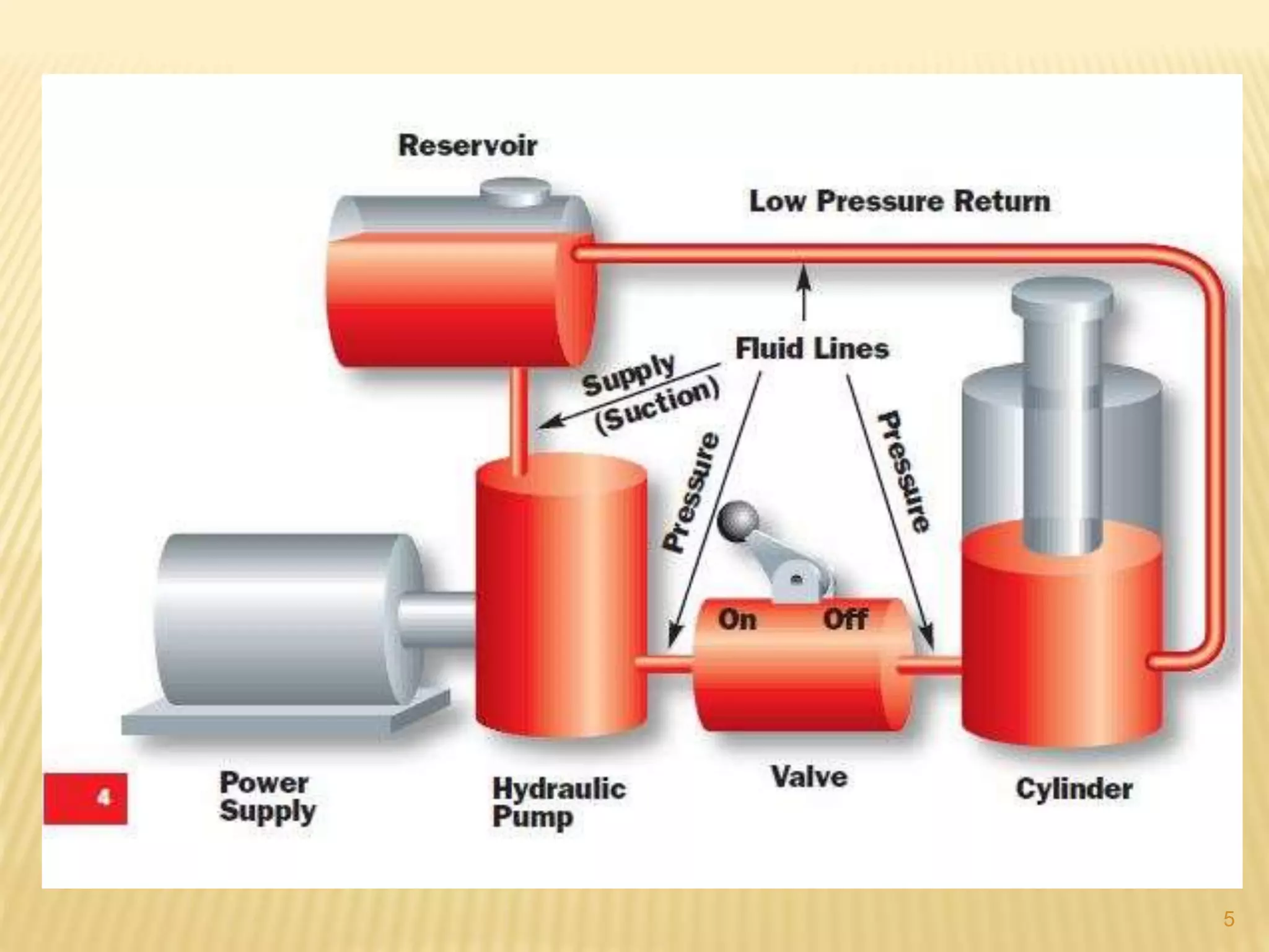


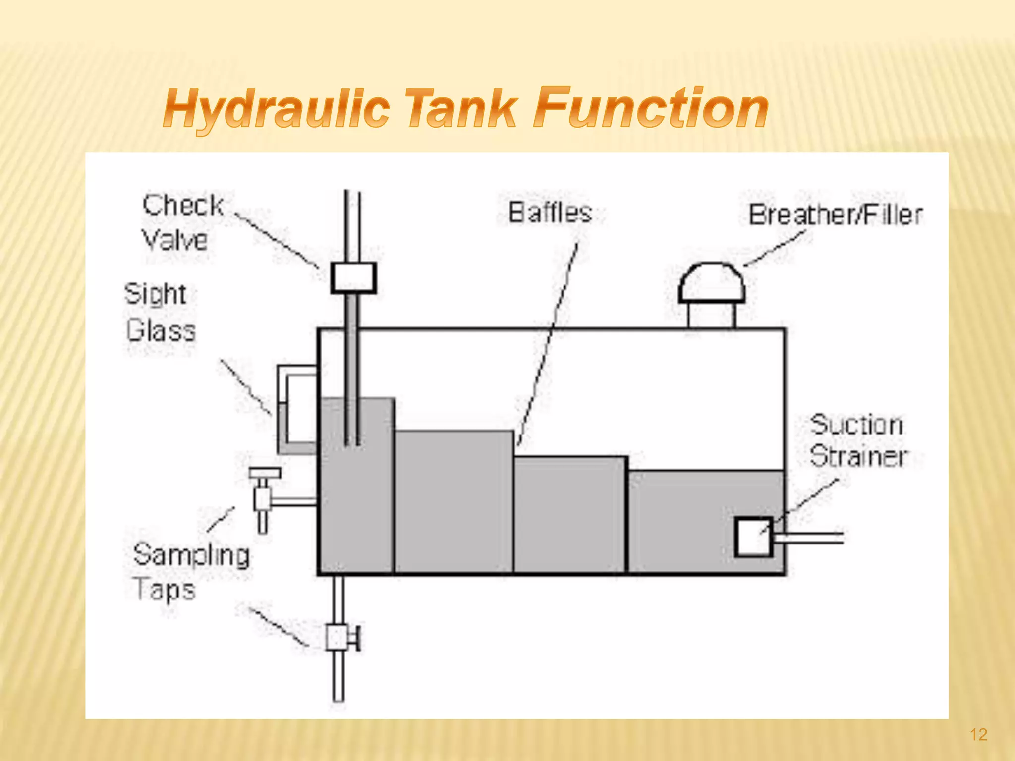
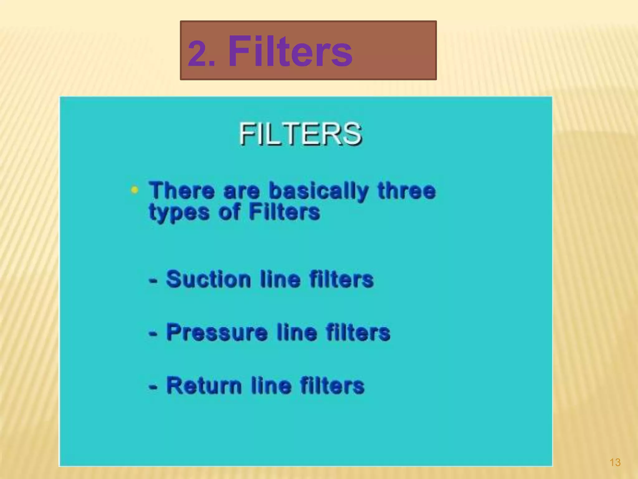

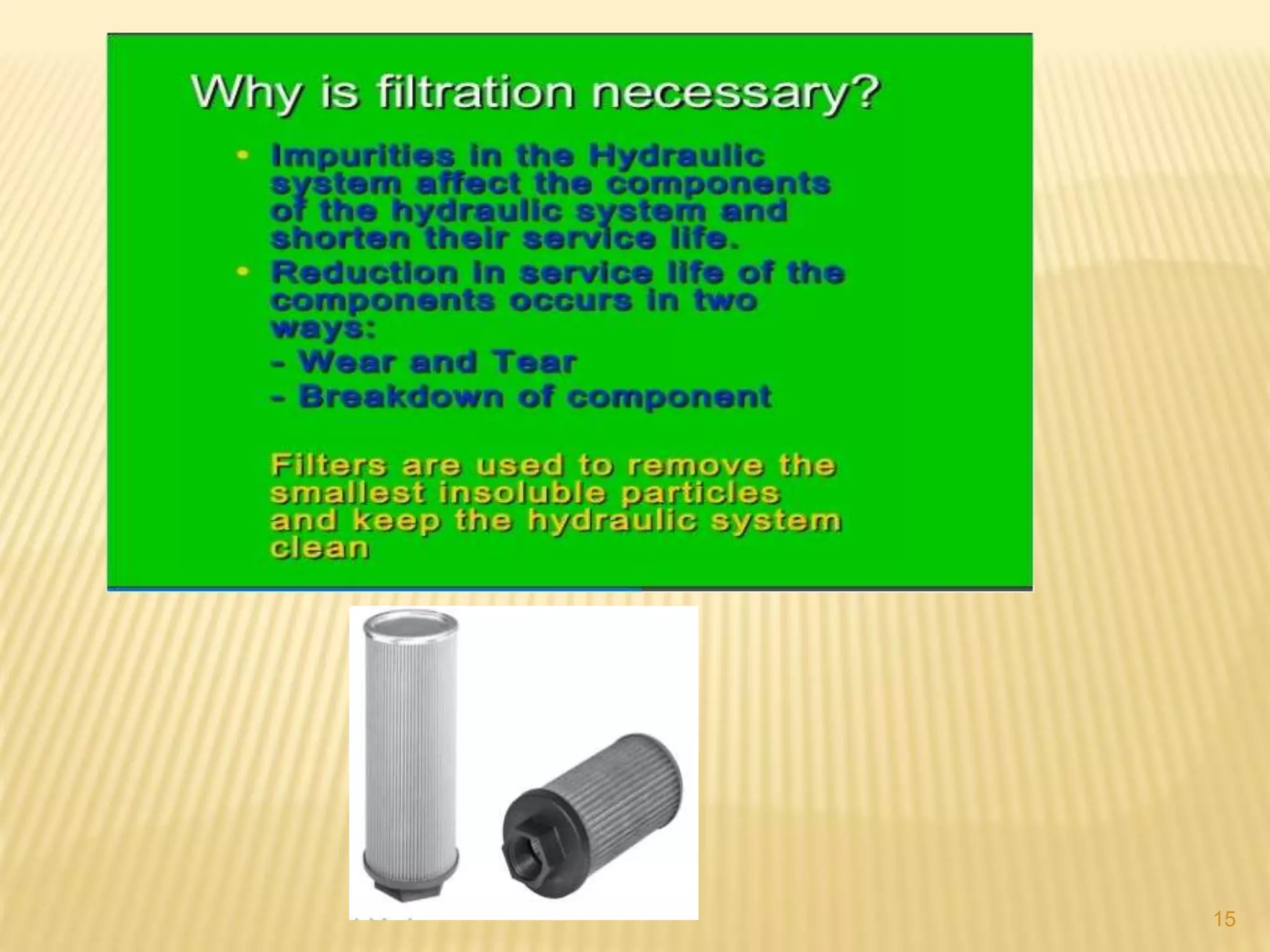


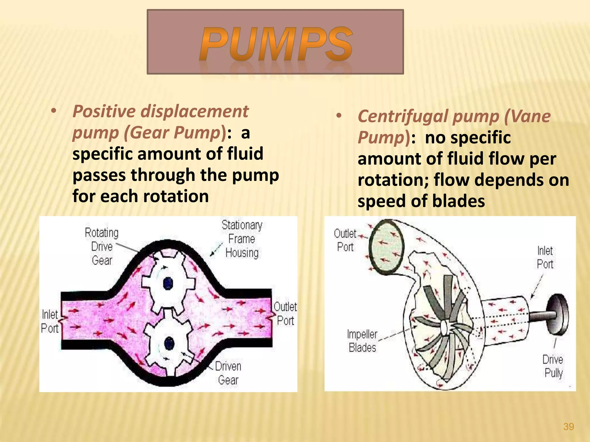


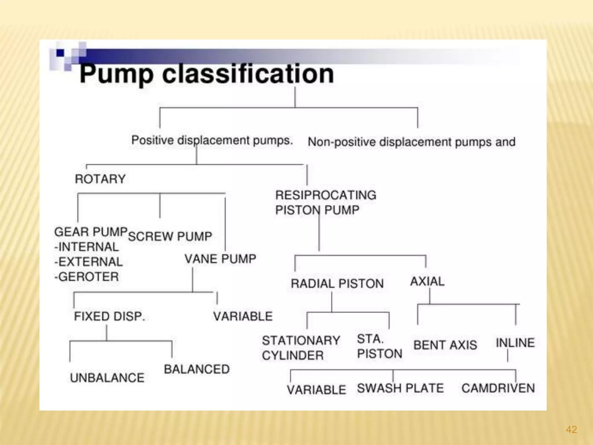


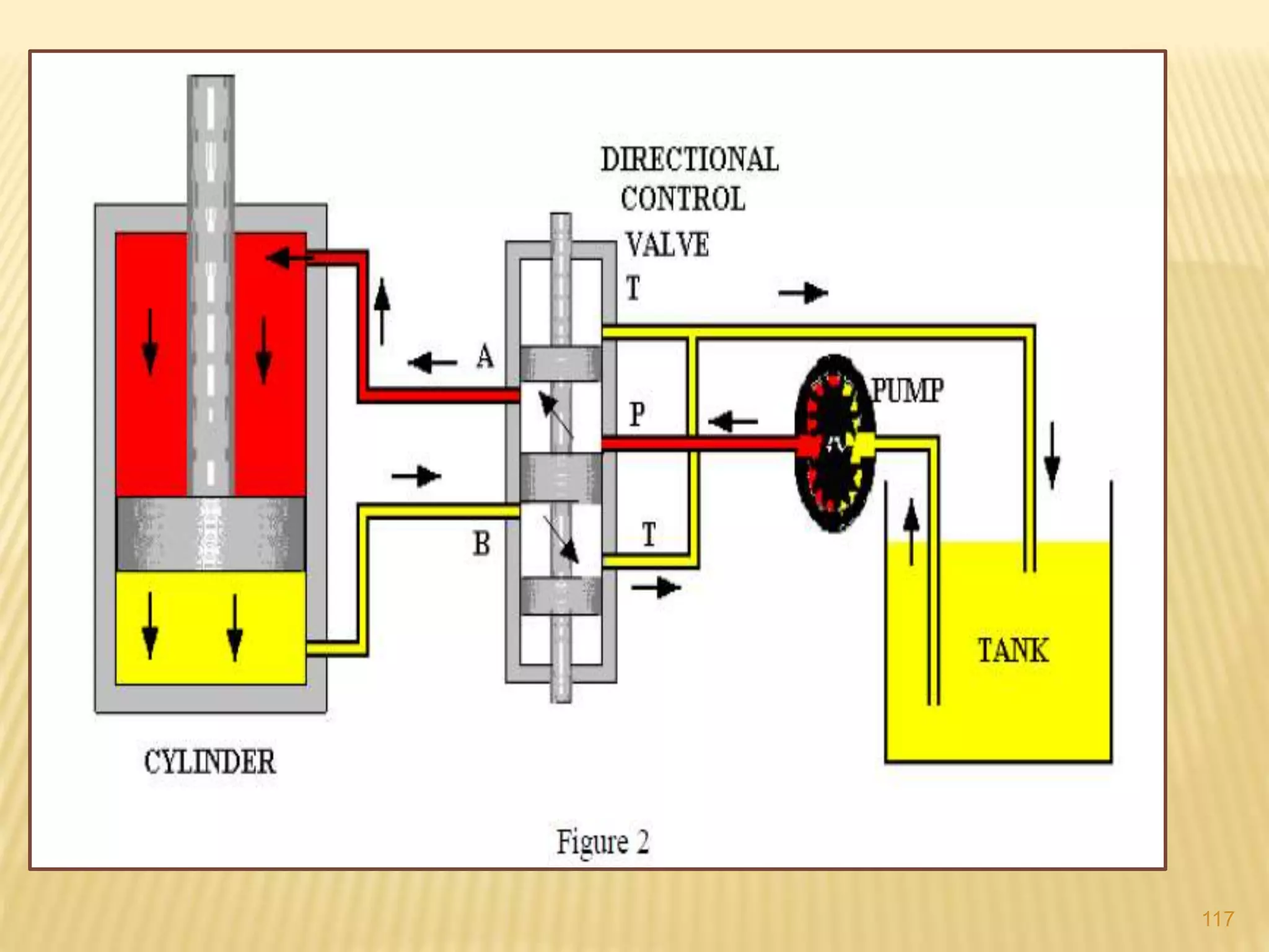


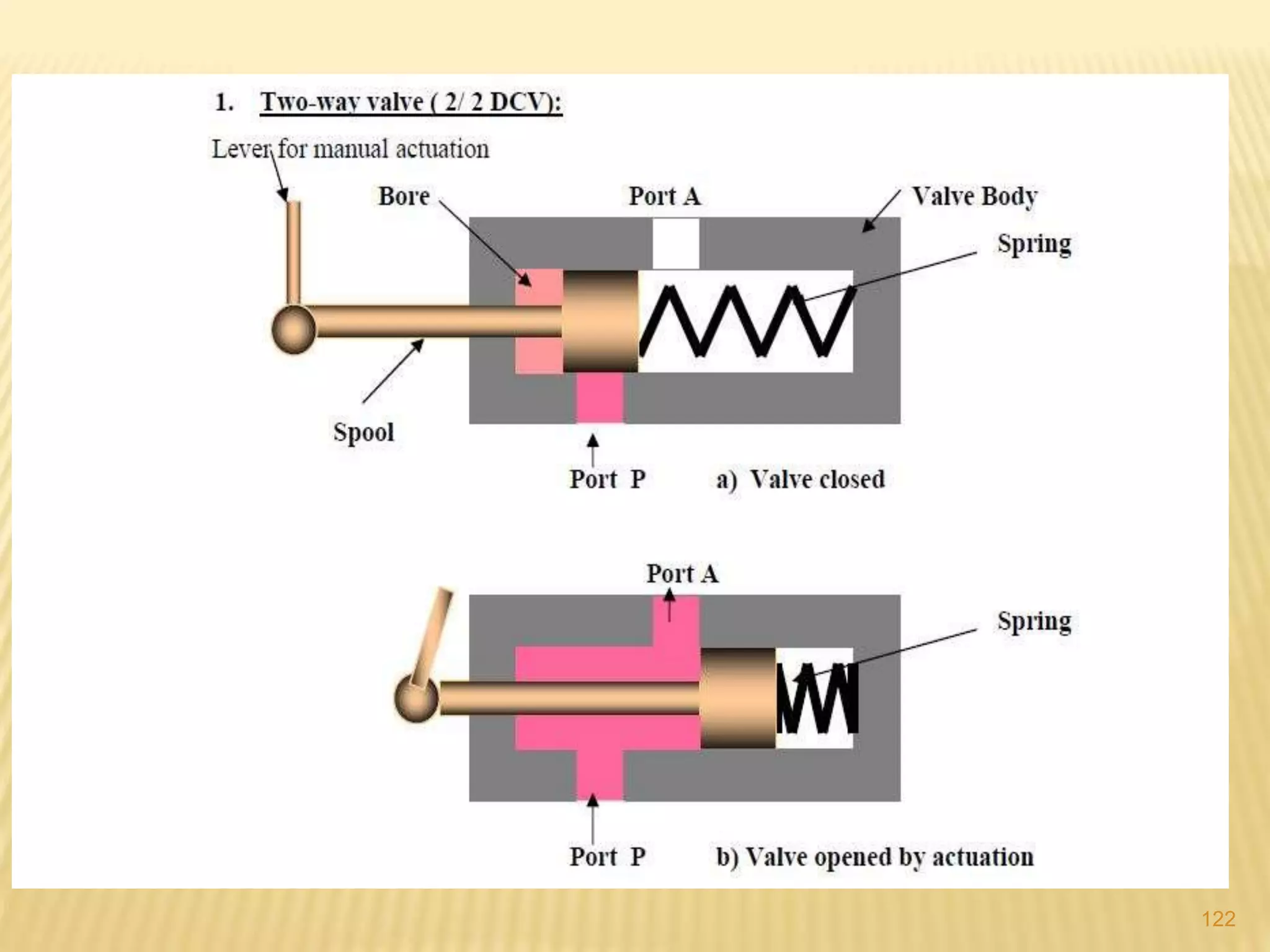
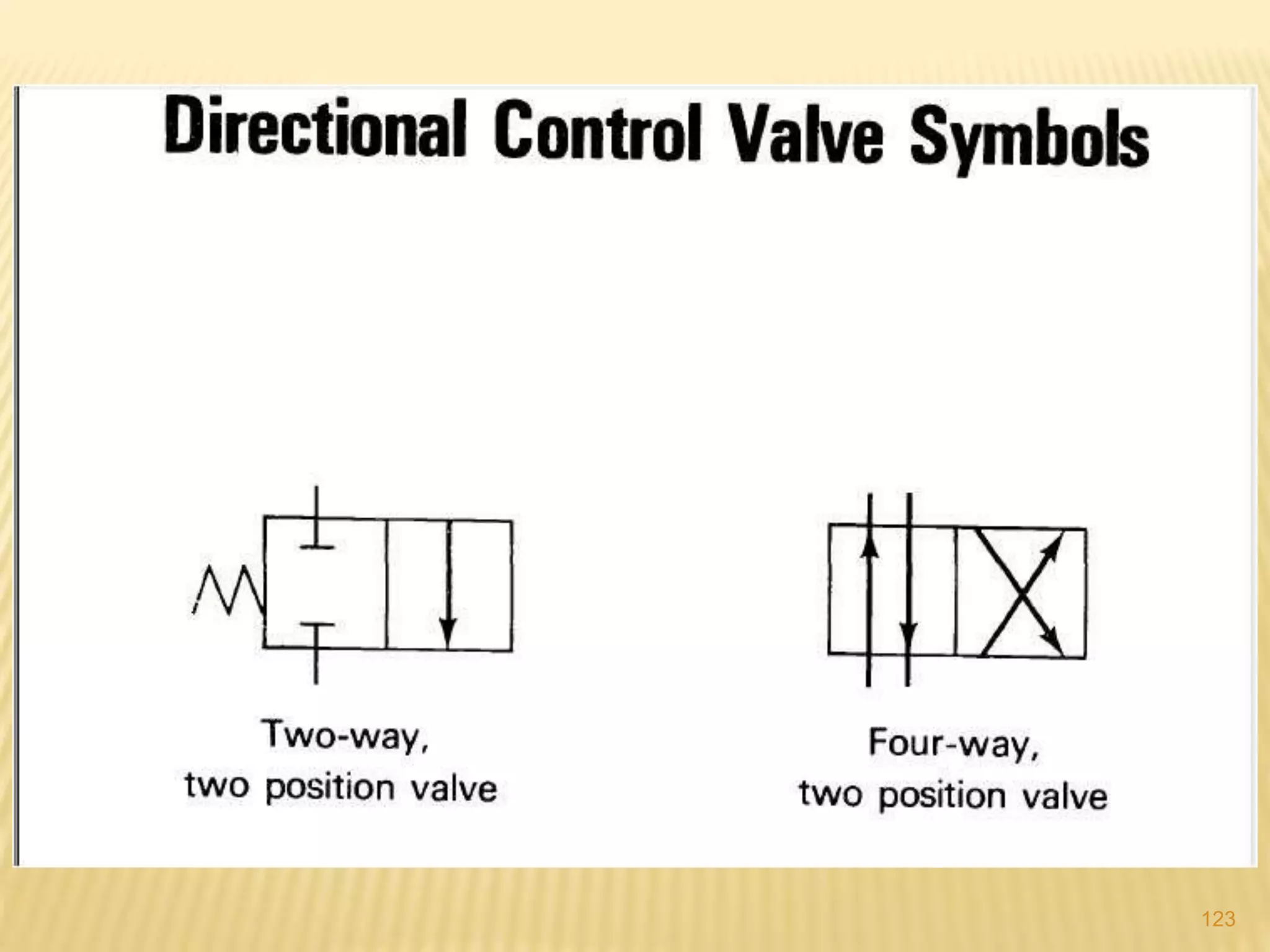


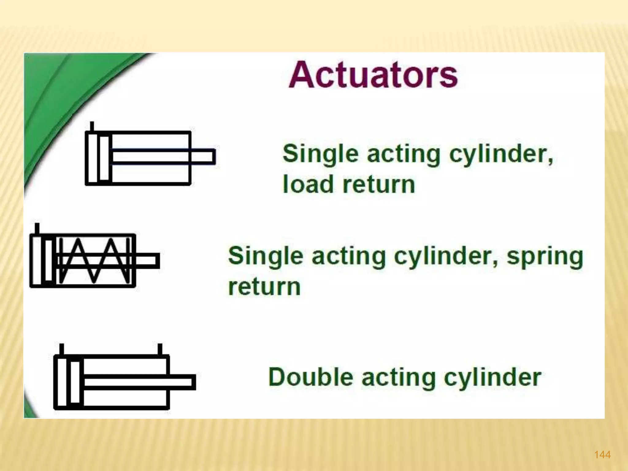
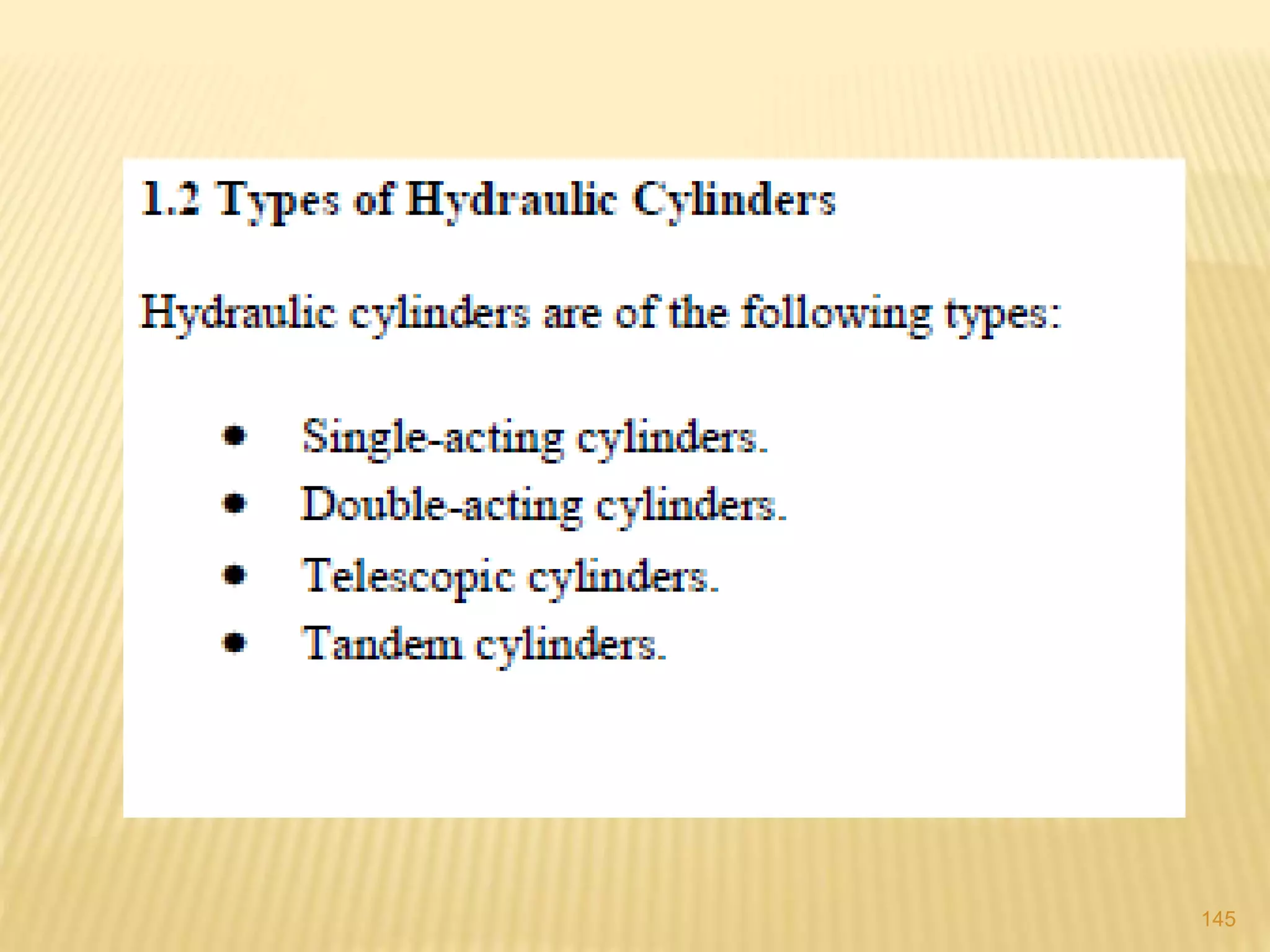
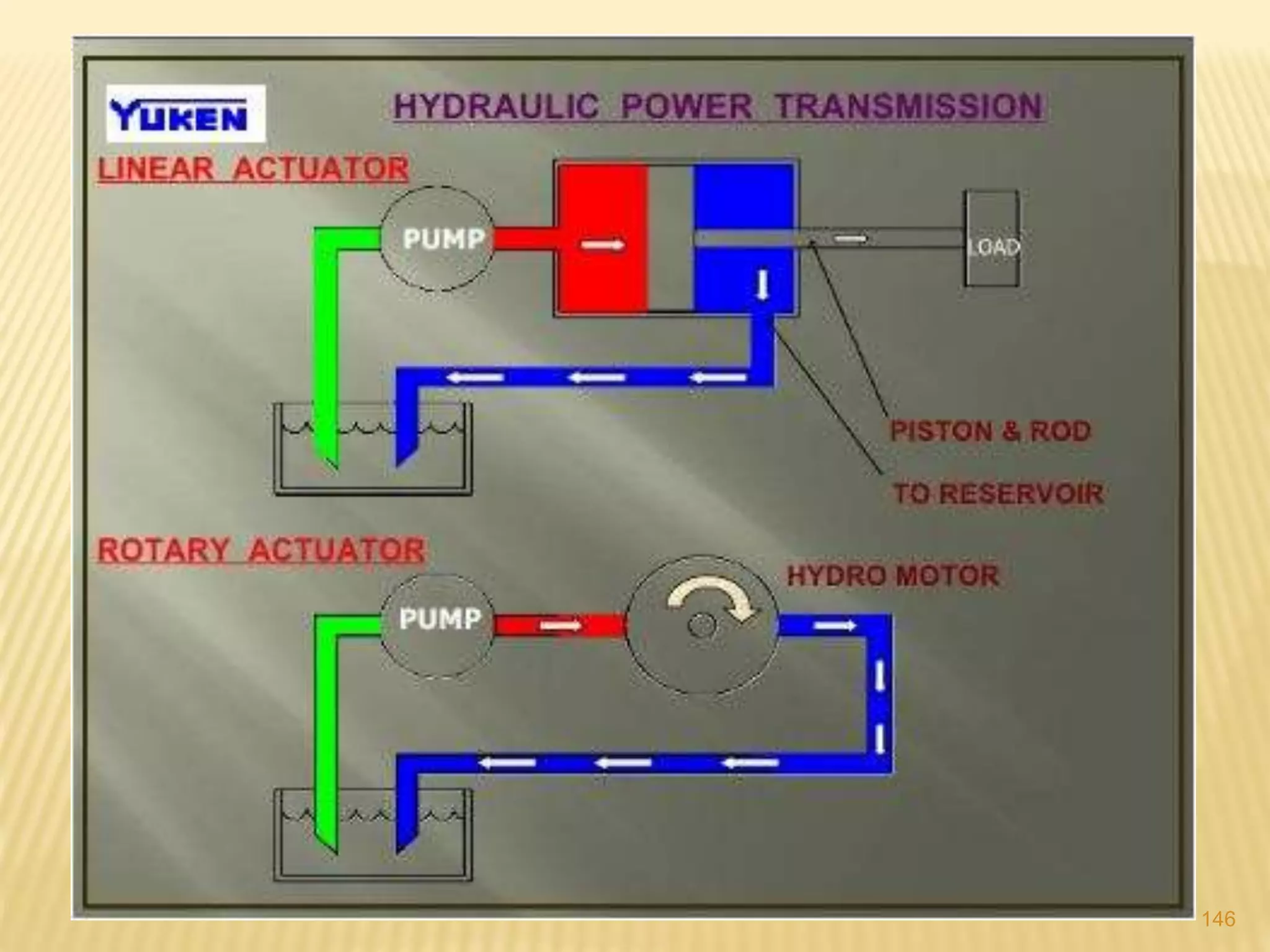
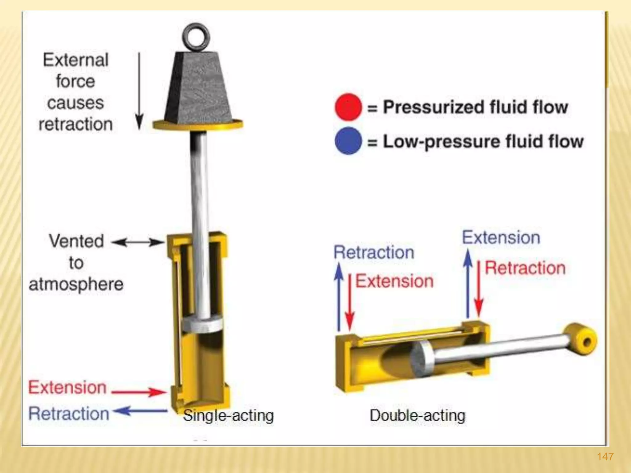


The document provides a comprehensive overview of hydraulic systems, detailing their primary components including power sources, control units, and drive units. It elaborates on various types of pumps, valves, and hoses used in hydraulic machinery, emphasizing the distinction between positive displacement and centrifugal pumps. Additionally, it discusses the functioning of actuators and the role of hydraulic motors in converting fluid power to mechanical work.


