Downloaded 1,592 times

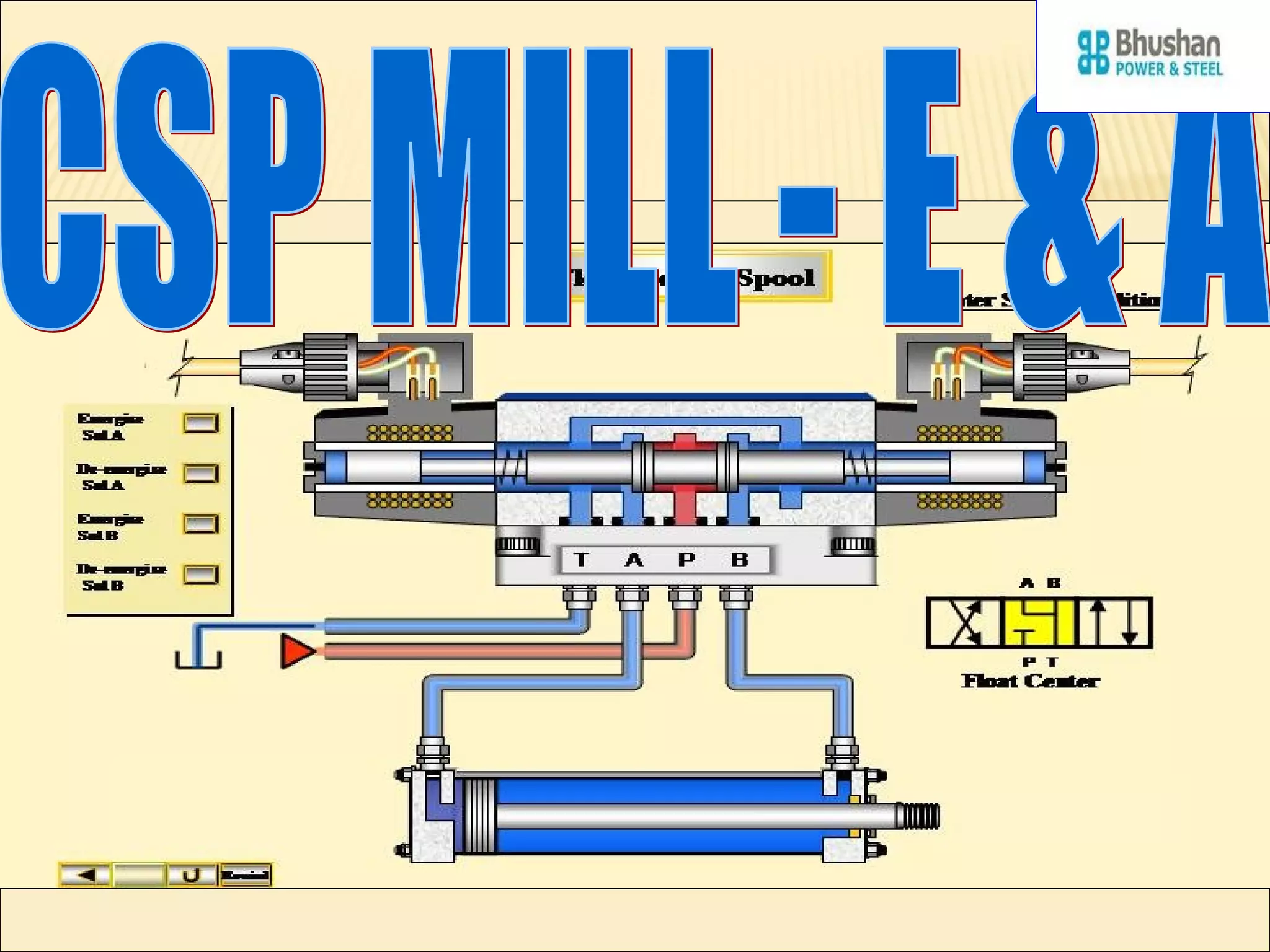
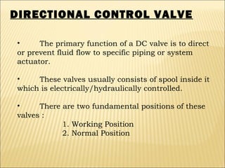
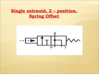
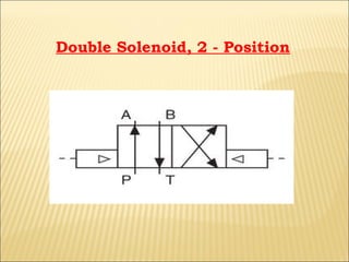
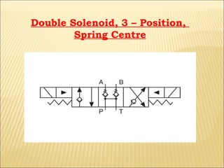
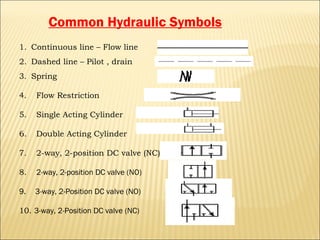
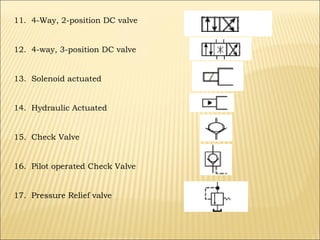
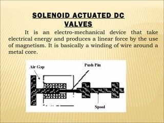
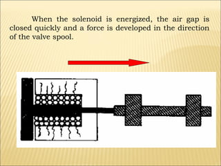
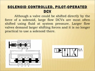
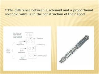


The document presents an overview of various types of directional control valves (DCVs) including solenoid actuated and pilot controlled check valves, detailing their functions, operations, and key components. It explains the differences between solenoid valves and proportional valves, emphasizing the role of current signals in their operation, as well as the importance of servo valves for precise control in hydraulic systems. Additionally, it covers the mechanics of these valves, providing insights into their construction, control mechanisms, and common applications in hydraulics.


