Downloaded 733 times
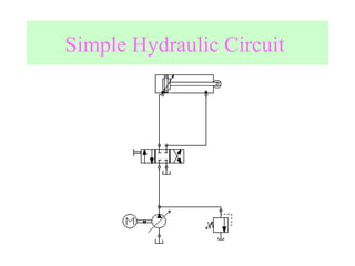
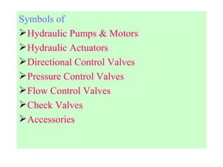
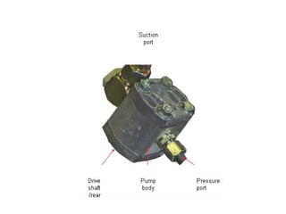
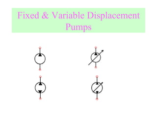
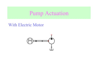
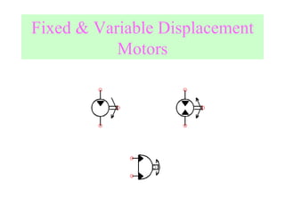
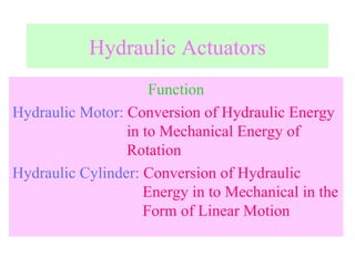
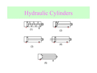
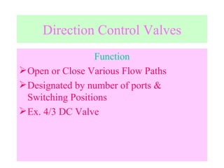
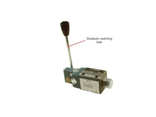
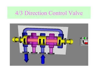
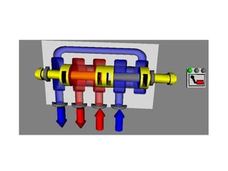
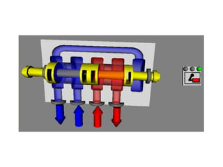
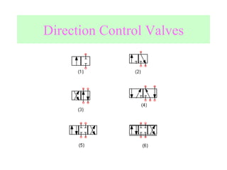
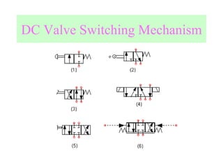
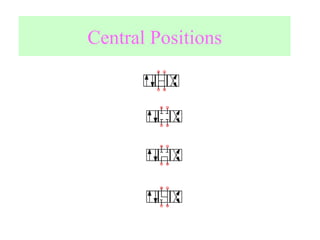
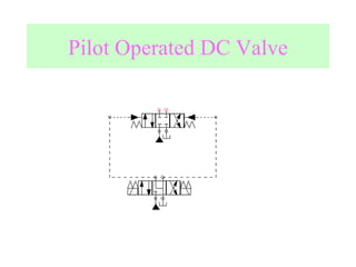
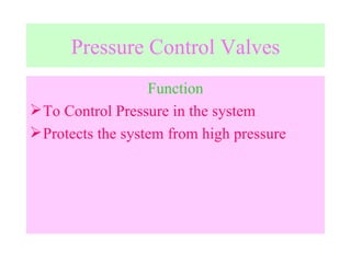
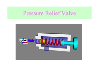
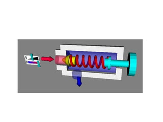
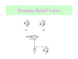

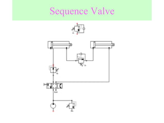
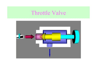
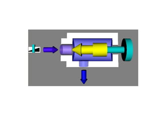
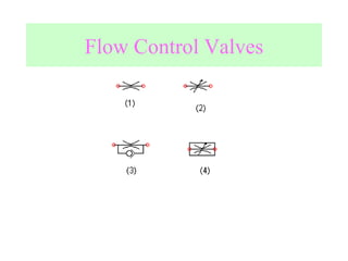
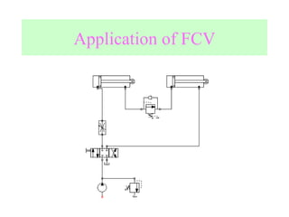
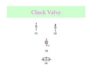
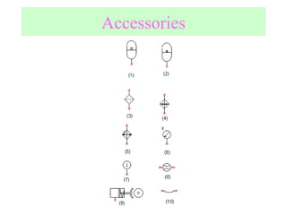

The document discusses hydraulic symbols according to ISO 1219 standards, including symbols for hydraulic pumps and motors, actuators like cylinders, directional control valves, pressure control valves, flow control valves, check valves, and other accessories. It provides information on the functions of different hydraulic components like pumps converting mechanical to hydraulic energy, motors converting hydraulic to mechanical rotation, cylinders providing linear motion, and various valve types controlling direction, pressure, and flow within hydraulic circuits.


