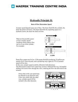
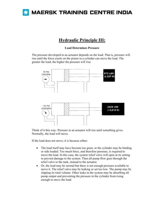
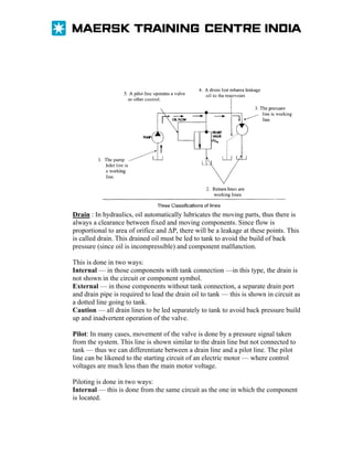
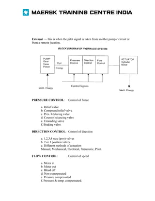
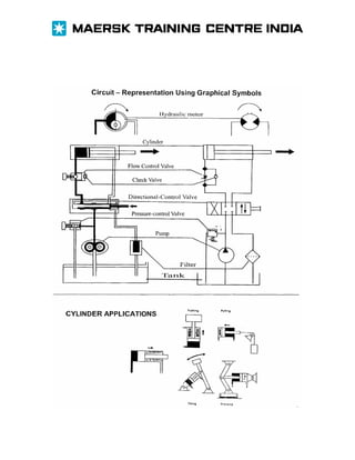
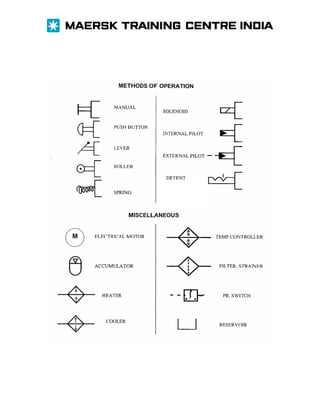
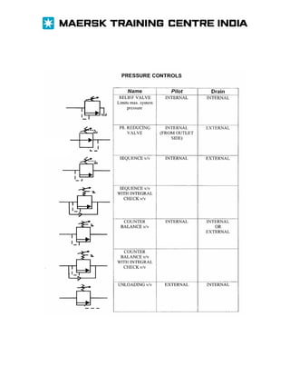
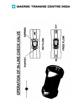
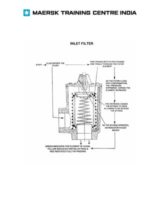
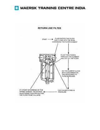
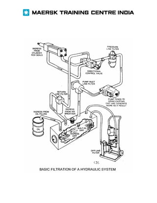
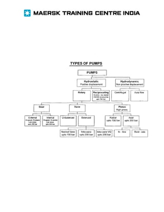
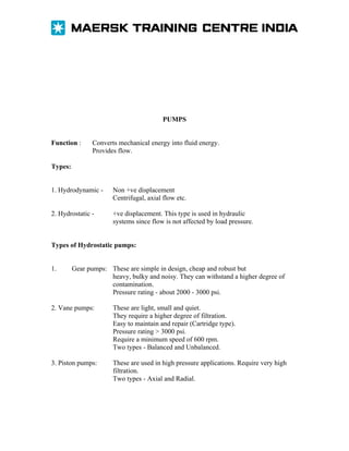
OBJECTIVE

1. TO UNDERSTAND FUNDAMENTAL PRINCIPLES OF HYDRAULICS
2. TO READ HYDRAULIC CIRCUIT DIAGRAMS WITH THE HELP OF
SYMBOLS
3. TO KNOW THE CONSTRUCTION & FUNCTION OF IMPORTANT
COMPONENTS USED IN HYDRAULICS
4. TO OPERATE, MAINTAIN AND TROUBLESHOOT HYDRAULIC
SYSTEMS IN ORDER TO CUT DOWN TIME AND NUMBER OF SERVICE
CALLS.
5. TO OPTIMISE SAFETY AND RELIABILITY
CONTENTS
Advantages of hydraulic systems
Fundamental principles
Block diagram of hydraulic systems
Component and circuit symbols
Hydraulic fluid
Reservoirs
Filters and contaminants
Pumps
Direction control valves
Solenoids for valve actuation
Pressure control valves
Flow control valves
Actuators
Accumulators
Cartridge valves
Proportional valves
Safety precautions
Maintenance and watch keeping
Hoses and hose fittings
Seals
Troubleshooting hints and guidelines
Thumb rules for hydraulic systems
Safematic operation for steering gear
ADVANTAGES:
1. AUTOMATIC LUBRICATION.
2. HIGH POWER I WEIGHT RATIO — small component can handle large
power.
3. SIMPLE DESIGN, FEW PARTS & LESS COMPLICATED
CONSTRUCTION.
4. FLEXIBILITY — same component can do different job
— can take power anywhere, only pipes, hoses required.
5. EASE OF CONTROL — only a lever required to start/stop/reverse the
actuator.
6. PRECISE MOTION CONTROL — jobs exactly as required, less waste &
better quality.
7. FORCE MULTIPLICATION ACHIEVED WITHOUT LEVERS, PULLEYS,
GEARS, AND CHAINS ETC.
8. BETTER SPEED CONTROL — from <1rpm to >1000 rpm (motor can even
be made to stall).
9. INSTANT STOPPING / REVERSIBILITY.
10. CONSTANT TORQUE WITH VARIABLE SPEED SINCE TORQUE ∞
PRESSURE AND SPEED ∞ FLOW
11. INBUILT SAFETY — actuator can be stalled at full load (even if relief valve
lifts — it will reset immediately when overload is removed.
12. AUTOMATIC BRAKING — by blocking flow, no brakes, linings etc.
required.
13. CAN BE USED IN HAZARDOUS CONDITIONS.
PASCALS LAW
Pressure applied to a confined fluid is transmitted undiminished in all
directions, and acts with equal force on equal areas, and at right
angles to them

A 10 lb force is
applIed to a stopper
with a surface area
of one squara inch.

results In 10 lb. of force on
every square Inch (pressure)
of the container wall.
The bottle Is filled
with a lIquid, which
Is not compressible.

If the bottom has an area of 20 sq.
in. and each square Inch is pushed
on by 10 lb. of force, the entIre
bottom receIves a 200 lb. push.
FUNDAMENTAL PRINCIPLES

1. PASCAL’S LAW: Pressure exerted on a confined fluid is transmitted
undiminished in all direction and acts with equal force on equal areas & at right
angles to them.
2. Hydraulics is a means of power transmission.
3. Work is force acting through a distance.
WORK = FORCE x DISTANCE. W = F x D = Energy used.
4. Power is the rate of doing work. POWER = WORK/TIME = F x D/T.
5. A pump does not pump pressure, its purpose is to create flow. Pumps used to
transmit power are usually positive displacement types.
6. Pressure is caused by resistance to flow. A pressure gauge indicates the work
load at any given moment.
7. Fluids take the path of least resistance.
8. A fluid is pushed, not drawn in-to a pump.
9. Pressure at the bottom of a one foot column of oil will be approximately 0.4
PSI. T o find the approximate pressure at the bottom of any column of oil,
multiply the height in feet by 0.4.
10. Atmospheric pressure equals 14.7 PSIA at sea level. Gauge readings do not
include atmospheric pressure unless marked PSIA.
11. There must be pressure drop (pressure difference) across an orifice or
restriction to cause flow through it. Conversely, if there is no flow there will be no
pressure diffrence.
12. Flow velocity through a pipe varies through a pipe varies inversely as the
square of the inside diameter. Reducing the diameter by half increases the velocity
by four times.
13. Friction losses (pressure drop) in a pipe are directly proportional to velocity.
14. One H.P. = 33,000 ft.lbs per minute or 33,000 lbs. Raised one foot in one
minute.
15. 1 H.P. = 746 WATTS = 42.4 BTU/MIN.
16. KW = L.P.M. x BAR/600.
17. H.P. = G.P.M. x PSI xO.000583.
18. H.P. of a prime mover = GPM x PSI x 0.0007.
Hydraulic Principle I:
Movement depends on Flow
For anything to move in a hydraulic machine, the actuators must be supplied with
fluid flow. Nothing moves without flow.

This cylinder is retracted. It can extend only if there is flow into port A. If there is
no flow into port A, the piston will not move.
Hydraulic Principle II:
Rate of Flow Determines Speed
Actuator speed depends upon rate of flow. The faster fluid fills the cylinder, the
faster the piston will move. The faster fluid fills the expanding spaces in a
hydraulic motor, the faster the shaft will turn.

What are the possible causes
of slow actuator speed?
Anything which reduces flow
rate in or out of the cylinder.
For example:

Pump flow output may be low. If the pump should be producing 10 gallons per
minute (0.631 liters/second), and is producing only 6 gpm (0.379 l/s) actuator
speed will be slow.
In this case, actuator speed would be affected in both directions.
The Directional Control Valve spool may not have shifted all the way. Incomplete
shifting will restrict flow through the valve, reducing the flow rate delivered to the
actuator.
Notice that in this case speed may
be affected in one direction only.
If the valve shifts fully the other
way, cylinder speed will be
normal in the other direction.
Hydraulic Principle III:
Load Determines Pressure
The pressure developed in an actuator depends on the load. That is, pressure will
rise until the force exerts on the piston in a cylinder can move the load. The
greater the load, the higher the pressure will rise.

Think of it this way: Pressure in an actuator will rise until something gives.
Normally, the load will move.
If the load does not move, it is because either:
•

•

The load itself may have become too great, or the cylinder may be binding
or side loaded. Too much force, and therefore pressure, is required to
move the load. In this case, the system relief valve will open at its setting
to prevent damage to the system. Then all pump flow goes through the
relief valve to the tank, instead to the actuator.
Or, the load may be normal but there is not enough pressure available to
move it. The relief valve may be leaking or set too low. The pump may be
slipping its total volume. Other leaks in the system may be absorbing all
pump output and preventing the pressure in the cylinder from rising
enough to move the load.
1. The oil can choose three paths.
2. It first chooses Valve A because
only 100 psi is required. A pressure
gauge at the pump will read 100 psi.

A. FLOW IS THROUGH 100 psi VALVE

B. FLOW IS THROUGH 200 psi VALVE
SERIES RESISTANCES ADD PRESSURE
Drain : In hydraulics, oil automatically lubricates the moving parts, thus there is
always a clearance between fixed and moving components. Since flow is
proportional to area of orifice and ΔP, there will be a leakage at these points. This
is called drain. This drained oil must be led to tank to avoid the build of back
pressure (since oil is incompressible) and component malfunction.
This is done in two ways:
Internal — in those components with tank connection —in this type, the drain is
not shown in the circuit or component symbol.
External — in those components without tank connection, a separate drain port
and drain pipe is required to lead the drain oil to tank — this is shown in circuit as
a dotted line going to tank.
Caution — all drain lines to be led separately to tank to avoid back pressure build
up and inadvertent operation of the valve.
Pilot: In many cases, movement of the valve is done by a pressure signal taken
from the system. This line is shown similar to the drain line but not connected to
tank — thus we can differentiate between a drain line and a pilot line. The pilot
line can be likened to the starting circuit of an electric motor — where control
voltages are much less than the main motor voltage.
Piloting is done in two ways:
Internal — this is done from the same circuit as the one in which the component
is located.
External — this is when the pilot signal is taken from another pumps’ circuit or
from a remote location.

PRESSURE CONTROL:

Control of Force

a. Relief valve
b. Compound relief valve
c. Pres. Reducing valve
d. Counter balancing valve
e. Unloading valve
f. Braking valve
DIRECTION CONTROL: Control of direction
a. 1,2,3,4 way (port) valves
b. 2 or 3 position valves
c. Different methods of actuation
Manual, Mechanical, Electrical, Pneumatic, Pilot.
FLOW CONTROL:

Control of speed

a. Meter in
b. Meter out
c. Bleed off
d. Non-compensated
e. Pressure compensated
f. Pressure & temp. compensated.
FUNCTIONS AND PROPERTIES OF HYDRAULIC OIL

FUNCTIONS:
1. TRANSMITS POWER
2. LUBRICATES COMPONENTS
3. REMOVES AND AIDS IN DISSIPATING HEAT FROM THE SYSTEM
4. TENDS TO SEAL CLEARANCES
5. INHIBITS RUST! CORROSION
6. ACTS AS A BRAKE WHEN REQUIRED

PROPERTIES:
1. VISCOSITY (similar to electrical resistance) 2. LUBRICITY
3. FILM STRENGTH
4. POUR POINT
5. FLASH POINT
6. DEMULSIBILITY (ability to separate from water rapidly)
7. RESISTANCE TO FOAMING (ability to quickly give up air)
8. CHEMICAL STABILITY - resistance to oxidation
9. ANTI WEAR PROPERTIES
10. COMPRESSIBILITY
Additives are added to the oil to improve the above properties and thus extend
the life of the oil.
EFFECT OF VISCOSITY ON HYDRAULIC SYSTEMS:

IF THE VISCOSITY IS TOO HIGH:
1. The internal friction of the fluid will increase resulting in increase in the flow
resistance.
2. The machine and fluid temperature will increase.
3. Machine operation will be sluggish.
4. Pressure drop throughout the system will increase.

IF THE VISCOSITY IS TOO LOW:
1. Internal and external leakage will increase.
2. Pump slippage will increase and reduce pump efficiency and increase oil temperature.
3. Increase in friction between the moving parts will result in increased wear and more
heat evolution.
4. The system will operate at a lower pressure.
5. There will be a loss of precise control.
IMPORTANCE OF RESERVOIRS
RESERVOIR:
Functions:
1. To aid in expelling entrained air.
2. Cooling the hydraulic fluid.
3. Aids in removing contaminants.
Important design aspects:
1. Tank capacity should be about 3 — 4 times the gpm of the pump.
2. It should be on legs, not flush with deck — to aid heat transfer & to enable complete
draining.
3. Baffle plate to be placed between return lines and pump suction line.
4. Breather cap to be fitted & kept tightly in place.
5. Sight glass / level gauge to be kept clean and operational.
6. Return line bottom edge to be chamfered.
7. Level of oil in tank to be maintained at least 3 — 4” above the suction filter.
FILTERS AND CONTAMINANTS
Filter types:
1. Suction line filter — about 100 — 200 microns.
2. Pressure line filter — about 5 — 10 microns.
3. Return line filter — about 20 — 40 microns.
4. Off line filtration.
5. Full flow filters.
6. Proportional flow filters.
7. Filters with 3 P indicators and / or inbuilt bypass valves.
Importance of regular checks and cleaning / renewal of line filters cannot be overstressed.
While replacing filter elements, it should be ensured that the new element is of correct
type and size.
SOURCES OF CONTAMINANTS
1. Builtin dirt.
2. Present in initial charge of oil.
3. Ingress while filling new oil — to use 10 micron filter.
4. Ingress through loose breather cap — keep tight — check filter element.
5. Generated in cylinder.
6. Ingress from cylinder oil seals.
7. Generated in pump, valves etc.
8. Ingress of rust, paint flakes from tank.
9. Introduced during repairs.
Maximum abrasion occurs due to particles slightly smaller or the same size as the
clearance between moving parts.
Hydraulic Fluid Cleanliness Requirements
Cleanliness requirements for hydraulic fluids have changed significantly in recent years.
The standard of cleanliness that was acceptable a few years ago is no longer sufficient for
many of today’s hydraulic systems. This is especially true for highly-automated facilities,
such as electrohydraulic servo valves, numerically controlled machines, and aircraft and
missiles system. A hydraulic system may be perfect with respect to the design and
construction, but if the fluid that is used in the system contains excessive contamination,
either the operation of the equipment may be unsatisfactory or damage to the unit may
occur.
A number of different classification system have been used by various organization and
individual companies to define and measure the cleanliness level for the hydraulic and
lubricating fluids that are used in equipment. To standardize the method used to express
the level of particulate contamination in hydraulic fluid, the International Standards
Organization (ISO) developed standard 1S04406. ISO 4406 is an internationally
recognized standard that not only expresses the level of particulate contamination of a
hydraulic fluid, but it is also used to specify the required cleanliness for hydraulic
components and system. This widely accepted system provides a consistent and
meaningful standard that can be used by all manufacturers and users.
KEEPING HYDRAULIC FLUIDS CLEAN
Cleanliness of the hydraulic fluid and system is essential to maintaining the longest
possible service life of the fluid and to ensuring trouble-free operation of the system.
System cleanliness starts with keeping the hydraulic fluid clean and free of contamination
during the storage and installation.
STORAGE AND HANDLING
Hydraulic fluid suppliers are careful to ensure that the fluid is clean when it is delivered
to the customer. The customer must follow storage and handling precautions to ensure
that the fluid is clean when it is installed in the system. These storage and handling
precautions are recommended to prevent contamination of the fluid by materials such as
dust, water and dirt. The following are some of the precautions for storage and handling
that are recommended by hydraulic fluid suppliers.
Drums of hydraulic fluid should be stored on their sides to prevent any accumulation of
moisture, dirt and dust on the top of the drum.
Drums should be stored indoor or under some sort of shelter to keep the drums out of the
harsh effects of the elements.
The top of the drum must be cleaned of dirt or moisture before opening to prevent dirt or
moisture from falling into the drum and contaminating the fluid.
Hydraulic oils received in bulk should be filtered into clean tanks or other storage vessels.
Equipment that is used to transfer the fluid from the storage containers to the reservoirs
(hoses, pumps, etc) should be equipment that is specifically designated for that purpose.
The general use of any hose or container will cross contaminate the hydraulic fluid. The
transfer equipment must be thoroughly cleaned prior to use. Hoses should have their ends
capped, and containers should be covered after use to prevent the entrance of
contaminants.
Because many facilities use different types of hydraulic fluids in different system,
equipment that is used to transfer fluid to these systems should be designated and used for
each different fluid to prevent cross-contaminating noncompatible fluids.
Even though fluid suppliers are careful to deliver only clean fluid, a filtration system
should be used to transfer the fluid to the reservoir. The degree of filtration should be the
same as the filtration system that is used on the equipment. Many fluid suppliers will
provide hydraulic fluid filtration system specifically designed for filtering fluid as it is
added to the system. Facilities should establish and follow hydraulic fluid standards and
practices to prevent the contamination of hydraulic system from the improper storage and
handling of hydraulic fluids.
Example:
Sample size = 100 ml
Particle size range
5— 15 μm
15—25 μm
25—50 μm
50—100 μm
>100 μm

Number of particles
50
150,000
5,000
1,250
250

Thus, total number of particles. ‘
>5μm=156,55O
>15 μm =6,550
These two values are plotted on the
graph as shown, which gives the
code as’ 18 /13’
3.1 Classification systems for the degree of
contamination in a fluid
Classification systems (standardised
cleanliness classes) are used to help
determine the amount of sijlld particles
present in a fluid.
The most commonly used standards today
are NAS 1638 and ISO DIS 4406.
3.11 Classification to NAS 1638
Fourteen cleanliness classes exist to
classify fluids. In each class a specific
number of particles (in 100 ml) is given for
each of 5 ranges of sizes.
Table 6 shows how contamination classes
are formed to
NAS 1638.

3.1.2 Claasltlcallon to ISO DIS 4406
Here the sizes larger than 5 im and larger
than 15 im are cumulatively provided.
The cleanliness class of the fluid is
determined on the basis of both particle
counts.
Twenty-six ranges are available for
classification. The designation of the
cleanliness class comprises only two
numbers. The first number indicates the
range number for the particle size larger
than 5 tm and the second number indicates
that for the particle size larger than 15 urn,
Diagram 1 illustrates the contamination
class to ISO DIS
4406.
DEAR CUSTOMER!
In this Service Bulletin we will highlight the hydraulic oil and the filtration.
As we all know the cleanliness of the oil as well as the as the general oil condition is very
important for the lifetime of the system.
The practical life has shown that some of the ‘FRAMO ships’ are sailing around with far
too high particle level in the hydr. oil.
Our recommended level of particles in the system is:
ISO 4406 code 16/12.
This means:
Number of particles per ml ≥ 5 µm: 320, max 640
Number of particles per ml ≥ 15µm: 20, max 40
With FRAMO original filter element this cleanliness level should not be of any problem
to maintain.
Nevertheless, we have found ships sailing around with more than 2-3 thousand particles
per ml between 5 -15µm.
This is very costly in the end, and we therefore strongly advise you to pay attention to the
filtration and the cleanliness of the hydr. oil.
As you know the hydr. oil has four main functions in the system:
1: Transmit the power from the aggregates to the different consumers.
2: Lubrication of all moving parts.
3: Transfer all produced heat back to the cooler.
4: Transfer all dirt back to the filter.
Do not play around with non FRAMO oil filter elements.
Be aware of the following important filter specifications:
1) The filter Beta Ration (β)
Normal FRAMO filters have a Beta Ration = β 12 ≥75.
This means if 75 particles of 12 pm or bigger come into the filter only one passes
through. In other words the Beta Ration is the filter’s ability to stop the particles, i.e.
β = particles in ÷ particles out
2) The filter dirt capacity
Filter with higher dirt capacity gives longer service intervals and improved economy..
Particles counting combined with pressure drop over the filter is the only safe indicator
when to change the filter element.
FRAMO offices in Bergen, Rotterdam, Houston and Singapore can offer hydr. oil
monitoring and particle counting.
It is essential that the oil sampling is provided regularly, from the same highlighted
sampling point, and in an absolutely clean sampling bottle.
Q: What should be the Hydraulic Oil Cleanliness Standard for our type of Hydraulic
System? And what should be the micron ratings of the Filter for such systems?
A: Following are the recommended Oil Cleanliness Levels for different Hydraulic
Systems and absolute micron ratings of the filters used in the system. However as a
thumb rule Oil Cleanliness Level required for the most sensitive component of the system
should be maintained. Recommended Oil Cleanliness levels for different Components are
as per next table.
PUMPS
Function :

Converts mechanical energy into fluid energy.
Provides flow.

Types:
1. Hydrodynamic -

Non +ve displacement
Centrifugal, axial flow etc.

2. Hydrostatic -

+ve displacement. This type is used in hydraulic
systems since flow is not affected by load pressure.

Types of Hydrostatic pumps:
1.

Gear pumps: These are simple in design, cheap and robust but
heavy, bulky and noisy. They can withstand a higher degree of
contamination.
Pressure rating - about 2000 - 3000 psi.

2. Vane pumps:

These are light, small and quiet.
They require a higher degree of filtration.
Easy to maintain and repair (Cartridge type).
Pressure rating > 3000 psi.
Require a minimum speed of 600 rpm.
Two types - Balanced and Unbalanced.

3. Piston pumps:

These are used in high pressure applications. Require very high
filtration.
Two types - Axial and Radial.
COMMON PROBLEMS WITH PUMPS:
1. Contamination -

This will result in loss of lubrication & increase in clearances.

2. Cavitation -

This is caused when pressure at pump suction
becomes 5”Hg (about 2.5 psi) below atmospheric.
Tank oil level low.
Suction filter clogged.
Oil viscosity higher than design - due wrong oil or low temp.
Long length and / or bends in suction line.
Inlet pipe clogged.
Breather cap choked.
Pump running higher than rated speed.

Causes -

3. Aeration Causes -

This is caused by presence of air in the system.
Can occur only from suction side of the pump.
Leaking suction line fittings.
Pump shaft seal leaking.
Return / drain lines not immersed in oil in tank.
High velocity of return oil.

Both cavitation and aeration will cause the pump to run with more noise than normal.
Diagram showing the relationship of even numbered positions verses the larger
diameter odd numbered position to relate how capacity is affected as rotation
occurs relative to the valve plate of an axial position pump.
A condition unique to the variable displacement pump is that seven, nine or eleven pistons are used
(Fig. 3.14). To explain why this significant, consider an axial piston pump that is designed with eight
pistons. At some point during the revolution of the cylinder barrel, two of the active pistons are located
directly over the lands used to segregate the two semicircular grooves. As the pistons are at the extremes of
their strokes, as well as not being aligned with either groove, the oil in the cylinders is unable to pass from
the cylinder barrel. Therefore, only six of the eight cylinders are at this instance.
As the cylinder barrel rotates a few degrees, the pistons that were positioned over the lands become aligned
with their respective semicircular grooves. At the same time, the pistons that pass over the lands next have
not as yet passed from the semicircular grooves. This means that all eight pistons are active at this instance.
With the constant change from eight to six and back to eight active pistons, pulsation’s are developed by
the pump. By reducing the number of pistons to seven, only one piston is always exposed to the lands.
When the number of pistons is reduced to seven, for example, the piston diameter is increased by one- tenth
of an inch. This also means that the capacity of the pump is increased. For comparison, the pump stroke is
held at a maximum of 1.25 inches.
Initially, the eight one-inch pistons are found to produce a displacement of 7.85 cubic inches per revolution.
Since it has already been stipulated that an average of two pistons cease to discharge during one revolution,
the effective discharge is six cubic inches per revolution.
Likewise, the pump with seven 1.1 inch- diameter pistons has a theoretical displacement of the remaining
six pistons is 7.4 cubic inches per revolution. Therefore, the capacity of the pump is improved by using an
odd number of pistons.
As previously stated, regardless of the length of the pump stroke, lubrication of all internal parts is possible.
First, you should realize that to have proper lubrication of all internal parts is possible. First, you should
realize that to have proper lubrication, continuous flow of the lubricant must exsist. The construction of the
radial piston pump floating ring, at neutral stroke, prevents the continuous flow of oil, because of the design
of floating ring. On the other hand, the axial piston pump produces an entierl different lubricating
condition.
DIRECTION CONTROL VALVES
These valves start, stop and control the direction (path) of fluid flow. They are classified
according to their principal characteristics as given below:
1. Type of internal valving element:
a. Poppet (ball or piston)
b. Rotary spool
c. Sliding spool (this is the most commonly found type)
2. Method of actuation:
a. Manual
b. Mechanical
c. Pneumatic
d. Hydraulic
e. Electric
f. Piloted
3. Number of flow paths:
a. One way (check valve)
b. Two way
c. Three way
d. Four way
4. Number of positions:
a. Two position
b. Three position
Two types of basic direction control valves:
THREE – POSITION 4 - WAY VALVES
Three position valves, with center neutral, are used in circuits where the cylinder must be
stopped in mid travel. The 3 — position valve pictured below has all ports blocked in
center neutral, but several other choices of center porting are commonly used, and these
are illustrated in diagrams on the following pages. The two side positions give the same
cylinder reversing action as the two — position valve previously described. The center
position is considered the “normal” position, and in drawing diagrams, all external circuit
connections should be made to the center block.
Pilot Operated Check Valves
These valves act like conventional non-return valves (i.e. aloe flow in one direction only),
but can be opened by pilot pressure to allow flow in the reverse direction Being poppet
type they are virtually leak-free when closed and are thus useful in preventing creep or
inadvertent movement of an actuator. They may also be used to prevent movement of an
actuator if a hose fails.
•
•
•

Flow into port A lifts poppet 1 off its seat, passes freely through and out of port B.
Flow into port B will act on top of the poppet which with spring 2 it closes onto
its seat preventing reverse flow B to A.
For reverse flow B to A pressure can be applied to pilot port X. This will push up
pilot piston 3 lifting poppet 1 off its seat.
1. General description
These modules provide pilot operated check functions in one or both service lines (A and
B), the pilot supply coming from opposite service line to that in which the check acts.
When closed, the check prevents flow from the actuator port to which it is externally
connected. The construction of a dual check module is shown below:

2. Functional Symbols
SOLENOIDS FOR DIRECTION CONTROL VALVE
ACTUATION.
These are the most common actuators for direction control valves.
The ones used in this application are of the ‘on - off type.
The solenoids always actuate the spool by PUSHING on it.
They can be DC (generally round shape & black) or AC (generally flat
sided and blue)
Solenoids are made up of two main parts - the coil (which receives the supply) and the
armature (which is the moving element).
Two solenoid designs in use are:
Air gap type - here an air space separates the solenoid from the system. To
prevent oil leakage, the solenoid pin is sealed with the help of a dynamic seal. If
this seal leaks, the oil will come in contact with the coil. Thus the other type
Wet armature type - here all the solenoids moving parts (armature & solenoid pin)
operate in the oil, sealed inside a core tube, which is surrounded by the coil. Seals
required here are only a static seal (where the core tube is screwed into the valve
body) and a seal at the manual push pin. Thus, the coil is effectively prevented
from coming into contact with oil. Also, the oil acts as a cushion for the pushpin
& armature, thus quieter operation & longer life. But this design requires about
1.6 times the electrical power taken by the air gap type.
In both these types, if energised and the armature does not move to its end position, the
current drawn will be too high & the coil will burn (A.C. Coils).
Reasons for coil burning:
1. Contamination in system - valve spool jammed.
2. Misalignment between solenoid flange & spool.
3. All 4 bolts of above flange not equally tight.
4. Excessive ambient temperature.
5. If both coils are energised at the same time (this is normally prevented with an
interlock arrangement - but to be safe, both supply wires should not run together.
DIRECT - ACTING SOLENOID VALVES
Figure: A direct-acting solenoid valve is one
where the solenoid armature is
directly linked to the spool and
provides the necessary push or
pull “muscle” for shifting it. In
this single solenoid valve the
spool is driven in one direction by
the solenoid force and in the other
by spring action after the solenoid
is de-energized. Porting through
the valve when deenergized and
energized is shown by the left and
right blocks respectively of the
graphic symbol. This is the same
as for any standard 4-way valve.
The usual construction of spool
valves naturally results in having
an exhaust discharge at each end
of the stroke.
Electrical Requirement. The single solenoid valve requires a “maintained”
electrical signal to stay in a shifted position.
Maximum Size. Direct-acting valves of modern design are usually, but not
always limited to ¼” maximum size. The high current and heavy impact of larger
solenoids creates many operational problems both electrically and physically.
PRESSURE CONTROL VALVES
These valves perform functions such as limiting maximum system pressure or
regulating reduced pressure in certain sections of the circuit and other functions
wherein their actuation is a result of a change in operating pressure.
Some of the most common types and their function are listed below:
1. Direct operated relief valve
2. Balanced piston type relief valve
They limit the maximum pressure in the system.
3. Direct acting pressure reducing valve
4. Pilot operated pressure reducing valve
They maintain reduced pressures in certain branch circuits of the system.
5. Sequence valve — used when two or more functions are to be carried out one
after another (sequentially)
6. Counterbalance valve — used to support a vertical load and prevent cylinder
creep.
7. Brake valve - used in cranes and winches to prevent
excessive acceleration and to prevent the load from ‘running away’.
8. Unloading valve - used to save power by unloading the
pump or pumps when large flows are not required ( otherwise the extra oil will go
over the relief valve at high pressure).
Direct-acting relief valves often start to “leak” part of the
system oil to the tank by the time pressure reaches only 50 to
60% of the pressure at which full flow is discharged. This
naturally produces more heating in the oil and reduces system
efficiency. Although slower to act than a direct-acting type, a
pilot-operated relief valve will keep the system pressure more
constant while releasing oil. They are recommended for all
systems which are designed for frequent or continual by-pass of
part or all of the oil flow to the tank. Action of a Pilot-Operated
Relief Valve. Figure 7-3: Pump oil is held in the hydraulic
system under pressure when the main poppet of the relief valve
is closed. It is dumped to reservoir if the main poppet opens.
The poppet is held closed by hydraulic pressure which enters
the main spring chamber through the control orifice. The light
main spring has very little effect in holding the main poppet
closed, Its main functions are to get the main poppet in a closed
position before the pump is started, and to enable the relief
valve to be mounted upside down or sideways.
The intensity of the oil pressure holding the main poppet closed
is regulated with a small direct- acting relief valve called the
“pilot relief which is built into the relief valve body or into the
top cap of the relief valve. The intensity of oil holding pressure is set on the pressure adjustment
knob. As system pressure rises, the main poppet remains tightly closed. But when system pressure
rises to equal or exceed the tension which has been set on the pilot spring, the pilot relief valve
will not permit any further rise in pressure inside the main spring chamber. Oil which continues to
come from the pump line through the control orifice into the main spring chamber is simply bypassed to reservoir through the pilot relief poppet. If at any time pressure in the pump line should
exceed the setting of the pilot spring, the pilot relief poppet would open to prevent any further
pressure rise inside the main spring chamber. Thus, if pressure in the pump line should continue
to rise, the main poppet would open to by-pass enough flow to prevent any further pressure rise.
Fioure 10-3. Operation of balanced piston rehef valve.
Vent Connection. Pilot operated relief valves may be remotely controlled by means of an outlet
port from the chamber above the piston. When the chamber is vented to the tank, the only force
holding the piston on its seat is that of the light spring, and the valve will open fully at
approximately 20 psi, see figures.
Occasionally, this standard spring is replaced by a heavier one permitting vent pressure of
approximately 80 psi when required for pilot pressure. A second benefit of the heavier vent spring
is that it causes faster and more positive seating of the piston.
Remote Control. It is also possible to connect a direct-acting relief valve to the vent connection
to control pressure from a remote location (see figure). To exercise control, the remote valve must
be set for a lower pressure than the integral pilot stage. An application of remote pressure control
is illustrated in.
Multiple Preset Pressures: Multi-pressure, solenoid operated relief valves are also available that
provide ability to electrically select one pressure from a set of given preset pressures. Bipressure
relief valves can be used to select either of two preset pressure or one pressure and a vent. Tnpressure relief valves (see figure) can be used to electrically select any one of three preset
pressure, or two pressure and a vent. The main stage in either valve is a balanced piston type
relief valve, and the intermediate stages are of spring loaded poppet type. Heads in the
intermediate stages contain springs with different ratings. Typical spring ratings for three
different heads might be: 125-1 000 psi, 500-2000 psi, 1500-3000 psi.
Different pressure are obtained by connecting the vent to the tank through one of the valve with
the help of a 3-position directional control valve.
Electrically Modulated. An electrically modulated relief valve provides the capability to
modulate system pressure using a remote electrical controller. The pressure setting of the valve is
approximately proportional to the input current, increasing current provides increasing pressure.
An electrically modulated relief valve (see figure) consists of three basic parts: a main stage, an
intermediate body, and the electrically modulated pilot. The main stage is similar to the standard
relief valve. The intermediate body contains standard relief valve pilot parts to provide manual
adjustment and has a mounting pad which accepts the electrically modulated pilot. The pilot
contains a flapper valve assembly, a blocking valve, and a ball-type check valve.

2. Pressure-reducing valve
2.1 Function and graphical symbol
It is the task of the pressure relief valve to
limit the pressure in the complete system to a
given level. The task of the pressure-reducing
valve, on the other hand, is to reduce the
pressure in a particular branch of the circuit
to that required by a special load or
consumer. When the input pressure exceeds
the selected pressure, the valve continuously
closes a connection, which initially is fully
open. The graphical symbol shows the initial
open state as well as the control from the
output.

2.2 Directly-operated pressure-reducing valve
With this valve, the outlet pressure is applied to a
measuring surface, and not the input pressure. The
resulting force is then compared with the force of a
spring. If the force from the measuring surface
exceeds that force set at the spring, the valve spool
shifts and closes an initially open connection between
the two ports. The pressure level which is to be
reduced is regulated independent of the through flow,
whereby the valve spool assumes any intermediate
position (regulating valve). Pressure-reducing valves
are designed almost without exception as spool-type
valve because in this application the emphasis is
upon precision control, even with the smallest of flows, rather than upon lack of leakage.
2.3 Pilot-operated pressure-reducing valve
Pressure-reducing valves are pilot-operated when
designed to handle large throughflows for the
same reason as outlined in 1.3. Such devices are
comprised of a main and a pilot stage. The latter
being a simple pressure- relief valve of the poppet
type. Generally, the main s5tage is designed as a
spool-type valve (precision control) and is open in
its initial position. The output pressure which is to
be controlled is applied to the bottom end of the
main valve and via an orifice, to the upper end.
From the upper end, there exists a connection to
the pilot valve.
When the response pressure is reached, the pilot
valve opens and a quantity of control oil flows
through the orifice in the main valve. Due to the
pressure drop, the main valve shifts upwards
against the force of its spring, and closes the
connection between the input and output in order
to maintain the output pressure constant. Pilotoperated pressure- reducing valves maintain
control of the pressure even when the load does
not need any oil. During the control process
though, a certain control-oil flow must always be
upheld through the input. As a matter of principal,
this control-oil flow must be drained externally.
The same as the pilot-operated pressure- relief
valves, these pressure-reducing valves can feature
remote-control pilot-operation, as well as the
“read-back” facility when connected to a number
of pilot valves.

2.4 3-way pressure-reducing valve
If an external force is applied to the load from the
outside, then a simple pressure-reducing valve
does not suffice for pressure reduction in the
branch concerned. Some arrangement must be
made to relieve the pressure in this branch. To
this end, an additional pressure- relief valve can
be used which is set to a slightly higher pressure
than the pressure- reducing valve.
This combination of a pressure-reducing valve
and a pressure-relief valve can be incorporated in
a single device: the 3-way pressure-reducing
valve. With this valve, when the outlet pressure
rises the inlet connection from the pump to the
load is at first interrupted, and finally a connection from the load to the tank is opened. The drawing shows
a directly operated version of such a valve.
Sequence valve.
Sequence valve with integral check permits reverse free flow.
UnIoadng valve.
ILLUSTRATION OF A COUNTERBALANCE VALVE CIRCUIT
A counterbalance valve ‘C’ is used when there is a tendency of the hanging load W to
cause the actuator to ‘creep’ due to slight leakage at the spool of the direction control
valve.
This can also e achieved with a pilot operated check valve in place of the counterbalance
valve.
LOWERING CYLINDER

RAISING CYLINDER

A counterbalance valve is used to maintain control over a vertical cylinder so that it will
not fall freely because of gravity.
The primary port of the valve is connected to the lower cylinder port and the secondary
port to directional valve.
The pressure setting is slightly higher than is required to hold the load from falling.
When the pump delivery is directed to the top of the cylinder, the cylinder piston is
forced down causing pressure at the primary port to increase and raise the spool, opening
a flow path for discharge through the secondary port to the directional valve and
subsequently to tank.
When the cylinder is being raised the integral check valve opens to permit free flow for
returning the cylinder. The counterbalance valve can be internally drained.
In the lowering position, when the valve must be open, its secondary port is connected to
tank.
In the reverse condition, it does not matter that load pressure is effective in the drain
passage, because the cheek valve bypasses the spool.
ACTUATORS
These convert hydraulic energy into mechanical energy.
There are two types of actuators:
1. Cylinders: these are linear hydraulic actuators.
2. Motors: these are rotary hydraulic actuators.
CYLINDERS:
There are various types of cylinders, namely
1. Single acting
2. Spring return
3. Double acting
4. Double rod
5. Tandem
Some types of cylinders are provided with cushioning at the end of their stroke (to slow
down the piston and prevent it from hammering the end cap).
Maintenance & care:
1. Prevent side loading
2. Rectify internal and external leakage if they occur.
3. Ensure rod wiper seal in good condition.
4. Check foundation bolts regularly.
MOTORS:
These closely resemble pumps in their construction, the difference being instead of
pushing on the fluid as in pumps, they are pushed by the hydraulic fluid and thus develop
torque and rotating motion.
They can be either fixed or variable displacement depending on their type I design.
Types:
1. Gear motors
2. Vane motors
3. Piston motors
4. Limited rotation motors
Changing Eccentric Mechanism: (Motor)
ACCUMULATORS
Since hydraulic fluids are essentially incompressible, they do not have the ability to store
power.
Hydraulic accumulators store the potential energy that is in the incompressible fluid for
subsequent conversion to useful work.
Functions:
1. Pulsation damper and shock absorber:
It dampens the pulsations of the pump delivery to tolerable levels. Also, heavy pressure
surges can be set up by the sudden closure of a valve in the system - this would normally
cause heavy sound and vibration - accumulators absorb I cushion this shock and reduce
its effects.
2. Compensating device for any pressure fluctuation due to temperature variation.
3. Safety / Emergency - used for emergency energy storage - in case of sudden power
failure.
4. Power saving device - pump can be unloaded to tank (when system pressure is
reached) while the accumulator maintains system pressure.
Types of accumulators:
1. Weighted type
2. Spring type
3. Gas charged piston type
4. Gas charged bladder type
The gas charged bladder type is the most popular and common type in use.
Charging procedure:
The accumulator must be completely drained of hydraulic fluid before charging. The
charging pressure should be between 2/3 and 3/4 of system pressure and should never be
allowed to drop below 1/4 of the system pressure.
For charging, connect the charging hose and fill slowly till reqd. pressure is obtained.
Stop filling and wait for about 10 mins. - then fill again (if pressure has slightly dropped)
to reqd. pressure and then disconnect after releasing the pressure from the hose.
Note: Never open any component or fitting in the hydraulic system before ensuring that
the accumulator fluid has been drained to tank.
Other ways of reducing vibration:
1. Clamp pipes at short intervals.
2. If possible pump to have flexible hoses at suction at delivery ends for about 1/2 mtr.
3. Motor and pump to be mounted on foundation using shock absorbers.
TYPES OF ACCUMULATORS

Types of Accumulators
Although piston type accumulators are probably more widely used, several other
types are in limited use. Of the types illustrated the rubber bladder type is next
in popularity to the piston type.
Bladder Accumulator:
A rubber bag ( the bladder) keeps oil and nitrogen separated and floats between
the two media. In case oil should be completely discharged ( as for precharging), bag closes a valve to prevent its own extrusion into the oil-line.
Circuits using this type should be designed to always retain 1/4th oil volume at
maximum discharge to avoid stretching the rubber, shortening its life.
SPRING LOADED ACCUMULATOR: Usually built only in small sizes for a shock
dampener. Never needs pre-charging which makes it ideal on installations where
maintenance is not practical.
Weight loaded accumulator: Originally used before development of other types.
Built in large sizes where ample mounting space is available. Pressure remains
constant as oil is discharged.
Diaphragm Accumulator: Built in small sizes primarily as a shock dampening
device. Rubber diaphragm separates oil and nitrogen, their discharge capacity is
small and their maximum size is limited. The screen prevents the rubber
diaphragm from blowing out when oil is discharged.
Charging and Gauging:
On hydraulic system using accumulators a
charging and gauging assembly to fit brand
accumulator used should be on hand for use of
maintenance people. A pressure bottle of oil
pumped (dry) nitrogen should also be on hand.
The assembly may also contain a shut off valve
between the gauge and bottle adapter so the
assembly can be left attached to monitor gas precharge. All oil must be discharged before
checking or adjusting pre-charge pressure.
ACCUMULATORS
Function
A hydraulic accumulator is a vessel in which a fluid may be kept under pressure.
When liquid is supplied to the accumulator through the oil valve, the rubber bag
is compressed, and the pressure of the oil mounts. When the oil pressure drops,
the rubber bag expands, and the accumulator delivers oil to the hydraulic system
into which it is connected.
Hydraulic Accumulators
Components
The hydraulic accumulator consists of four main
components Fig. 1:
1. A steel container.
2. A rubber bag, or diaphragm, separating the liquid and gas phases.
3. An oil valve which prevents the bag from being forced out of the pressure
vessel if the circuit pressure drops below the charging pressure of the bag.
4. A gas valve integral with the bag, for charging the bag to the desired
pressure.
Malfunctions and their causes.
Faulty operation of hydraulic accumulator is relatively rare as compared with
other hydraulic components. In about 99 cases out of 100, malfunctions are due
to punctures of the bag and may generally be traced back to an error in
installation or bad maintenance, e.g. improper surveillance of the charging
pressure. Typical damage encountered:
1. The bag has developed a small puncture at a distance of some 2-10 cm from
the charging valve.
Cause: The charging pressure has dwindled to nothing (through diffusion over
several years of operation or because of a leaking charging valve or through
failure to check the tightness of the valve after charging). The bag has been
compressed by the hydraulic circuit pressure until the upper part of the bag has
folded itself over the charging valve and been punctured by it.
2. There is a slit or tear some 10-40 cm from the bottom end of the bag.
Causes: After installing the bag it has been charged too rapidly. During
installation, the entire oil valve must be introduced into the accumulator. The
nether part of the bag may then be forced upwards or even folded on itself. With
a high charging rate, the bag is not given time to assume its correct shape, but is
severely strained in its lower peripheral parts. Large bags are often folded down
the middle to facilitate their introduction into the accumulator vessel. The filling
of the bag must then be done at a sufficiently slow rate in order that the bag
shall have time to open up into its correct shape.
If the nut on the charging valve is tightened without maintaining the valve
proper stationary the upper part of the bag will be distorted, and the effective
length of the bag reduced. Fast charging will then cause excessive strain and
rupture of the bag.
N.B. The accumulator must not be vented!
ACCUMULATORS
NB. Check the charging pressure of the bag every year (approx. 1000-hour
intervals) and also when replacing the oil cooler in the system.
Insufficient gas pressure in the bag may cause the following kinds of damage:
1. The rubber bag in the accumulator is compressed by the hydraulic circuit
pressure, and is torn by the charging valve. A new accumulator must be
installed.
2. Hydraulic pumps and motors may break down. They require a constant
refilling pressure.
3. Excessive brake release times may eventuate, causing brake linings to wear
too fast and possibly reducing the
operational safety of the
equipment.
To charge a hydraulic accumulator,
the equipment of Fig. 2 is required
(available from HAGGLUNDS). It
comprises a 3-way valve, a 0-60 bar
(600 kPa) pressure gauge, and
approximately 2 meters (7 feet) of
pressure hose fitted with a W24
connector for connecting to the
nitrogen bottle. Reducing
connectors W24!32M and W24/14D
also form part of the charging set.
Charging hydraulic accumulators
with nitrogen (N2). (Air/oxygen
should not be used).
1. Connect the 3-way valve to the
accumulator charging valve. The
filling screw of the 3-way valve shall
be fully opened, and the discharge
valve closed tight.
2. Connect the charging equipment
to the nitrogen equipment to the
nitrogen bottle reducing valve.
3. Open the reducing valve adjusting screw until the valve spring is unloaded.
4. Open the valve of the nitrogen bottle.
5. Adjust the reducing valve until the correct charging pressure (see table on
page 4) is obtained.
6. Turn the 3-way valve filling screw clockwise, but not too tightly as this may
damage the accumulator charging valve.
7. Fill the accumulator bag with nitrogen.
8. Check the nitrogen pressure in the bag when the temperature and pressure of
the gas have stabilized. When the correct pressure has been obtained, back out
the filling screw of the 3-way valve.

Maintenance tip: watch gauge to monitor pre-charge pressure
The pre-charge pressure in a bladder should be checked at least once in a month
according to one accumulator manufacturer. This simple preventive maintenance
action will assure consistent flow to the circuit and extended bladder life.
The conventional way to check pre-charge is to shut of the pump and discharge
all pressures from hydraulic circuit. Then uncap the accumulator charge value,
install a gage head assembly, and open the charge valve with its tee handle. If
the pre-charge pressure reading is correct, reverse these procedures and go to
the next accumulator.
Note, however that every time the above procedure is followed, some gas is lostand there also is a chance the valve might leak after it has been unseated and
reclosed. An easier, faster and more reliable way to check the accumulator precharge is to watch the pressure gage in the accumulator circuit after the pump is
turned off. Most accumulator circuits include an automatic dump valve that
discharge store energy every time the pump shuts down. All accumulator circuits
should at least have a manual unloading valve to discharge any store energy.
Whichever way your circuit is designed the pressure gage in the accumulator
circuit will show pressure as long as the accumulator has any oil in it.
As the accumulator discharges, the pressure will fall steadily until pre-charge
pressure is met. As soon as pre-charge pressure is reached , the gage will
suddenly drop to zero. The pressure reading at this abrupt drop approximates
the gas pre-charge. Although it’s difficult to read most pressure gages accurately,
the reading will be close enough to indicate a problem, and may be followed by
the standard checking procedure and recharging if needed. Written records of
dates and pressure readings should be maintained.
As an alternative, the pressure gage in the accumulator circuit can be monitored
as the pump is turned on. There will be a sudden pressure climb, which slows
when the pre-charge pressure is reached. This slowing pressure climb is even
harder to read accurately, but again will give some indication of a problem.
For multiple-accumulator circuits this gage check will indicate the condition of the
lowest pre-charge pressure. If that pressure shows less than required, checks of
each individual accumulator will be necessary.
ADVANTAGES OF CARTRIDGE VALVES
•
•
•
•
•
•
•
•
•
•
•

High flow rate (over 250 1pm)
High working pressure (>200 bar)
Compact and light
Complex circuitry made simple
Fast response
Low internal and external leakages
Good stability
Low noise level
High reliability
Higher contamination tolerance
Easy to maintain, operate and repair

APPLICATIONS:
• 1:1 & 1:1.1= Pressure control function
• 2:1 = Direction control function
• 2:1 with notched skirt = Flow control function
ORIFICE PLUGS:
0.5to2.3mmdia. In 0.1 steps
SPRINGS:
Light >0.25 bar (3.625 psi)
Medium >1.25 bar (18.125 psi)
Heavy >2.5 bar (36.25 psi)
2-WAY CARTRIDGE VALVES (CARTRIDGE SYSTEM)
1. General
The ‘classical” method of hydraulic control using
elements connected by piping still plays an
important role in modern day hydraulic. Demands
for more compact solutions requiring less labour
contented to the development of horizontal and
vertical modular system, as well as special
manifold blocks. With these systems, the valves
are bolted on directly and the piping is replaced
by passages bored in the blocks.
In order to further improve the power efficiency
and a number of other factors such as costs,
switching behaviour, noise and efficiency etc.,
the individual control elements such as
directional, flow and pressure-control valves as
well as check valves were now incorporated
individually directly in the appropriate passages
of manifold blocks. This meant that complex
valve-switching functions could be realized with a
relatively low number of basic elements (2-wat
cartridges) and series-production pilot valves.
Using this method it now became possible to
produce single high-performance controls for
which there were previously no conventional
valves available which were large enough or
of reasonable price.
This system has become known as the
“Cartridge System”. The installation
dimensions are standardized according to
DIN, CETOP and ISO standards. Dimensions
are to be supplemented by generally valid
symbols. At present, slightly different
presentations are still used which are based
on the actual designs.
Manifold blocks
Special manifold blocks are usually designed if particular control tasks are to be
performed. The cost effectiveness is determined by the production quantity.
CAD/CAM is being used more and more for design and production. Depending
upon the size of the block and the pressure involved, a variety of casting
qualities are used. Complicated control circuitry is subdivided into a number of
individual blocks. Recurring part-functions are to a large extent standardized.
Cartridge Systems (Also called LOGIC ELEMENTS)
Special characteristics of control using cartridge valves
1. Economic solutions to hydraulic problems
Complex controls can be realized using but a few standard elements. Work
processes with a high labor content are for the most part eliminated. The costeffectiveness is determined by the quantity produced. This justifies the high
constructional outlay and the production engineering involved in the manufacture
of a given manifold block.
2. Reduced leakage flows
Leakage only occurs in poppet-type cartridge valves at the poppet guiding
channel between the spring chamber F and the port B, and in the pilot valve.
The total leakage is only about 10% of that encountered with conventional
controls.
3. Low voltage peaks
The opening and closing times for the individual control edges can be influenced
as required. This means that the oil flows can be optimally controlled. Due to the
poppet valves not having overlap, the reaction to pressure peaks is extremely
rapid.
4. High switching speeds
This is due to the masses of the poppet valves and also due to the fact that
these valves are without overlap stroke. The opening and closing speeds are for
the most part dependent upon size and switching times of the pilot valves
(fastest possible times: 20-50 ms with the NG 25 cartridge valves).
5. Low volume and weight
Compared to conventional hydraulic installations. It has been possible to
considerably reduce the volume required. This is attributable to a number of
facts. Firstly, a number of different functions can be combined in a single
cartridge valve. Secondly, the cartridge valve is not provided with a housing in
the power circuit, and the mass of a cartridge valve is only a fraction of that of a
spool-type valve of conventional construction.
6. Better noise figures
One of the most important primary causes of noise can be eliminated by avoiding
pressure peaks.
Due to the volume of the control circuit being smaller, there is less radiating
surface available for oscillations.
7. High flexibility
A large number of component variants (different area ratio, different springs and
control throttles etc.), as well as the possibility of variable pilot control, mean
that if the cartridges are arranged in a particular order, functional modifications
can be carried out in the shortest possible time.
8. Ease of maintenance and servicing
The compact design and the reduction of the number of screwed fittings to a
minimum, result in a minimum of external leakages. It is often the case when a
defect occurs that it is sufficient to merely replace individual cartridge elements
instead of complete valves In this manner, a general overhaul of the installation
becomes a more economically priced proposition.
Furthermore, the low number of basic elements means that spare part storage is
simplified.
Experience has long since shown that, as a matter of course, the service life of
the cartridge valves will exceed that of comparable spool-type valves.
9. Better contamination tolerance.
10. Good stability.
11. High reliability.
12. Higher efficiency due to lower.
13. Longer machine life because of reducing system shocks (Pressure up to 350
bar and flow rates up to
2800 1pm).
(Proportional Cartridge Valve, P —310 bar, G — 900 1pm)
Disadvantages
1. In order to carry out repairs on systems using cartridge valves, the service
personnel must be better trained than was the case with conventional systems.
2. Taking a prototype into service for the first time can be much more timeconsuming than was the case with conventional systems. This is because, under
certain circumstances, the dynamic behavior of individual valves will have to be
optimized by experimenting with different control nozzles and springs.
3. Trouble-shooting becomes more difficult if measurement ports are not
provided on the manifold blocks.
4. If the manifold-block walls are cracked, or porous, it may be necessary to
replace the block.
CARTRIDGE VALVES
The main components of a cartridge valve are fitted inside a manifold block
leaving only the pilot control valves on the block surface. The basic component
(insert kit), consist of a sleeve, poppet, spring and the necessary ‘0’ rings and
back-up rings as shown in figure.
FIGURE
The insert kit may be thought of as the main stage of a two—stage valve. It has
two main flow ports, A and B. It is spring off-set so that A and B are both
normally c1oed. The poppet has an area labeled AP area of pilot against which
pilot pressure can act.
The A port area is the circular area defined by the seat. The AP area is the
circular area defined by the outside diameter of the poppet.
Energizing solenoid S-I drains the “AP” areas of cartridges 2 and 4 while
maintaining pilot pressure on the “AP” areas of cartridges 1 and 3. System
pressure acting over the ‘6” area of cartridge 2 forces the valve open, directing
pump flow to the cap end of the cylinder.
Return flow from the cylinder rod end passes to the tank over cartridge 4 when
rod end pressure is high enough to overcome the spring acting against the
cartridge valve poppet. The piston of the cylinder moves to the right. Energizing
solenoid S-2 drains the “AP” areas of cartridges 1 and 3 and applies pressure to
the “AP” areas of cartridges 2 and 4. This causes the piston to move to the left.
Conventional spool valves must be sized for the highest flow at any one port.
Cartridge valves, on the other hand, are sized to handle only the flow required
through their individual ports. Economies are realized and system size is
optimized.
Large system flows can be controlled with a small pilot directional valve and four
cartridge valves. This arrangement is similar to a spool-type directional valve
with three distinct positions, which is shown on the right in Figure 12-8. The
parallel paths, the crossed arrow paths, and a center condition are shown. Notice
that in the center condition, a check valve appears in each cylinder port line. This
is done to indicate that when neither solenoid is energized, an external force
pushing on the piston rod could cause valve 2 to open. This could happen when
the cylinder cap end pressure exceeds the system pressure. In such a case, the
system pressure acting on the “B” area, plus slightly more than system pressure
acting on the “A” area, combine to overcome system pressure and the spring
acting on the “AP” area. (If the rod is pulled instead of pushed, valve 3 rather
than valve 2 will open). In either case, the cylinder piston is not hydraulically
locked into position as it is with a spool-type closed-center valve.
If the pump is unloaded or shut down, pilot pressure is lost and each cartridge
can open when its spring force is overcome This condition is not acceptable
when vertical loads or external cylinder forces can be high enough to produce
cylinder piston movement.
Directional Control Circuit With Regeneration
Figure 12-10 shows how the cylinder in the four-cartridge valve circuit from
Figure 12-8 can be operated regeneratively without adding more solenoids. The
three-position, double- solenoid pilot valve is replaced with two, two- position,
single-solenoid valves. When the two solenoids are energized simultaneously, the
cylinder operates in regenerative manner.
Two additional two-position, single-solenoid valves are added in Figure 12-11 to
create an independent pilot control circuit. Operating each cartridge valve with a
solenoid valve produces the equivalent of a sixteen-position spool valve, as
shown at the bottom of the Figure 5 of these positions give the same flow
conditions, which leaves twelve different possible flow path combination. This
arrangement enables the independent control of each cartridge, which allows a
smooth transition from one operating phase to the next.
PROPORTIONAL VALVES:
They fill a gap between conventional solenoid (On/Off) and servo valves. Cheap,
simple in design and easy to maintain, they can take up an infinite number of
positions within their working range.
They have many of the control features of the more sophisticated servo valves,
without their inherent complexity and high cost.
SERVO VALVES:
Servo valves are basically direction control valves combined with flow control
function. They have improved performance characteristics (response time,
hysterisis, linearity, dead band etc.) when compared to proportional valves.
A torque motor creates a force proportional to the imposed current which moves
the spool to give the required flow and direction. This force is balanced by a
mechanical spring force.
ELECTRO-HYDRAULIC PROPORTIONAL VALVES
INTRODUCTION
Electrical control of hydraulic valves had been confined to direction only till the
advent of electro hydraulic proportional valves. Solenoids provided on/off or
“BANG-BANG” control i.e. starting and stopping but without eliminating shocks. If
flow rates or pressures had to be varied, manually adjusted valves were used.
For high precision position or velocity control, servo valves are used which are
high cost, high specification valves requiring special filtration arrangements (1
micron or less) and are difficult to maintain and repair.
The introduction of electro hydraulic proportional valves has opened an
altogether new field. These valves are simple in design, relatively cheaper and
easy to maintain and repair. Today they can meet most of the industry’s
requirements which needed servo valves earlier.
A proportional valve is a solenoid operated valve whose output is varied
according to the applied electrical signal. The output can provide variable
pressure, flow or a combination of flow and direction remotely. Servo valves vary
only direction and flow.
The use of electro-hydraulic proportional valves has resulted in reducing the
number of flow and pressure control valves. These have now been replaced by
electrical components which are smaller, cheaper and more accurate. Leakage is
eliminated as there are no extra pipes which were needed for connecting
additional valves. This results in simpler, cheaper, faster and lighter packages.
CONTROL AND FACILITIES
Input signal: The initial input signal to control the proportional solenoid valves
may be provided by:
(A) Potentiometers.
(B) Temperature sensors.
(C) Pressure transducers.
(D) Tachogenerators.
(E) Microprocessors/PLCs
These are low-power sources in terms of voltage/current and therefore, need an
amplifier to move the proportional valve. The amplifier produces a larger current
proportional to the input to move the valve spool.
The direction of the movement is automatically controlled by the + ye or — ye
input signal.
AMPLIFIER FUNCTIONS:
1. Dead band Compensation: dead band is mainly due to the spool overlapping
the valve ports, giving certain time lag before flow starts, this can be
compensated by this control.
2. Gain A: Output voltage/input voltage i.e. Output signal is an amplified version
of the input signal.
3. Dither: Low voltage a.c. signal (50/60 Hz) to reduce effect of frictional forces.
4. Ramp: Provides smooth acceleration and deceleration to avoids shocks and
vibrations.
5. Overload Safety: Limiting the maximum current to the solenoids.
6. Drive Enable: This facility can be used as an emergency stop. The valve
current is enabled when activated and becomes “zero” as soon as “disabled”.
7. Current Feedback: When current is passed through a coil, heat is generated
and the resistance of the coil goes up. This will change the current to the
solenoid which will give erratic response. In order to compensate for this change,
current feedback is used which will keep the current constant for a particular
signal value. This also takes care of voltage variations.
8. Pulse Width Modulation: This technique is used to reduce the heat generated
in the amplifier whose output stage acts like a variable resistor similar to the
earlier fan-regulator. Instead of feeding a continuous current to the solenoid, a
series of pulses are fed.
REGULATED POWER SUPPLY:
Proportional valves require a properly installed D>C. power supply to operate the
amplifier and the valve this can be provided by a battery or by a rectified A.C.
supply. The output D.C. from the rectifier should be regulated and of proper
current rating.
APPLICATION
These valves can be used to vary pressure, flow or both flow and direction in a
number of different applications. They can be used to obviate shock caused by
rapid pressure changes and the quick start and stop of a heavy mass. Examples
include control of hydraulic motors, single and double acting cylinders and
variable pumps.
“PROPORTIONAL VALVES PROVIDE THE DESIGNER WITH SOLUTIONS TO
PROBLEMS
THAT WOULD BE DIFFICULT IF NOT IMPOSSIBLE TO SOLVE”
4 Proportional valve constructions
As mentioned in Chapter 2, the actuating device of a proportional valve is a
proportional solenoid. This can either be used to operate the valve spool or
poppet directly, or to control the pilot stage of a two-stage valve. Also,
positioning of the valve spool can either be achieved by balancing the solenoid
force against spring force or by using a spool position sensor incorporated into
the valve. Before considering the detail operation of the valve range, it is
therefore useful to examine the component parts of a proportional valve.
4.1.1 Proportional solenoids
In terms of construction, a proportional solenoid is very similar to a conventional
on/off DC solenoid of wet armature design (fig. 4.1).
In this case, the solenoid coil is encapsulated in a glass filled polyester material
and fits over the valve core tube. The core tube is manufactured from a
sandwich’ of magnetic and non magnetic material in order to concentrate the
magnetic field into the gap between the armature and pole piece. The pole piece
fits into the front end of the core tube and provides a stop for the armature
when the solenoid is energized. Total closure of the armature/pole piece gap is
prevented by a non-ferrous washer which limits the maximum solenoid force and
prevents the armature sticking’ to the pole piece when de-energized. The
armature is attached to a push-pin which in this example, is supported by a
low— friction bush in the pole piece and a ball race in the back end of the core
tube. This construction ensures minimum friction and so reduces the valve
hysterisis.
The armature has through holes to
enable fluid to pass easily from one end
to the other when operating. A light
spring pushes the armature/push pin
assembly into contact with the spool and
ensures that all clearances are taken up,
even when the valve is mounted
vertically. In some cases, to ensure
stable operation of the valve, it is
necessary to purge air from the core
tube and bleed screws are fitted this
purpose
Passing a solenoid coil force which
current through the creates a magnetic
pulls the armature
towards the pole piece, the magnitude of
the force being proportional to the coil
current. The solenoid force created is
transmitted to the valve spool or poppet by the push pin.
The main difference between a proportional solenoid and a
simple on/off solenoid is in the design of the armature, pole
piece and core tube assembly which are shaped to provide a
more constant force over the solenoid working stroke. Figure 4.2
illustrates typical force/stroke curves for the two types of
solenoid. As can be seen from Figure. 4.2, the proportional
solenoid force remains virtually constant over the working stroke
whereas the conventional solenoid force increases as the
armature/pole piece gap closes. The relationship between
solenoid force and coil current is a linear one which means that
for any position of the armature within its working stroke, the
solenoid force is determined only by the coil current (Figure. 4.3).
Position sensors
An input Signal is fed to the control amplifier which in turn produces a
corresponding output signal to the valve solenoid. The solenoid then moves the
spool until such a time as the feedback signal from the position sensor
corresponds to the demand input signal. The amplifier then maintains an output
sufficient to hold the spool in the required position. This technique enables the
spool to be positioned very accurately within the valve body and any
disturbances caused by frictional flow or pressure forces are automatically
corrected.
On two stage valves, position sensors can be attached to the main spool of the
valve for medium performance applications, or to both the main stage and pilot
stage for high performance valves (hg. 4.7).
The use of a double feedback arrangement on two stage valves provides
additional control stiffness resulting in a faster valve response.
The Sensor used for spool position feedback is an LVDT (linear Variable
Differential Transformer) such as illustrated in figure 4.8.
The LVDT consists of a primary and two secondary coils surrounding a soft iron
core attached to the solenoid pin. The primary coil is connected to a high
frequency AC supply which creates a varying magnetic field in the core. The
magnetic field in turn induces voltages in the two secondary coils by transformer
action. If the two secondary coils are connected in opposition, then with the core
centralized, the induced voltages in each coil will cancel out producing a net zero
output. As the core is moved away from center the voltage in one secondary coil
will increase and in the other coil will reduce. This now produces an output
voltage, the magnitude of which is proportional to the amount of movement. The
phase shift of the output relative to the input indicates the direction of
movement. The output is then fed to a phase sensitive rectifier (demodulator)
which will produce a DC signal proportional to movement and polarity dependent
upon direction.
The AC supply signal can be created from a DC voltage by a device known as an
oscillator and it is now common practice to incorporate both the oscillator and
the demodulator into the LVDT housing. This means that the LVDT assembly
requires only a DC supply and also the feedback signal to the amplifier is in the
form of a DC voltage or current. Using a current feedback signal as opposed to a
voltage, provides greater immunity to electrical noise and also avoids the
problem of voltage drops in long cables. In practice, the current signal may have
a range of 4to20mA, where 4 mA represents full spool movement in one
direction, 20 mA represents full movement in opposite direction and 12 mA
indicates the spool in the center position. This can then provide indication of a
transducer error (if the signal, drops below 4 mA) and the amplifier output can
be inhibited in this situation.
4.14 Spool Lap Condition
Sliding spool type proportional
valves will
normally have a certain amount of
overlap between the spool lands
and the body port (Figure. 4.9).
This means that the spool has to
move a certain distance before it
starts to uncover the port and
flow can take place. This initial
amount of movement is known as
the DEADBAND and typically
accounts for approximately 20%
of the total spool movement. The
dead band will be apparent at the
start of movement of a throttle
valve spool and either side of the
centre position in the case of a
directional valve.
Spool overlap is provided for
several reasons including:
• It reduces the amount of spool
leakage in the de-energized
condition.
• It provides a greater degree of
security in the event of an
electrical power failure to the
valve (i.e. reduces actuator
creep).
• It relaxes the manufacturing
tolerances and hence cost of the
valve.
The disadvantage with an
overlapped spool however, is the
fact that the valve will not
effectively react to low input
signals, typically anything less
than 20% of the maximum
solenoid signal. In applications
where this is undesirable, the possibility exists to significantly reduce the effect
of the dead band by including electronic compensation into the control amplifier.
This will be described in more detail in chapter 5.
Alternatively, it is also possible to specify a valve with a zero lapped spool where
the edge of the spool land and the edge of the valve port exactly coincide in the
null position (Figure. 4.10).
This will now virtually eliminate the valve dead band enabling flow to take place
at very low signal levels. In general, this will only be a requirement in critical
control applications, for example, where the valve is being used in a closed ioop
control system.
Dead band Compensation
Sliding spool type proportional valves will normally have a certain amount of
overlap (or dead band) either at the start of spool movement (for throttle valves)
or around the centre position (for directional valves). Typically, the dead band
will account for approximately 15 to 25% of the total spool movement. The
purpose of the overlap is both to reduce spool leakage in the de-energized
condition and also to provide additional security, for example in power failure
situations, when flow through the valve should be blocked off.
The effect of spool overlap however, is that a certain minimum signal level has to
be provided to the valve solenoid coil before the spool starts to uncover the valve
port and flow can take place through the valve. (Figure. 5.9).
In many applications this may be undesirable since it means that the valve will
not respond to small input signals (i.e. less than 15 to 25% of the maximum
signal). To overcome this, amplifiers can incorporate a dead band compensation
adjustment which will almost eliminate the effect of the dead band. Once the
amplifier input signal reaches approximately 1 — 2% of its maximum, the
amplifier output increases suddenly to a level determined by the dead band
adjustment. Increasing the input signal further then produces a corresponding
increase in output signal as determined by the gain setting (Figure. 5.10).
The step change in output signal at the 1 —2% input is designed to move the
valve spool rapidly to the edge of the dead band so that flow through the valve
will commence once the input signal exceeds the I — 2% threshold level (Figure.
5.11).
In most cases the dead band compensation is adjustable to cater for different
spool configurations arid flow ratings so it is therefore possible to over
compensate for the dead band. In this case the output step from the amplifier
moves the spool beyond the overlap region causing a sudden increase in flow
through the valve and preventing the control of very low flows. The remedy in
such a situation would be to reduce in such a situation would be to reduce the
compensation adjustment to the optimum level.
In some application, a certain amount of dead band is desirable, for example
where a valve is being controlled by a joystick potentiometer. In such cases, the
ability to adjust the effective dead band electronically is very useful.
Ramp Functions
As already mentioned, one of the most useful features of proportional valves is
their ability to control actuator, acceleration and deceleration or rate of change
of pressure. This is achieved by incorporating a ramp generator into the
electronic amplifier which will determine how quickly the amplifier output signal
can change from one level to another. With the ramp function selected, a step
change in input signal will create a gradual or ramped change in output signal as
shown in Figure. 5.12.
An amplifier will also include the facility to change the steepness of the ramp
(normally by means of potentiometer adjustments) between minimum and
maximum values. Adjustment ranges are specified in terms of ramp times (for
example, 50 mSec to 5 mSec), but in practice the actual ramp time obtained will
depend not only on the adjustment of the ramp angle but also the setting of the
gain and dead band compensation adjustment and the change in level of input
signal. The ramp adjustment therefore determines the rate of change of output
signal (i.e. how steep or shallow the ramp is), but the time taken to change from
one output level to another depends on a number of other factors. (Figure.
5.13).
2.6 Ramp Signals
Mention should be made at this point of one of the most useful amplifier features
which is its ability to generate what is known as a RAMP SIGNAL. A ramp signal
is simply a controlled or gradual change from one condition or setting to another.
Considering the situation where the input signal to a proportional valve needs to
be switched between two levels, this could be achieved by using two demand
signal potentiometers to generate the input signal voltages and a switch to select
one or the other (Figure. 2.14).
As the switch is changed from P1 to
P2, the input signal to the amplifier will change in the form of a step (Figure.
2.15).
By incorporating a ramp signal generator into the amplifier however, a controlled
rate of change from one level to another can be achieved from the amplifier
output (Figure.
2.16).
The amplifier will also normally incorporate a means of adjusting the steepness
of the ramp.
When controlling a proportional relief valve, a ramp signal will determine the rate
of pressure rise or fall when switching between two or more levels. In the case
of a proportional throttle or directional valve, a ramp signal controls the rate of
change of flow i.e. actuator acceleration and deceleration. The major benefit
obtained from using ramp signals is the reduction or elimination of shock in the
hydraulic system caused by sudden changes in pressure or rapid starting and
stopping of high inertia loads.
An analogy of this feature would be the situation where resurfacing work on a
road sometimes leaves a temporary difference in level between the old and new
surfaces. If the contractor provides a ramp between the two levels, it is
considerably smoother to drive over than if it is simply left as a step (Figure.
2.17).

Depending upon its type, an amplifier may have either one, two or four ramp
adjustments. Where only one adjustment is provided (in the case of plug
mounted amplifier), the ramp angle will be the same for both increasing and
decreasing output signals. When used with a proportional throttle valve for
example, the acceleration and deceleration rates of the actuator would be equal
(Figure.
5.14).

When two adjustments are provided, acceleration and deceleration ramp angles
can be set independently of each other thus providing, for example, a rapid
acceleration and a slow deceleration. In the case of directional valves however,
the acceleration and deceleration ramps would be the same for both forward and
reverse movement of the actuator (Figure. 5.15).
To provide independent acceleration and deceleration ramps for both directions
of movement, four adjustments are required sometimes referred to as a ‘four
quadrant’ ramp (Figure. 5.16).
Directional valve applications
As mentioned previously, the
standard method of controlling
actuator movement in industrial
systems is to use solenoid
controlled directional valves, either
direct acting or pilot operated
depending upon the flow
requirement. Where control of
actuator speed is required, there is
the option on two stage valves of
limiting the main spool stroke to
provide a degree of throttling
action. This is achieved by fitting
stroke adjusters to the end caps of
the main stage body. A more
common arrangement however, is
to use separate flow control valves
to control flow independently for
each direction of actuator
movement.
Substituting a proportional
directional valve for the solenoid
valve however, means that the
control of both actuator direction
and speed can now be performed
by the one valve
If two forward speeds are required
on the cylinder, a conventional
system would require the addition
of a further flow control valve and
solenoid valve. The proportional
system would simply require one
extra potentiometer or other means
of generating an additional input
signal
It now starts to become clear that
as the circuit complexity increases,
the proportional valve system becomes more and more advantageous in that one
valve can take place of several.
One proportional valve has replaced two solenoid valves and three flow control
valves.
3.2 Flow Control Applications
Many of the benefits discussed for
proportional pressure control valves also
apply to proportional flow controls. For
example, remote operation of a flow
control valve is easily achieved using
proportional techniques. A single electrical
connection to the operator’s station is all
that is required as opposed to the full
flow, high-pressure pipe work of a
conventional system (Figure. 3.11).
Ideally, flow control valves should be
mounted close to the actuator they are
controlling in order to obtain good control
and to minimize the effects of fluid
compressibility. With manually adjusted
valves, compromises sometimes have to
be made so that valves are easily or safely
accessible. No such problems exit with
proportional valves since the demand
signal can be created in any convenient
position leaving the valve free to be
mounted in the optimum position for
controllability.
To obtain different actuator speeds using
conventional valves may require a flow
control valve and
switching
directional valve
for each speed.
Figure. 3.12.
illustrate a typical
arrangement for a
3-speed system, in
practice, it may be possible to combine single solenoid valve functions into a
double solenoid valve or to use two flow control valves to obtain three speeds.
Advantages of Proportional Valves
The potential advantages to be gained from using proportional control valves
depend entirely upon the application. In simpler systems where the features
offered by proportional valves are not required, then conventional solenoid
valves with manually adjusted flow and pressure controls will continue to prove
the most cost effective solution.
The trend in both industrial and mobile machinery however, is towards increasing
levels of sophistication which may include:
• Increased automation
• Shorter cycle times
• Easier set-up
• Less power wastage
• Self-diagnostics
• Improved product quality
• More reliable operation
• Zero external leakage
• Control of acceleration I deceleration
Proportional valve technology is ideally suited to contribute towards meeting all
these objectives.
SAFETY AND PRECAUTIONS

BEWARE OF:
1. Leaks

:
:
:
:

can make the area slippery.
can constitute a vapor and fire hazard.
leaking fluid could be hot.
fluid could squirt out under very high pressure.

2. Hot components: Pumps, relief valves, flow control valves could all be very hot
to touch. Any component where oil is leaking off at
high pressure without doing mechanical work will be hot.
3. Stored energy:

Tension springs.
Suspended loads.
Charged accumulators.
Electrical voltage.

While disconnecting any joint or fitting in the system, ENSURE that there is no
hydraulic pressure present inside - Remember that even if pump is off, pressure
can still be present due to the accumulator.
RELIEVING SYSTEM PRESSURE
Pressure may be due to external loads or forces. Eliminate them.
• Lower or move all parts to the rest, or untensioned position before
shutting the system down.
• Carefully open adjustable valves that may be counterbalancing loads.
(Note the setting first, so the valves can be reset).
• Jack or wedge the load enough to relieve hydraulic pressure
mechanically, if necessary.
Pressure may also be due to internal forces such as air compressed in the lines
or charged accumulators. In this case,
• Securely block anything that might move when pressure changes.
• Work DCVs through all positions so that all lines will have a chance to
discharge.
• Discharge accumulators.
System controls-electrical and pilot operated-may be involved in relieving system
pressure. There may or may not be manual over-rides.
A full understanding of system operation is essential!
Even after you think you have relieved all pressure,
• Loosen lines slowly and carefully.
• Have rags and run out bucket ready.
Before restarting a machine,
• Warn people to stand clear.
• Be ready for an emergency shut off.
SYSTEM INSPECTION AND MAINTENANCE
CLEANING OF HYDRAULIC FLUIDS
How clean should the Hyd. Fluid be?
Hydraulic fluid serves as a medium for transmitting force from one place to another. It
must quickly reflect changes in force’s direction and magnitude. To meet these needs, a
fluid must have:
• enough viscosity to efficiently transmit force, prevent cavitations and guard against
overheating
• sufficient lubricating capability to protect system components
• temperature between the fluid’s pour point and 60 deg.C — ideal range is 50-55 deg.C
• anti-wear protection, if needed
• oxidation stability
• adequate pour point
• good demulsibillty
• rust inhibition
• resistance to foaming
• compatibility with seal materials
Only a few fluids have these characteristics when new, and even new fluid contain some
contaminants that may negate these abilities.
Fluids lose their ability to do the job as water, dirt and other contaminants foul the fluid,
something that happens as a function of time. Purification, then, must be through
enough to maintain these characteristics.
Results of uncontrolled contamination:
Frequent disposal and replacement of fluid Environmental problems from fluid disposal
Equipment wear, parts sticking, breakdowns, downtime and replacements Only regular
and continuous purification can avoid these problems. Why do hydraulic systems fail?
Results of a study • 10% - because troubles were improperly diagnosed or repairs were done wrong
• 10% - mechanical causes such as bearing or seal failures
• 5% - units were operated beyond recommended limits of speed, pressure or volume
• 5% - misc. causes, from excessive packing friction on rams to chatter resulting from
inadequate lubrication of ways
70% - poor condition of hydraulic fluid WHILE SERVICING ANY COMPONENT:
WARNING — Before breaking a circuit connection, make sure power is off and system
pressure is released. Lower all vertical cylinders and discharge accumulators.
CAUTION — Absolute cleanliness is essential when working on a hydraulic system. The
presence of dirt and foreign materials in a system can result in serious damage or
inadequate operation.
NOTE — Discard and replace all ‘0’ rings, gaskets and back up rings removed
during disassembly.
MAINTENANCE AND WATCHKEEPING
The three chief dangers to hydraulic systems are contamination, heat and
leakage (both internal and external).
75% of hydraulic failures can be directly attributed to poor condition of
hydraulic oil.
Heat, leakage and contamination all follow each other and so it is
imperative to keep the system clean, cool and leak free.
During o’haul, the work table and components to be kept clean, all parts
to be cleaned in kerosene, preferably.
Filter indicators to be monitored & filters cleaned / renewed as required.
Hoses to be compatible with oil in use, to be fitted without kinks or twists
(reference line to be observed) and should not be very taut.
Fittings should not be over tightened, just enough to prevent leaks.
During rounds, special care to be taken of filters condition, tank
oil level, any hot components, leakages and any unusual noise
from the components.
POINTS TO BE CHECKED
• Level in reservoir — Daily
• Suction strainer — Clean it regularly
• Return line & pressure line filters — replace every 500 hrs
• Intake lines, Mounting bolts & Brackets — keep them tight
• Direction of pump rotation
• Oil viscosity — proper
• Speed of the pump — within limits
• Operating pressures — should not be set too high or too low
• Oil leaks — stop them
• Oil temperature — within limits
Note: Keep a record of defects / oil change or other actions taken
TROUBLE FREQUENCY
Cavitations
Cylinder packing worn out
Pilot — operated relief valve malfunction due to dirt
Aeration
Incorrect pressure setting
It is important that oil be kept clean at all times. Oil rarely wears
out. Premature failure of oil or system is more likely the result of
careless handling or inadequate protection from contamination.
About 70% of all failures are due to contamination.
THREE SIMPLE MAINTENANCE HINTS:
• Maintain proper oil level in tank
• Keep the oil clean
• Fittings, bolts and brackets must be tight (but not too tight)
COMMON SYSTEM FAULTS
When hydraulic systems fail, it is usually because one or more of these
conditions exist:
• Choked inlet strainer
• Pump slippage or leakage
• Pressure compensated pump set wrong or sticking
• Relief valve set wrong, leaking internally, opening before system
pressure rises to setting or stuck open
• DCV’s sticking, leaking internally or not shifting fully
• Flow control or pressure reducing valves set wrong, sticking, choked or
bypassing
• Pilot operated valves sticking, pilot orifices or passages blocked
• Actuator leaking internally, overloaded or side loaded
• Sequence or counterbalance valves set wrong, sticking or blocked
• Electrical source has failed
CARE AND MAINTENANCE:
• Use a 10 micron filter while filling oil (use a pump for filling)
• Air breather should be of proper size with a 10 micron filter
• Reservoir should be well designed, well ventilated and airtight. Lines
should be dipped in oil at all times.
DURING REPAIRS:
• Hands must be clean
• Use clean tools
• Work on a clean surface which is above ground level
• There should be nothing left on the table from the previous job
• Mark components during dismantling (scratch marks)
• Cotton waste is NEVER to be used
• Lubricate (with the same oil) components before refitting.
• Use kerosene for cleaning the components
ROOT CAUSES
A good troubleshooter understands hydraulic machines well enough to see
behind the immediate cause of a breakdown is there a deeper problem
with the system that allowed the fault to occur.
The machine can be kept running only by eliminating that problem
Contamination in some form is root cause of most machine malfunction.
There may be dirt; grit water, air and much other substance circulating
through the machine in the fluid .the fluid itself may actually be
contaminating the system if its additives have broken down.
Excessive system heat is a common cause of contamination .a system
that runs hot becomes contaminated.
Leakage is often responsible. Leakage causes heat build-up.
These three root causes of hydraulic problems can be prevented or
delayed by proper maintenance.
There are a lot of practical things you can do that will keep your
hydraulic machines running right, and make your job much easier and less
hectic.
HYDRAULIC LEAKS
External leaks can be dangerous but they are usually easy to find Internal
leaks however can be difficult to locate.
Leaks can affect system operation
Actuators may move too slowly because fluid flow is reduced.
Maximum available system pressure may be limited.
Actuators may move when they should not, causing load to settle or creep
out.

Load setting
Leakage can allow suspended loads to move
when the actuator is supposed to be holding
them in place Cylinder leakage is often
responsible, Although in some circuits other
leak will also allow setting.
If fluid can blow by the piston seals a heavy
load may settle, forcing the rod into the
cylinder ‘the only way the rod can come into
the cylinder is if some fluid leaves the
cylinder Some fluid will leak out through the
directional control valve. But since pressure
in the cylinder is intensified the rod seals
will probably fail.
Cylinder creep.
When a closed center directional control
valve is in its center
position all ports are closed.
However there is always some
clearance between the spool and bore for

lubrication. Leakage
across the lands allows a small amount of fluid to enter the
cylinder.
Pressure builds up in both ends. Eventually this flow will move the piston
rod out, even though the pressure on both the sides of the piston may be
the same.
LEAKAGE AND HEAT CONTRIBUTE TO EACH OTHER
Fluid flowing under pressure through leaks will generate heat. Heat will often
create leaks by deteriorating synthetic and rubber components. Heat also
reduces fluid lubricity, which will cause metal parts to wear more quickly.
Increased clearance between worn moving
parts allows more fluid to leak.
Fluid flow carries away some of the heat, but
some of it remains at the leak. Bad leaks,
under high pressure, produce hot spotsnoticeably hotter than the line bringing the
fluid to the component.
SYSTEM HEAT
If any hydraulic machine or system is running
too hot, either one or both of these
possibilities is the cause:
A. Too much heat is being generated
internally.
B. Too little heat is being lost to the
environment.
Testing Possibility A
1. Check system-operating pressure. Is it higher than when the machine was
new? There must be either a flow restriction or a higher load. Check for line or
hose damage-kinks and pinches. Check also for cylinder side loading and
mechanical binding in the load.
2. Make sure that no fluid is dumping to tank through the relief valve when it is
not supposed to. If the system uses an unloading valve or some other means to
unload the pump, make absolutely certain that the pump is unloading when it
should.
3. Feel how components are.
• Pumps and hydraulic motors. Worn pumps and hydraulic motors with a lot of
internal leakage, or slippage, will run much hotter than normal.
• Relief valves. If a system is operating well below the pressure setting of the
relief valve, yet the relief valve is unusually hot, pump flow is probably
leaking through the valve to the tank.
• Cylinder. Heat from leaking piston seals (blow by) is usually spread out, as the
piston moves back and forth. If you suspect blow by, shift the DCV to hold
pressure in the cylinder fully extended, and then fully retracted. If a hot spot
develops near the piston in either position, the piston seals are probably leaking.
Testing Possibility B
1. Fluid level in the reservoir may be too low. When the reservoir is full, fluid has
more time to cool.
2. The reservoir may be caked with dirt, and unable to transfer enough heat to
the air.
3. Ventilation around the reservoir may be restricted.
4. Some external heat source-such as the sun, or an exhaust or steam pipe-may
be creating a local hot environment near some part of the system. Perhaps the
whole plant is hotter than it used to be. If plant temperature goes up by
20 degrees, so will fluid temperature.
HOSE AND HOSE FITTINGS
Hose Construction
Whenever a connection between moving parts is necessary, a flexible hose is
usually the answer. They are also used in some hydraulic systems to reduce the
effects of vibration and hydraulic shock. The typical industrial hose consists of (1)
an inner tube for conducting the fluid, (2) a reinforcement for the inner tube,
and (3) a cover layer to protect the reinforcement. All three are bonded together,
see Figurer. 19.

Nitrile (Buna N) and Neoprene go into most tubes and cover stocks of hydraulic
hose. Inner tubes of Butyl or ethylene propylene are usually specified with fire
resistant phosphate ester hydraulic fluid. Nylon, however, has found increasing
acceptance and use because it does not age-harden.
Hose Fitting Types
The hose fittings may be either permanent or reusable. The permanent type,
Figure 20, may be crimped or swaged onto the hose at the factory or in the field.
Special equipment is required for the clamping or swaging. The entire assembly
is thrown away when the hose is replaced.
The reusable type hose fitting, Figure. 21, has a definite advantage today with
many items in short supply. Only the hose is discarded, while the fittings are
saved.
Maximum hose life
Hose leakage or failure usually occurs where the end fitting grips the hose. It
may be that the hose manufacturer’s instructions were not followed on proper
crimp or swage of the hose fitting. Check the system for pressure spikes or
surge. Make sure operating pressures do not exceed 25% of hose rated
minimum burst pressure. If bulges or bubbles occur on a flexible hose, a leak is
taking place within the inner layers. The hose should be replaced.
High oil temperatures (over 200 deg F) quickly harden or stiffen the nitrile inner
tube. When pressure pulses flex a hardened hose, it fails by cracking. Every
increase in 25 deg F cuts hose life by half. Use a hose rated 275 deg F if fluid
temperatures are above normal. Keep a log of hose use so replacement can be
made before failure occurs.
Sometimes on low pressure lines, the hose are clamped to the fitting like those
found on auto radiators. While there may be no apparent fluid leakage out past
the clamp, there may be considerable air leakage into the system, esp. on pump
inlet lines. As a result the system gets spongy. Actuator response slows and the
pump may get damaged. Tighten clamps’!
Hose Installation
The foil, drawings indicate wrong and right hose installation:
The hose is to be fitted with a little slack for movement while working. A hose
fitted too tightly may fail early. At bends, provide enough hose for a wide radius
curve. Too tight a bend pinches the hose and restricts the flow. The line could
even kink and close entirely. In many cases, use of the right fittings or adaptors
can eliminate bends or kinks.

If a hose is installed with a twist in it, high operating pressures tend to force it
straight. This can loosen the fitting nut or even burst the hose at the point of
strain.

When hose lines pass near a hot surface, they should be insulated by a heat
resistant boot or a metal baffle. In any application, brackets and clamps keep
hoses in place and reduce abrasion.
In applications where there is considerable vibration or flexing, allow additional
hose length. The metal hose fittings of course, are not flexible, and proper
installation protects metal parts from undue stress and avoids kinks in the hose.

When 90 deg. adaptors were used, this assembly became neater looking and
easier to inspect and maintain. It uses less hose, too !!
Dynamic Seals
Seal life
Dynamic seals prevent or control leakage between surfaces that move past each
other. Since these seals contact moving surfaces, they will eventually wear out or
fail. Periodic replacement of the seal is required. With proper installation and
maintenance, however, dynamic seals may last several hundred to several
thousand hours. High pressure, temperature, speed and surface roughness work
to reduce seal life.
Where the action is
Typical locations for dynamic seals are pump and hydraulic motor drive shafts,
pintles on variable delivery pumps and motors, directional valve push pins and
actuator rods. In brief, dynamic seals prevent leaks where the action is taking
place.
Three types of dynamic seals are lip seals, face seals and packing.
Radial Lip Seals
Radial lip seals, commonly called oil-seals or shaft seals, are used to retain fluids
in or keep dirt out of the equipment with reciprocating or rotating shafts. The
simplest type, the single lip-seal, fig. 22, is used only for low speeds and low
pressures.

Seal Dynamics
Seal is normally a result of a interference fit between the flexible sealing lip and
a shaft. However, as seals age and temperatures change, the interference fit or
lip pressure falls off. To maintain a more constant load on the shaft, a garter or
finger spring is used fig. 23. This permits operation at higher speeds and
moderate pressures. It should be noted, the seal lip DOES NOT act like a
squeegee to wipe the shaft dry. The lip must ride on a thin film of lubricant to be
successful. If the film gets too thick, the seal leaks. If it gets too thin, the seal lip
wears and gets hard. The harder the seal, the more difficulty the lip has in
following the shaft movement.

Surface finish
Tests have shown maximum seal life is obtained when the shaft sealing surface
is 8 to 20 micro inches. If the shaft is too smooth, it won’t support a film. If too
rough, it wears the seal lip. In either case, premature seal failure may occur.
Finish marks should be circumferential rather than axial to retain the fluid.
Lip seal installation
1. Lip seals must be installed correctly to operate successfully. But you must start
with a good product. Examine the seal to be sure it is the correct part, has not
been damaged, nor lost its spring.
2. A press should be used for installing the installing the oil seal into the bore.
The press ram or driving tool should not be more than 0.25 mm smaller in OD
than the bore diameter and should have a flat face to contact the back of the
metal case on the seal. If installing the seal in the reverse position, be sure that
ram pressure is applied only to the rollover bead around the outer diameter of
the seal face and not to the inside face or to the filler ring inside the metal outer
case.
3. Polish shaft to remove burrs, sharp or rough edges that touch seal lip during
assembly. Use mounting thimble as in fig. 25, to protect the seal. The thimble
wall should be as thin as possible (0.012 inch max.) to avoid seal lip distortion
during assembly. We recommend lubricating the shaft and oil seal lip before
mounting the seal over the shaft

4. If a press cannot be used, the seal may be seated with a driving plug or tool,
fig. 25. This tool is placed into position and tapped with a mallet. When large
seals are being seated, or in an emergency, a block of wood resting squarely on
the seal may be used instead of a driving tool. Never hit the seal directly I!
5. Check shaft to bore misalignment and dynamic run out. Mis-alignment is the
distance that the shaft is off center with respect to the bore, fig. 27. Run out is
the amount by which the shaft, at the sealing surface, does not rotate around its
true center, fig. 28.
Misalignment plus runout is called eccentricity. For a given eccentricity, the
probability of shaft seal leakage increases as shaft speed increases. The
recommended maximum eccentricity which exist in the standard lip seal
application is shown in fig. 29.

To reduce misalignment, it is
necessary to remove the cause:
shaft bearings, housing or shaft
side load.
To lower run out, replace the
shaft.
Some other suggestions in
reducing lip seal leakages.
Face Seals
The mechanical face seal is one of the most effective devices in preventing
leakage along a rotating shaft which passes in or out of an area of pressurized to
the shaft. The seal seat is attached to rotate with the shaft, while the spring
loaded seal head is stationary. fig. 30.

The usual seal face materials in hydraulic applications are hard carbon for the
seal head, and steel or cast iron for the seal seat. The two are separated by an
oil film. Within an excellent matching of sealing forces and seal flatness, oil
surface tension can complete the seal and there is no leakage. Elevated pressure
can induce seal wear, but with proper balancing, pressure induced sealing forces
can be kept low.
Repair of Worn Parts
Only a properly trained person should attempt to repair the sealing surface of
face seals. The condition of the seal surface is so critical that one company
provides 40 hours of training to its personnel on face seal operation, repair and
installation.
Handle With Care
With the new, correct replacement parts, don’t touch the sealing surfaces with
fingers or an old wiping rag. Make sure the seal seat is perpendicular to the shaft
within 25 micron TIR. Figure. 3. Lubricate the sealing surfaces well with the fluid
to be sealed before installation.
TIR is the change in indicator reading during one complete rotation of the shaft.
Troubleshoot
Examine the old parts for telltale signs. Abrasive wear of the sealing faces means
contaminated oil. Burned faces indicate dry running of the seal. Heavy wear may
mean either excessive operating pressure or a hung-up spring. A cracked carbon
ring leaks badly. Worn bearings should be replaced if end play exceeds 50 mic or
radial looseness is greater than 100 mic. Replace the shaft with a new one if run
out exceeds 50 mic TIR. Polish the new shaft to remove burrs or scratches that
might damage static seals.

Test Assembly
To insure against goofs, test the mechanical seal assembly with low pressure
filtered air (0.35 to 1.4 bar) before installing the component on a machine. For
example, an externally drained piston pump housing is easily pressurized through
the drain port connection.
Packing
A packing is a material, deformed so as to throttle leakages between a moving or
rotating part and a stationary one. With rapid motion, there must be enough
leakage to lubricate and cool the packing. On some large applications using
compressed packing, the desired leakage rate may be as high as 10 drops per
minute. On some small 0-ring applications with rapid motion the leakage rate
may be as low as one drop per every other hour. Where there is relatively little
motion, packing can seal without fluid leakage. Three basic types are
compression, lip and squeeze packing.
Compression Packing
Compression packing used in chemical processing is rarely found in industrial
hydraulic service. The packing is made of twisted, woven, or braided cotton, flax
or asbestos fiber. Metal foil or wire is sometimes added for reinforcement along
with solid lubricants such as graphite, mica or PTFE.
Characteristics
The packing is sufficiently pliable when axially compressed to provide radial
sealing for a moving shaft or rod.
It will not scratch or corrode the moving shaft or rod. It requires frequent
adjustment to compensate for packing wear.
Molded Lip Type Packing
Lip type packing is molded from rubberized fabric, nitrile, polyurethane or PTFE.
Two common shapes are U-ring and V-ring.
Characteristics
Distortion of the packing lips from an interference fit on assembly creates a
counter sealing force adequate for low pressure.
With packing lips facing fluid pressure, any rise in pressure flattens the lips
against wall surface and raises the sealing force.
Lip type packing has lower leakages, less friction, and longer life than
compressed packing.
The U-ring is an effective seal when used singly. A ring support or pedestal with
cross drilled holes assures equal pressure loading in both seal lips.
The V-ring needs a stack of three rings along with male and female adapters to
contain low pressure fluid. Five or more rings are needed in the stack for high
pressure.
Molded Squeeze Packing
Squeeze packing is molded from synthetic rubber, polyurethane or PTFE.
Common shapes are the 0-ring, T-ring and X-ring.
Characteristics
Distortion of the squeeze packing from an interference fit on assembly generates
an internal sealing force within the packing to contain low pressure. High
pressure puts an additional squeeze on the packing, raising the internal sealing
force to counter the pressure force. This action tends to extrude the packing
through any clearance gap. Antiextrusion rings are shown with the Tring in. figure 32.
Squeeze packing have less friction than
either compression or lip type packing
and also seal in both directions.
On assembly the 0-ring should be
squeezed about 10 percent, the T-ring
about 5 percent and the X-ring as low
as 1 percent.

TROUBLE SHOOTING HINTS
1. LOW OR ERRATIC PRESSURE
a) Contaminants in fluid.
b) Worn or sticking relief valve.
c) Dirt or chip holding valve partially open.
d) Pressure control setting too low.
2. NO PRESSURE
a) Low oil level.
b) Pump drive reversed or not running.
c) Pump shaft broken.
d) Relief valve stuck open.
e) Full pump volume bypassing through faulty valve or actuator.
3. ACTUATOR FAILS TO MOVE
a) Faulty pump operation (see noisy pump).
b) Directional control not shifting:
i. Electrical failure, solenoid, limit switches, etc.
ii. Insufficient pilot pressure.
iii. Interlock device not actuated.
c) Mechanical bind.
d) Operating pressure too low.
e) Worn or damaged cylinder or hydraulic motor.

4. NOISY PUMP
Cavitations (pump starving)
a) Clean inlet strainer
b) Check inlet piping for obstruction.
c) Fluid viscosity too high.
d) Operating temperature too low.
e) Excessive drive speed.
f) Breather choked.
g) Low oil level.

Pump picking up air (Aeration)
a) Low oil level.
b) Loose or damaged intake pipe.
c) Worn or damaged shaft seal.
d) Aeration of fluid in reservoir (return lines above fluid level).
Others
a) Worn or sticking vanes.
b) Worn ring.
c) Worn or damaged gears and housings.
d) Shaft misalignment.
e) Worn or faulty bearings.
5. SLOW OR ERATIC OPERATION
a) Air in fluid.
b) Low fluid level.
c) Viscosity of fluid too high.
d) Internal leakage through actuators or valving.
e) Pump drive too slow.
6. ERRATIC FEED RATES.
a) Sticking, warped or binding ways.
b) Air in fluid
c) Faulty or dirty flow control
7. OVERHEATING OF SYSTEM.
a) Water shut off or heat exchange clogged.
b) Continuous operation at relief setting.
I. Stalling under load etc
II. Fluid viscosity too high.
c) Excessive slippage or internet leakage
I. Check stall leakage post motors and cylinders.
II. Fluid viscosity too low.
THREE SIMPLE METHODS OF HYDRAULIC-MAINTENANCE
a) Maintain correct oil-level in the tank.
b) Keep the oil clean
c) Keep the joints & fittings tight to avoid leakages
Troubleshooting.
In troubleshooting the major problem is making a quick diagnosis of the fault.
There are three ways in which the fault can be analyzed:
1. By working from the start of the machine cycle up to the point of failure.
2. By working from the end of the machine cycle and back to fault.
3. By starting at the fault and working from this point through the cycle.
Vickers, in an attempt to speed up diagnosis, have a series of chart called
algorithms available for the range of products.
The algorithm is chart that helps the troubleshooter to develop a logical
approach to fault finding by arranging in logical sequence, or/tree, all of the
possible cause of failure in a unit. By answering a series of questions, the route
take to the failure is determined. The chart is written in a binary form, that is ,
when questions are asked, there are only two possible answers: “Yes” or “No”.
Rational thinking, in logical form, is therefore present when a failure occurs.
After using algorithms, the user will eventually learn to trouble-shoot without a
chart, as the subconscious will remember by continual exposure to the charts.
Where the chart provides the logical thinking, they do depend upon the use of
measuring devices to improve the effect.
The essential measuring devices are;
1. Pressure Gauges (more than one)
2. Vacuum Gauge.
3. Flow monitor.
With all the aids, it is possible to use the algorithm to its fullest effect and reduce
break down time. Figures stated, give 80% of breakdown time to finding the
fault and 20% rectifying the failure. With the logic charts, this situation will be
reversed, hopefully reducing lost production time.
FAULTS- LIKELYAND UNLIKELY
1. Simply check valves almost never stick closed, and seldom stick open.
Pilot operated check values can fail to open if:
• Pilot passengers are blocked
• The pilot position is stuck.
• Pilot pressure is inadequate.
• Drain blocked.
2. Small, low pressure, low flow pilot passages and orifices inside of pilot
operated valves are easily blocked by contamination in the system.
3. Flow control valves, especially non-compensated needle valves, rarel become
blocked by contaminants. However the spools in pressure compensated valves
do occasionally stick because of varnish deposits.
4. Suction side problems are common. There is often a lot of vibration near the
pump, which loosens fittings. Pump and motor mounts may also loosen, causing
shaft misalignment.
5. Chattering components wear out fast, and subject other components to
damaging pressures:
• Relief valves may chatter if they are internally worn, undersized, overloaded, or
if the drain is restricted.
• Relief valves and other pressures valves in a circuit may chatter if their settings
are too close to each other.
• When actuators chatter or oscillate, suspect flow and check valves in the line.
6. Pump and hydraulic motor failure is common. Unlike other hydraulic
components, these are normally expected to wear out after so many hours of
operation. Sometimes bearings go first. Sometimes pressure rings Misaligned
shafts and hot or contaminated fluid speed up wear.
7. Probably the most common faults in hydraulics machines are not mechanical.
Human error is responsible for a lot of down time.
• Unauthorized adjustments are made.
• Operators sometimes mistreat their machines.
• Too often, maintenance on equipment is inadequate.
When listing probable causes, always consider human error
READING PRESSURE GAUGES

The system pressure gauge can tell you a lot. Watch it while you shift a directional control valve.
Example: This circuit includes a three- position, closed-center DCV

PROBLEM: Suppose that the actuator will not move, and with the DCV in center position, the
pressure gauge reads near the relief valve setting. Try to shift the valve:
A) It there is no change in the gauge reading, it probably means the valve spool is not shifting.
Check for:
• Sticking pilot spool.
• Defective solenoids or electric controls.
• Plugged pilot orifices.
B) If pressure drops, and quickly builds back up to where it was, it probably means that pressure
and flow are going through the DCV to the actuator. The pressure drop occurred as flow briefly
went through the DCV to build pressure in the lines and actuator. Check for:
• Excessive load, side loading, binding actuator or load.
• A defective flow or pressure control valve anywhere downstream of the DCV.
• Other downstream blockage (unlikely)
C) If pressure drops and stays down, it probably means that fluid is bypassing to tank down
streams of DCV. If fluid was bypassing to tank anywhere on the pump side of the DCV, pressure
would be low no matter how the DCV was shifted. Check for:
• Leaks, external or internal.
• A defective bypass flow control valve, unloading valve, or any other valve which can bypass
fluid to tank.

THUMB RULES TO GUIDE HYDRAULIC SYSTEM DESIGN.

1. The tank capacity of a hydraulic system is generally 3 to 4 times the pump
flow rate in industrial circuits.
2. The suction strainer is sized to handle 3 to 4 times the pump flow.
3. Maximum Recommended fluid velocity in hydraulic lines.
- Suction line - 1.2 mts./sec
- Pr. Lines - 0-35 BAR - 4.5 mts./sec
- 35-210 BAR - 6.0 mts./sec
- Over 210 BAR - 7.5 mts./sec
4. Maximum recommended oil temperature in hydraulic systems.
- Industrial - 65deg C
- Mobile - 9odeg C
5. Heat exchanges are normally sized to dissipate 30% of the connected load of
the system.
6. Each watt of heat will raise the temperature of 6.8 Its. Oil through 1 deg C per
hour.
7. The compressibility of hydraulic oil is approx. %% for every 70 Bar of
pressure.
8. 25 micron filtration is adequate for most industrial and mobile systems.
9. Pressure line filters are sized to handle 2 to 3 times the pump flow.
10.Charge pumps in closed loop systems are generally at 15% of the main pump
flow.
11. Industry standards specify a maximum noise level of 80dba for equipments.
SAFEMATIC SYSTEM OPERATION
Case 1: S running, S leak
S1 —Alarm
S2 — Port pp started, #1 pilot energized & #3 vv piloted — Thus, S system
isolated but leaking and P system held in bypass condition.
S3 — S pp stopped, #1 pilot de-energized and #2 pilot energized so #4 piloted
— Thus P system isolated and functional and S system held in bypass condition.
— No further leak.
Case 2: S running, P leak
S1 —Alarm
S2 — Port pp started, #1 pilot energized & #3 vv piloted — Thus, S system
isolated and functional (No further leak) and P system held in bypass condition
and leaking — so...
P1, P2, and P3 at which P pp stops.
-No further leak.
Case 3: P running, P leak
P1—Alarm
P2— Stbd. pp started, #1 (design preference) pilot energized & #3 piloted —
Thus,
S system isolated and functional and P system held in bypass condition and
leaking — so..
P3— P pp stopped
-No further leak.
Case 4: P running, S leak
P1—Alarm
P2— Stbd. pp started, #1 pilot energized & #3 piloted — Thus, S system isolated
but leaking and P system held in bypass condition.
SI—Alarm
S2 — No action since P pp already running and #1 pilot already energized
S3 — S pp stopped, #1 pilot de-energized and #2 pilot energized so #4 piloted
— Thus P system isolated and functional. No further leak.
Hydraulic course manual

Hydraulic course manual

  • 1.
    OBJECTIVE 1. TO UNDERSTANDFUNDAMENTAL PRINCIPLES OF HYDRAULICS 2. TO READ HYDRAULIC CIRCUIT DIAGRAMS WITH THE HELP OF SYMBOLS 3. TO KNOW THE CONSTRUCTION & FUNCTION OF IMPORTANT COMPONENTS USED IN HYDRAULICS 4. TO OPERATE, MAINTAIN AND TROUBLESHOOT HYDRAULIC SYSTEMS IN ORDER TO CUT DOWN TIME AND NUMBER OF SERVICE CALLS. 5. TO OPTIMISE SAFETY AND RELIABILITY
  • 2.
    CONTENTS Advantages of hydraulicsystems Fundamental principles Block diagram of hydraulic systems Component and circuit symbols Hydraulic fluid Reservoirs Filters and contaminants Pumps Direction control valves Solenoids for valve actuation Pressure control valves Flow control valves Actuators Accumulators Cartridge valves Proportional valves Safety precautions Maintenance and watch keeping Hoses and hose fittings Seals Troubleshooting hints and guidelines Thumb rules for hydraulic systems Safematic operation for steering gear
  • 3.
    ADVANTAGES: 1. AUTOMATIC LUBRICATION. 2.HIGH POWER I WEIGHT RATIO — small component can handle large power. 3. SIMPLE DESIGN, FEW PARTS & LESS COMPLICATED CONSTRUCTION. 4. FLEXIBILITY — same component can do different job — can take power anywhere, only pipes, hoses required. 5. EASE OF CONTROL — only a lever required to start/stop/reverse the actuator. 6. PRECISE MOTION CONTROL — jobs exactly as required, less waste & better quality. 7. FORCE MULTIPLICATION ACHIEVED WITHOUT LEVERS, PULLEYS, GEARS, AND CHAINS ETC. 8. BETTER SPEED CONTROL — from <1rpm to >1000 rpm (motor can even be made to stall). 9. INSTANT STOPPING / REVERSIBILITY. 10. CONSTANT TORQUE WITH VARIABLE SPEED SINCE TORQUE ∞ PRESSURE AND SPEED ∞ FLOW 11. INBUILT SAFETY — actuator can be stalled at full load (even if relief valve lifts — it will reset immediately when overload is removed. 12. AUTOMATIC BRAKING — by blocking flow, no brakes, linings etc. required. 13. CAN BE USED IN HAZARDOUS CONDITIONS.
  • 4.
    PASCALS LAW Pressure appliedto a confined fluid is transmitted undiminished in all directions, and acts with equal force on equal areas, and at right angles to them A 10 lb force is applIed to a stopper with a surface area of one squara inch. results In 10 lb. of force on every square Inch (pressure) of the container wall. The bottle Is filled with a lIquid, which Is not compressible. If the bottom has an area of 20 sq. in. and each square Inch is pushed on by 10 lb. of force, the entIre bottom receIves a 200 lb. push.
  • 5.
    FUNDAMENTAL PRINCIPLES 1. PASCAL’SLAW: Pressure exerted on a confined fluid is transmitted undiminished in all direction and acts with equal force on equal areas & at right angles to them. 2. Hydraulics is a means of power transmission. 3. Work is force acting through a distance. WORK = FORCE x DISTANCE. W = F x D = Energy used. 4. Power is the rate of doing work. POWER = WORK/TIME = F x D/T. 5. A pump does not pump pressure, its purpose is to create flow. Pumps used to transmit power are usually positive displacement types. 6. Pressure is caused by resistance to flow. A pressure gauge indicates the work load at any given moment. 7. Fluids take the path of least resistance. 8. A fluid is pushed, not drawn in-to a pump. 9. Pressure at the bottom of a one foot column of oil will be approximately 0.4 PSI. T o find the approximate pressure at the bottom of any column of oil, multiply the height in feet by 0.4. 10. Atmospheric pressure equals 14.7 PSIA at sea level. Gauge readings do not include atmospheric pressure unless marked PSIA. 11. There must be pressure drop (pressure difference) across an orifice or restriction to cause flow through it. Conversely, if there is no flow there will be no pressure diffrence. 12. Flow velocity through a pipe varies through a pipe varies inversely as the square of the inside diameter. Reducing the diameter by half increases the velocity by four times. 13. Friction losses (pressure drop) in a pipe are directly proportional to velocity. 14. One H.P. = 33,000 ft.lbs per minute or 33,000 lbs. Raised one foot in one minute. 15. 1 H.P. = 746 WATTS = 42.4 BTU/MIN. 16. KW = L.P.M. x BAR/600. 17. H.P. = G.P.M. x PSI xO.000583. 18. H.P. of a prime mover = GPM x PSI x 0.0007.
  • 6.
    Hydraulic Principle I: Movementdepends on Flow For anything to move in a hydraulic machine, the actuators must be supplied with fluid flow. Nothing moves without flow. This cylinder is retracted. It can extend only if there is flow into port A. If there is no flow into port A, the piston will not move.
  • 7.
    Hydraulic Principle II: Rateof Flow Determines Speed Actuator speed depends upon rate of flow. The faster fluid fills the cylinder, the faster the piston will move. The faster fluid fills the expanding spaces in a hydraulic motor, the faster the shaft will turn. What are the possible causes of slow actuator speed? Anything which reduces flow rate in or out of the cylinder. For example: Pump flow output may be low. If the pump should be producing 10 gallons per minute (0.631 liters/second), and is producing only 6 gpm (0.379 l/s) actuator speed will be slow. In this case, actuator speed would be affected in both directions. The Directional Control Valve spool may not have shifted all the way. Incomplete shifting will restrict flow through the valve, reducing the flow rate delivered to the actuator. Notice that in this case speed may be affected in one direction only. If the valve shifts fully the other way, cylinder speed will be normal in the other direction.
  • 8.
    Hydraulic Principle III: LoadDetermines Pressure The pressure developed in an actuator depends on the load. That is, pressure will rise until the force exerts on the piston in a cylinder can move the load. The greater the load, the higher the pressure will rise. Think of it this way: Pressure in an actuator will rise until something gives. Normally, the load will move. If the load does not move, it is because either: • • The load itself may have become too great, or the cylinder may be binding or side loaded. Too much force, and therefore pressure, is required to move the load. In this case, the system relief valve will open at its setting to prevent damage to the system. Then all pump flow goes through the relief valve to the tank, instead to the actuator. Or, the load may be normal but there is not enough pressure available to move it. The relief valve may be leaking or set too low. The pump may be slipping its total volume. Other leaks in the system may be absorbing all pump output and preventing the pressure in the cylinder from rising enough to move the load.
  • 9.
    1. The oilcan choose three paths. 2. It first chooses Valve A because only 100 psi is required. A pressure gauge at the pump will read 100 psi. A. FLOW IS THROUGH 100 psi VALVE B. FLOW IS THROUGH 200 psi VALVE
  • 10.
  • 11.
    Drain : Inhydraulics, oil automatically lubricates the moving parts, thus there is always a clearance between fixed and moving components. Since flow is proportional to area of orifice and ΔP, there will be a leakage at these points. This is called drain. This drained oil must be led to tank to avoid the build of back pressure (since oil is incompressible) and component malfunction. This is done in two ways: Internal — in those components with tank connection —in this type, the drain is not shown in the circuit or component symbol. External — in those components without tank connection, a separate drain port and drain pipe is required to lead the drain oil to tank — this is shown in circuit as a dotted line going to tank. Caution — all drain lines to be led separately to tank to avoid back pressure build up and inadvertent operation of the valve. Pilot: In many cases, movement of the valve is done by a pressure signal taken from the system. This line is shown similar to the drain line but not connected to tank — thus we can differentiate between a drain line and a pilot line. The pilot line can be likened to the starting circuit of an electric motor — where control voltages are much less than the main motor voltage. Piloting is done in two ways: Internal — this is done from the same circuit as the one in which the component is located.
  • 12.
    External — thisis when the pilot signal is taken from another pumps’ circuit or from a remote location. PRESSURE CONTROL: Control of Force a. Relief valve b. Compound relief valve c. Pres. Reducing valve d. Counter balancing valve e. Unloading valve f. Braking valve DIRECTION CONTROL: Control of direction a. 1,2,3,4 way (port) valves b. 2 or 3 position valves c. Different methods of actuation Manual, Mechanical, Electrical, Pneumatic, Pilot. FLOW CONTROL: Control of speed a. Meter in b. Meter out c. Bleed off d. Non-compensated e. Pressure compensated f. Pressure & temp. compensated.
  • 20.
    FUNCTIONS AND PROPERTIESOF HYDRAULIC OIL FUNCTIONS: 1. TRANSMITS POWER 2. LUBRICATES COMPONENTS 3. REMOVES AND AIDS IN DISSIPATING HEAT FROM THE SYSTEM 4. TENDS TO SEAL CLEARANCES 5. INHIBITS RUST! CORROSION 6. ACTS AS A BRAKE WHEN REQUIRED PROPERTIES: 1. VISCOSITY (similar to electrical resistance) 2. LUBRICITY 3. FILM STRENGTH 4. POUR POINT 5. FLASH POINT 6. DEMULSIBILITY (ability to separate from water rapidly) 7. RESISTANCE TO FOAMING (ability to quickly give up air) 8. CHEMICAL STABILITY - resistance to oxidation 9. ANTI WEAR PROPERTIES 10. COMPRESSIBILITY Additives are added to the oil to improve the above properties and thus extend the life of the oil.
  • 21.
    EFFECT OF VISCOSITYON HYDRAULIC SYSTEMS: IF THE VISCOSITY IS TOO HIGH: 1. The internal friction of the fluid will increase resulting in increase in the flow resistance. 2. The machine and fluid temperature will increase. 3. Machine operation will be sluggish. 4. Pressure drop throughout the system will increase. IF THE VISCOSITY IS TOO LOW: 1. Internal and external leakage will increase. 2. Pump slippage will increase and reduce pump efficiency and increase oil temperature. 3. Increase in friction between the moving parts will result in increased wear and more heat evolution. 4. The system will operate at a lower pressure. 5. There will be a loss of precise control.
  • 22.
    IMPORTANCE OF RESERVOIRS RESERVOIR: Functions: 1.To aid in expelling entrained air. 2. Cooling the hydraulic fluid. 3. Aids in removing contaminants. Important design aspects: 1. Tank capacity should be about 3 — 4 times the gpm of the pump. 2. It should be on legs, not flush with deck — to aid heat transfer & to enable complete draining. 3. Baffle plate to be placed between return lines and pump suction line. 4. Breather cap to be fitted & kept tightly in place. 5. Sight glass / level gauge to be kept clean and operational. 6. Return line bottom edge to be chamfered. 7. Level of oil in tank to be maintained at least 3 — 4” above the suction filter.
  • 26.
    FILTERS AND CONTAMINANTS Filtertypes: 1. Suction line filter — about 100 — 200 microns. 2. Pressure line filter — about 5 — 10 microns. 3. Return line filter — about 20 — 40 microns. 4. Off line filtration. 5. Full flow filters. 6. Proportional flow filters. 7. Filters with 3 P indicators and / or inbuilt bypass valves. Importance of regular checks and cleaning / renewal of line filters cannot be overstressed. While replacing filter elements, it should be ensured that the new element is of correct type and size. SOURCES OF CONTAMINANTS 1. Builtin dirt. 2. Present in initial charge of oil. 3. Ingress while filling new oil — to use 10 micron filter. 4. Ingress through loose breather cap — keep tight — check filter element. 5. Generated in cylinder. 6. Ingress from cylinder oil seals. 7. Generated in pump, valves etc. 8. Ingress of rust, paint flakes from tank. 9. Introduced during repairs. Maximum abrasion occurs due to particles slightly smaller or the same size as the clearance between moving parts.
  • 29.
    Hydraulic Fluid CleanlinessRequirements Cleanliness requirements for hydraulic fluids have changed significantly in recent years. The standard of cleanliness that was acceptable a few years ago is no longer sufficient for many of today’s hydraulic systems. This is especially true for highly-automated facilities, such as electrohydraulic servo valves, numerically controlled machines, and aircraft and missiles system. A hydraulic system may be perfect with respect to the design and construction, but if the fluid that is used in the system contains excessive contamination, either the operation of the equipment may be unsatisfactory or damage to the unit may occur. A number of different classification system have been used by various organization and individual companies to define and measure the cleanliness level for the hydraulic and lubricating fluids that are used in equipment. To standardize the method used to express the level of particulate contamination in hydraulic fluid, the International Standards Organization (ISO) developed standard 1S04406. ISO 4406 is an internationally recognized standard that not only expresses the level of particulate contamination of a hydraulic fluid, but it is also used to specify the required cleanliness for hydraulic components and system. This widely accepted system provides a consistent and meaningful standard that can be used by all manufacturers and users. KEEPING HYDRAULIC FLUIDS CLEAN Cleanliness of the hydraulic fluid and system is essential to maintaining the longest possible service life of the fluid and to ensuring trouble-free operation of the system. System cleanliness starts with keeping the hydraulic fluid clean and free of contamination during the storage and installation. STORAGE AND HANDLING Hydraulic fluid suppliers are careful to ensure that the fluid is clean when it is delivered to the customer. The customer must follow storage and handling precautions to ensure that the fluid is clean when it is installed in the system. These storage and handling precautions are recommended to prevent contamination of the fluid by materials such as
  • 30.
    dust, water anddirt. The following are some of the precautions for storage and handling that are recommended by hydraulic fluid suppliers. Drums of hydraulic fluid should be stored on their sides to prevent any accumulation of moisture, dirt and dust on the top of the drum. Drums should be stored indoor or under some sort of shelter to keep the drums out of the harsh effects of the elements. The top of the drum must be cleaned of dirt or moisture before opening to prevent dirt or moisture from falling into the drum and contaminating the fluid. Hydraulic oils received in bulk should be filtered into clean tanks or other storage vessels. Equipment that is used to transfer the fluid from the storage containers to the reservoirs (hoses, pumps, etc) should be equipment that is specifically designated for that purpose. The general use of any hose or container will cross contaminate the hydraulic fluid. The transfer equipment must be thoroughly cleaned prior to use. Hoses should have their ends capped, and containers should be covered after use to prevent the entrance of contaminants. Because many facilities use different types of hydraulic fluids in different system, equipment that is used to transfer fluid to these systems should be designated and used for each different fluid to prevent cross-contaminating noncompatible fluids. Even though fluid suppliers are careful to deliver only clean fluid, a filtration system should be used to transfer the fluid to the reservoir. The degree of filtration should be the same as the filtration system that is used on the equipment. Many fluid suppliers will provide hydraulic fluid filtration system specifically designed for filtering fluid as it is added to the system. Facilities should establish and follow hydraulic fluid standards and practices to prevent the contamination of hydraulic system from the improper storage and handling of hydraulic fluids.
  • 32.
    Example: Sample size =100 ml Particle size range 5— 15 μm 15—25 μm 25—50 μm 50—100 μm >100 μm Number of particles 50 150,000 5,000 1,250 250 Thus, total number of particles. ‘ >5μm=156,55O >15 μm =6,550 These two values are plotted on the graph as shown, which gives the code as’ 18 /13’
  • 35.
    3.1 Classification systemsfor the degree of contamination in a fluid Classification systems (standardised cleanliness classes) are used to help determine the amount of sijlld particles present in a fluid. The most commonly used standards today are NAS 1638 and ISO DIS 4406. 3.11 Classification to NAS 1638 Fourteen cleanliness classes exist to classify fluids. In each class a specific number of particles (in 100 ml) is given for each of 5 ranges of sizes. Table 6 shows how contamination classes are formed to NAS 1638. 3.1.2 Claasltlcallon to ISO DIS 4406 Here the sizes larger than 5 im and larger than 15 im are cumulatively provided. The cleanliness class of the fluid is determined on the basis of both particle counts. Twenty-six ranges are available for classification. The designation of the cleanliness class comprises only two numbers. The first number indicates the range number for the particle size larger than 5 tm and the second number indicates that for the particle size larger than 15 urn, Diagram 1 illustrates the contamination class to ISO DIS 4406.
  • 36.
    DEAR CUSTOMER! In thisService Bulletin we will highlight the hydraulic oil and the filtration. As we all know the cleanliness of the oil as well as the as the general oil condition is very important for the lifetime of the system. The practical life has shown that some of the ‘FRAMO ships’ are sailing around with far too high particle level in the hydr. oil. Our recommended level of particles in the system is: ISO 4406 code 16/12. This means: Number of particles per ml ≥ 5 µm: 320, max 640 Number of particles per ml ≥ 15µm: 20, max 40 With FRAMO original filter element this cleanliness level should not be of any problem to maintain. Nevertheless, we have found ships sailing around with more than 2-3 thousand particles per ml between 5 -15µm. This is very costly in the end, and we therefore strongly advise you to pay attention to the filtration and the cleanliness of the hydr. oil.
  • 37.
    As you knowthe hydr. oil has four main functions in the system: 1: Transmit the power from the aggregates to the different consumers. 2: Lubrication of all moving parts. 3: Transfer all produced heat back to the cooler. 4: Transfer all dirt back to the filter. Do not play around with non FRAMO oil filter elements. Be aware of the following important filter specifications: 1) The filter Beta Ration (β) Normal FRAMO filters have a Beta Ration = β 12 ≥75. This means if 75 particles of 12 pm or bigger come into the filter only one passes through. In other words the Beta Ration is the filter’s ability to stop the particles, i.e. β = particles in ÷ particles out 2) The filter dirt capacity Filter with higher dirt capacity gives longer service intervals and improved economy.. Particles counting combined with pressure drop over the filter is the only safe indicator when to change the filter element. FRAMO offices in Bergen, Rotterdam, Houston and Singapore can offer hydr. oil monitoring and particle counting. It is essential that the oil sampling is provided regularly, from the same highlighted sampling point, and in an absolutely clean sampling bottle.
  • 39.
    Q: What shouldbe the Hydraulic Oil Cleanliness Standard for our type of Hydraulic System? And what should be the micron ratings of the Filter for such systems? A: Following are the recommended Oil Cleanliness Levels for different Hydraulic Systems and absolute micron ratings of the filters used in the system. However as a thumb rule Oil Cleanliness Level required for the most sensitive component of the system should be maintained. Recommended Oil Cleanliness levels for different Components are as per next table.
  • 41.
    PUMPS Function : Converts mechanicalenergy into fluid energy. Provides flow. Types: 1. Hydrodynamic - Non +ve displacement Centrifugal, axial flow etc. 2. Hydrostatic - +ve displacement. This type is used in hydraulic systems since flow is not affected by load pressure. Types of Hydrostatic pumps: 1. Gear pumps: These are simple in design, cheap and robust but heavy, bulky and noisy. They can withstand a higher degree of contamination. Pressure rating - about 2000 - 3000 psi. 2. Vane pumps: These are light, small and quiet. They require a higher degree of filtration. Easy to maintain and repair (Cartridge type). Pressure rating > 3000 psi. Require a minimum speed of 600 rpm. Two types - Balanced and Unbalanced. 3. Piston pumps: These are used in high pressure applications. Require very high filtration. Two types - Axial and Radial.
  • 42.
    COMMON PROBLEMS WITHPUMPS: 1. Contamination - This will result in loss of lubrication & increase in clearances. 2. Cavitation - This is caused when pressure at pump suction becomes 5”Hg (about 2.5 psi) below atmospheric. Tank oil level low. Suction filter clogged. Oil viscosity higher than design - due wrong oil or low temp. Long length and / or bends in suction line. Inlet pipe clogged. Breather cap choked. Pump running higher than rated speed. Causes - 3. Aeration Causes - This is caused by presence of air in the system. Can occur only from suction side of the pump. Leaking suction line fittings. Pump shaft seal leaking. Return / drain lines not immersed in oil in tank. High velocity of return oil. Both cavitation and aeration will cause the pump to run with more noise than normal.
  • 55.
    Diagram showing therelationship of even numbered positions verses the larger diameter odd numbered position to relate how capacity is affected as rotation occurs relative to the valve plate of an axial position pump. A condition unique to the variable displacement pump is that seven, nine or eleven pistons are used (Fig. 3.14). To explain why this significant, consider an axial piston pump that is designed with eight pistons. At some point during the revolution of the cylinder barrel, two of the active pistons are located directly over the lands used to segregate the two semicircular grooves. As the pistons are at the extremes of their strokes, as well as not being aligned with either groove, the oil in the cylinders is unable to pass from the cylinder barrel. Therefore, only six of the eight cylinders are at this instance. As the cylinder barrel rotates a few degrees, the pistons that were positioned over the lands become aligned with their respective semicircular grooves. At the same time, the pistons that pass over the lands next have not as yet passed from the semicircular grooves. This means that all eight pistons are active at this instance. With the constant change from eight to six and back to eight active pistons, pulsation’s are developed by the pump. By reducing the number of pistons to seven, only one piston is always exposed to the lands. When the number of pistons is reduced to seven, for example, the piston diameter is increased by one- tenth of an inch. This also means that the capacity of the pump is increased. For comparison, the pump stroke is held at a maximum of 1.25 inches. Initially, the eight one-inch pistons are found to produce a displacement of 7.85 cubic inches per revolution. Since it has already been stipulated that an average of two pistons cease to discharge during one revolution, the effective discharge is six cubic inches per revolution. Likewise, the pump with seven 1.1 inch- diameter pistons has a theoretical displacement of the remaining six pistons is 7.4 cubic inches per revolution. Therefore, the capacity of the pump is improved by using an odd number of pistons. As previously stated, regardless of the length of the pump stroke, lubrication of all internal parts is possible. First, you should realize that to have proper lubrication of all internal parts is possible. First, you should realize that to have proper lubrication, continuous flow of the lubricant must exsist. The construction of the radial piston pump floating ring, at neutral stroke, prevents the continuous flow of oil, because of the design of floating ring. On the other hand, the axial piston pump produces an entierl different lubricating condition.
  • 56.
    DIRECTION CONTROL VALVES Thesevalves start, stop and control the direction (path) of fluid flow. They are classified according to their principal characteristics as given below: 1. Type of internal valving element: a. Poppet (ball or piston) b. Rotary spool c. Sliding spool (this is the most commonly found type) 2. Method of actuation: a. Manual b. Mechanical c. Pneumatic d. Hydraulic e. Electric f. Piloted 3. Number of flow paths: a. One way (check valve) b. Two way c. Three way d. Four way 4. Number of positions: a. Two position b. Three position Two types of basic direction control valves:
  • 59.
    THREE – POSITION4 - WAY VALVES Three position valves, with center neutral, are used in circuits where the cylinder must be stopped in mid travel. The 3 — position valve pictured below has all ports blocked in center neutral, but several other choices of center porting are commonly used, and these are illustrated in diagrams on the following pages. The two side positions give the same cylinder reversing action as the two — position valve previously described. The center position is considered the “normal” position, and in drawing diagrams, all external circuit connections should be made to the center block.
  • 64.
    Pilot Operated CheckValves These valves act like conventional non-return valves (i.e. aloe flow in one direction only), but can be opened by pilot pressure to allow flow in the reverse direction Being poppet type they are virtually leak-free when closed and are thus useful in preventing creep or inadvertent movement of an actuator. They may also be used to prevent movement of an actuator if a hose fails. • • • Flow into port A lifts poppet 1 off its seat, passes freely through and out of port B. Flow into port B will act on top of the poppet which with spring 2 it closes onto its seat preventing reverse flow B to A. For reverse flow B to A pressure can be applied to pilot port X. This will push up pilot piston 3 lifting poppet 1 off its seat.
  • 65.
    1. General description Thesemodules provide pilot operated check functions in one or both service lines (A and B), the pilot supply coming from opposite service line to that in which the check acts. When closed, the check prevents flow from the actuator port to which it is externally connected. The construction of a dual check module is shown below: 2. Functional Symbols
  • 68.
    SOLENOIDS FOR DIRECTIONCONTROL VALVE ACTUATION. These are the most common actuators for direction control valves. The ones used in this application are of the ‘on - off type. The solenoids always actuate the spool by PUSHING on it. They can be DC (generally round shape & black) or AC (generally flat sided and blue) Solenoids are made up of two main parts - the coil (which receives the supply) and the armature (which is the moving element). Two solenoid designs in use are: Air gap type - here an air space separates the solenoid from the system. To prevent oil leakage, the solenoid pin is sealed with the help of a dynamic seal. If this seal leaks, the oil will come in contact with the coil. Thus the other type Wet armature type - here all the solenoids moving parts (armature & solenoid pin) operate in the oil, sealed inside a core tube, which is surrounded by the coil. Seals required here are only a static seal (where the core tube is screwed into the valve body) and a seal at the manual push pin. Thus, the coil is effectively prevented from coming into contact with oil. Also, the oil acts as a cushion for the pushpin & armature, thus quieter operation & longer life. But this design requires about 1.6 times the electrical power taken by the air gap type. In both these types, if energised and the armature does not move to its end position, the current drawn will be too high & the coil will burn (A.C. Coils). Reasons for coil burning: 1. Contamination in system - valve spool jammed. 2. Misalignment between solenoid flange & spool. 3. All 4 bolts of above flange not equally tight. 4. Excessive ambient temperature. 5. If both coils are energised at the same time (this is normally prevented with an interlock arrangement - but to be safe, both supply wires should not run together.
  • 69.
    DIRECT - ACTINGSOLENOID VALVES Figure: A direct-acting solenoid valve is one where the solenoid armature is directly linked to the spool and provides the necessary push or pull “muscle” for shifting it. In this single solenoid valve the spool is driven in one direction by the solenoid force and in the other by spring action after the solenoid is de-energized. Porting through the valve when deenergized and energized is shown by the left and right blocks respectively of the graphic symbol. This is the same as for any standard 4-way valve. The usual construction of spool valves naturally results in having an exhaust discharge at each end of the stroke. Electrical Requirement. The single solenoid valve requires a “maintained” electrical signal to stay in a shifted position. Maximum Size. Direct-acting valves of modern design are usually, but not always limited to ¼” maximum size. The high current and heavy impact of larger solenoids creates many operational problems both electrically and physically.
  • 70.
    PRESSURE CONTROL VALVES Thesevalves perform functions such as limiting maximum system pressure or regulating reduced pressure in certain sections of the circuit and other functions wherein their actuation is a result of a change in operating pressure. Some of the most common types and their function are listed below: 1. Direct operated relief valve 2. Balanced piston type relief valve They limit the maximum pressure in the system. 3. Direct acting pressure reducing valve 4. Pilot operated pressure reducing valve They maintain reduced pressures in certain branch circuits of the system. 5. Sequence valve — used when two or more functions are to be carried out one after another (sequentially) 6. Counterbalance valve — used to support a vertical load and prevent cylinder creep.
  • 71.
    7. Brake valve- used in cranes and winches to prevent excessive acceleration and to prevent the load from ‘running away’. 8. Unloading valve - used to save power by unloading the pump or pumps when large flows are not required ( otherwise the extra oil will go over the relief valve at high pressure).
  • 73.
    Direct-acting relief valvesoften start to “leak” part of the system oil to the tank by the time pressure reaches only 50 to 60% of the pressure at which full flow is discharged. This naturally produces more heating in the oil and reduces system efficiency. Although slower to act than a direct-acting type, a pilot-operated relief valve will keep the system pressure more constant while releasing oil. They are recommended for all systems which are designed for frequent or continual by-pass of part or all of the oil flow to the tank. Action of a Pilot-Operated Relief Valve. Figure 7-3: Pump oil is held in the hydraulic system under pressure when the main poppet of the relief valve is closed. It is dumped to reservoir if the main poppet opens. The poppet is held closed by hydraulic pressure which enters the main spring chamber through the control orifice. The light main spring has very little effect in holding the main poppet closed, Its main functions are to get the main poppet in a closed position before the pump is started, and to enable the relief valve to be mounted upside down or sideways. The intensity of the oil pressure holding the main poppet closed is regulated with a small direct- acting relief valve called the “pilot relief which is built into the relief valve body or into the top cap of the relief valve. The intensity of oil holding pressure is set on the pressure adjustment knob. As system pressure rises, the main poppet remains tightly closed. But when system pressure rises to equal or exceed the tension which has been set on the pilot spring, the pilot relief valve will not permit any further rise in pressure inside the main spring chamber. Oil which continues to come from the pump line through the control orifice into the main spring chamber is simply bypassed to reservoir through the pilot relief poppet. If at any time pressure in the pump line should exceed the setting of the pilot spring, the pilot relief poppet would open to prevent any further
  • 74.
    pressure rise insidethe main spring chamber. Thus, if pressure in the pump line should continue to rise, the main poppet would open to by-pass enough flow to prevent any further pressure rise.
  • 75.
    Fioure 10-3. Operationof balanced piston rehef valve.
  • 76.
    Vent Connection. Pilotoperated relief valves may be remotely controlled by means of an outlet port from the chamber above the piston. When the chamber is vented to the tank, the only force holding the piston on its seat is that of the light spring, and the valve will open fully at approximately 20 psi, see figures. Occasionally, this standard spring is replaced by a heavier one permitting vent pressure of approximately 80 psi when required for pilot pressure. A second benefit of the heavier vent spring is that it causes faster and more positive seating of the piston. Remote Control. It is also possible to connect a direct-acting relief valve to the vent connection to control pressure from a remote location (see figure). To exercise control, the remote valve must be set for a lower pressure than the integral pilot stage. An application of remote pressure control is illustrated in. Multiple Preset Pressures: Multi-pressure, solenoid operated relief valves are also available that provide ability to electrically select one pressure from a set of given preset pressures. Bipressure relief valves can be used to select either of two preset pressure or one pressure and a vent. Tnpressure relief valves (see figure) can be used to electrically select any one of three preset pressure, or two pressure and a vent. The main stage in either valve is a balanced piston type relief valve, and the intermediate stages are of spring loaded poppet type. Heads in the intermediate stages contain springs with different ratings. Typical spring ratings for three different heads might be: 125-1 000 psi, 500-2000 psi, 1500-3000 psi. Different pressure are obtained by connecting the vent to the tank through one of the valve with the help of a 3-position directional control valve. Electrically Modulated. An electrically modulated relief valve provides the capability to modulate system pressure using a remote electrical controller. The pressure setting of the valve is approximately proportional to the input current, increasing current provides increasing pressure. An electrically modulated relief valve (see figure) consists of three basic parts: a main stage, an
  • 77.
    intermediate body, andthe electrically modulated pilot. The main stage is similar to the standard relief valve. The intermediate body contains standard relief valve pilot parts to provide manual adjustment and has a mounting pad which accepts the electrically modulated pilot. The pilot contains a flapper valve assembly, a blocking valve, and a ball-type check valve. 2. Pressure-reducing valve 2.1 Function and graphical symbol It is the task of the pressure relief valve to limit the pressure in the complete system to a given level. The task of the pressure-reducing valve, on the other hand, is to reduce the pressure in a particular branch of the circuit to that required by a special load or consumer. When the input pressure exceeds the selected pressure, the valve continuously closes a connection, which initially is fully open. The graphical symbol shows the initial open state as well as the control from the output. 2.2 Directly-operated pressure-reducing valve With this valve, the outlet pressure is applied to a measuring surface, and not the input pressure. The resulting force is then compared with the force of a spring. If the force from the measuring surface exceeds that force set at the spring, the valve spool shifts and closes an initially open connection between the two ports. The pressure level which is to be reduced is regulated independent of the through flow, whereby the valve spool assumes any intermediate position (regulating valve). Pressure-reducing valves are designed almost without exception as spool-type valve because in this application the emphasis is
  • 78.
    upon precision control,even with the smallest of flows, rather than upon lack of leakage.
  • 79.
    2.3 Pilot-operated pressure-reducingvalve Pressure-reducing valves are pilot-operated when designed to handle large throughflows for the same reason as outlined in 1.3. Such devices are comprised of a main and a pilot stage. The latter being a simple pressure- relief valve of the poppet type. Generally, the main s5tage is designed as a spool-type valve (precision control) and is open in its initial position. The output pressure which is to be controlled is applied to the bottom end of the main valve and via an orifice, to the upper end. From the upper end, there exists a connection to the pilot valve. When the response pressure is reached, the pilot valve opens and a quantity of control oil flows through the orifice in the main valve. Due to the pressure drop, the main valve shifts upwards against the force of its spring, and closes the connection between the input and output in order to maintain the output pressure constant. Pilotoperated pressure- reducing valves maintain control of the pressure even when the load does not need any oil. During the control process though, a certain control-oil flow must always be upheld through the input. As a matter of principal, this control-oil flow must be drained externally. The same as the pilot-operated pressure- relief valves, these pressure-reducing valves can feature remote-control pilot-operation, as well as the “read-back” facility when connected to a number of pilot valves. 2.4 3-way pressure-reducing valve If an external force is applied to the load from the outside, then a simple pressure-reducing valve does not suffice for pressure reduction in the branch concerned. Some arrangement must be made to relieve the pressure in this branch. To this end, an additional pressure- relief valve can be used which is set to a slightly higher pressure than the pressure- reducing valve. This combination of a pressure-reducing valve and a pressure-relief valve can be incorporated in a single device: the 3-way pressure-reducing valve. With this valve, when the outlet pressure rises the inlet connection from the pump to the
  • 80.
    load is atfirst interrupted, and finally a connection from the load to the tank is opened. The drawing shows a directly operated version of such a valve.
  • 81.
  • 82.
    Sequence valve withintegral check permits reverse free flow.
  • 84.
  • 85.
    ILLUSTRATION OF ACOUNTERBALANCE VALVE CIRCUIT A counterbalance valve ‘C’ is used when there is a tendency of the hanging load W to cause the actuator to ‘creep’ due to slight leakage at the spool of the direction control valve. This can also e achieved with a pilot operated check valve in place of the counterbalance valve.
  • 87.
    LOWERING CYLINDER RAISING CYLINDER Acounterbalance valve is used to maintain control over a vertical cylinder so that it will not fall freely because of gravity. The primary port of the valve is connected to the lower cylinder port and the secondary port to directional valve. The pressure setting is slightly higher than is required to hold the load from falling. When the pump delivery is directed to the top of the cylinder, the cylinder piston is forced down causing pressure at the primary port to increase and raise the spool, opening a flow path for discharge through the secondary port to the directional valve and subsequently to tank. When the cylinder is being raised the integral check valve opens to permit free flow for returning the cylinder. The counterbalance valve can be internally drained. In the lowering position, when the valve must be open, its secondary port is connected to tank. In the reverse condition, it does not matter that load pressure is effective in the drain passage, because the cheek valve bypasses the spool.
  • 96.
    ACTUATORS These convert hydraulicenergy into mechanical energy. There are two types of actuators: 1. Cylinders: these are linear hydraulic actuators. 2. Motors: these are rotary hydraulic actuators. CYLINDERS: There are various types of cylinders, namely 1. Single acting 2. Spring return 3. Double acting 4. Double rod 5. Tandem Some types of cylinders are provided with cushioning at the end of their stroke (to slow down the piston and prevent it from hammering the end cap). Maintenance & care: 1. Prevent side loading 2. Rectify internal and external leakage if they occur. 3. Ensure rod wiper seal in good condition. 4. Check foundation bolts regularly. MOTORS: These closely resemble pumps in their construction, the difference being instead of pushing on the fluid as in pumps, they are pushed by the hydraulic fluid and thus develop torque and rotating motion. They can be either fixed or variable displacement depending on their type I design. Types: 1. Gear motors 2. Vane motors 3. Piston motors 4. Limited rotation motors
  • 106.
  • 108.
    ACCUMULATORS Since hydraulic fluidsare essentially incompressible, they do not have the ability to store power. Hydraulic accumulators store the potential energy that is in the incompressible fluid for subsequent conversion to useful work. Functions: 1. Pulsation damper and shock absorber: It dampens the pulsations of the pump delivery to tolerable levels. Also, heavy pressure surges can be set up by the sudden closure of a valve in the system - this would normally cause heavy sound and vibration - accumulators absorb I cushion this shock and reduce its effects. 2. Compensating device for any pressure fluctuation due to temperature variation. 3. Safety / Emergency - used for emergency energy storage - in case of sudden power failure. 4. Power saving device - pump can be unloaded to tank (when system pressure is reached) while the accumulator maintains system pressure. Types of accumulators: 1. Weighted type 2. Spring type 3. Gas charged piston type 4. Gas charged bladder type The gas charged bladder type is the most popular and common type in use. Charging procedure: The accumulator must be completely drained of hydraulic fluid before charging. The charging pressure should be between 2/3 and 3/4 of system pressure and should never be allowed to drop below 1/4 of the system pressure. For charging, connect the charging hose and fill slowly till reqd. pressure is obtained. Stop filling and wait for about 10 mins. - then fill again (if pressure has slightly dropped) to reqd. pressure and then disconnect after releasing the pressure from the hose. Note: Never open any component or fitting in the hydraulic system before ensuring that the accumulator fluid has been drained to tank. Other ways of reducing vibration: 1. Clamp pipes at short intervals. 2. If possible pump to have flexible hoses at suction at delivery ends for about 1/2 mtr. 3. Motor and pump to be mounted on foundation using shock absorbers.
  • 109.
    TYPES OF ACCUMULATORS Typesof Accumulators Although piston type accumulators are probably more widely used, several other types are in limited use. Of the types illustrated the rubber bladder type is next in popularity to the piston type. Bladder Accumulator: A rubber bag ( the bladder) keeps oil and nitrogen separated and floats between the two media. In case oil should be completely discharged ( as for precharging), bag closes a valve to prevent its own extrusion into the oil-line. Circuits using this type should be designed to always retain 1/4th oil volume at maximum discharge to avoid stretching the rubber, shortening its life. SPRING LOADED ACCUMULATOR: Usually built only in small sizes for a shock dampener. Never needs pre-charging which makes it ideal on installations where maintenance is not practical. Weight loaded accumulator: Originally used before development of other types. Built in large sizes where ample mounting space is available. Pressure remains constant as oil is discharged. Diaphragm Accumulator: Built in small sizes primarily as a shock dampening device. Rubber diaphragm separates oil and nitrogen, their discharge capacity is
  • 110.
    small and theirmaximum size is limited. The screen prevents the rubber diaphragm from blowing out when oil is discharged. Charging and Gauging: On hydraulic system using accumulators a charging and gauging assembly to fit brand accumulator used should be on hand for use of maintenance people. A pressure bottle of oil pumped (dry) nitrogen should also be on hand. The assembly may also contain a shut off valve between the gauge and bottle adapter so the assembly can be left attached to monitor gas precharge. All oil must be discharged before checking or adjusting pre-charge pressure.
  • 112.
    ACCUMULATORS Function A hydraulic accumulatoris a vessel in which a fluid may be kept under pressure. When liquid is supplied to the accumulator through the oil valve, the rubber bag is compressed, and the pressure of the oil mounts. When the oil pressure drops, the rubber bag expands, and the accumulator delivers oil to the hydraulic system into which it is connected. Hydraulic Accumulators Components The hydraulic accumulator consists of four main components Fig. 1: 1. A steel container. 2. A rubber bag, or diaphragm, separating the liquid and gas phases. 3. An oil valve which prevents the bag from being forced out of the pressure vessel if the circuit pressure drops below the charging pressure of the bag. 4. A gas valve integral with the bag, for charging the bag to the desired pressure. Malfunctions and their causes. Faulty operation of hydraulic accumulator is relatively rare as compared with other hydraulic components. In about 99 cases out of 100, malfunctions are due to punctures of the bag and may generally be traced back to an error in installation or bad maintenance, e.g. improper surveillance of the charging pressure. Typical damage encountered: 1. The bag has developed a small puncture at a distance of some 2-10 cm from the charging valve. Cause: The charging pressure has dwindled to nothing (through diffusion over several years of operation or because of a leaking charging valve or through failure to check the tightness of the valve after charging). The bag has been compressed by the hydraulic circuit pressure until the upper part of the bag has folded itself over the charging valve and been punctured by it. 2. There is a slit or tear some 10-40 cm from the bottom end of the bag. Causes: After installing the bag it has been charged too rapidly. During installation, the entire oil valve must be introduced into the accumulator. The nether part of the bag may then be forced upwards or even folded on itself. With a high charging rate, the bag is not given time to assume its correct shape, but is severely strained in its lower peripheral parts. Large bags are often folded down
  • 113.
    the middle tofacilitate their introduction into the accumulator vessel. The filling of the bag must then be done at a sufficiently slow rate in order that the bag shall have time to open up into its correct shape. If the nut on the charging valve is tightened without maintaining the valve proper stationary the upper part of the bag will be distorted, and the effective length of the bag reduced. Fast charging will then cause excessive strain and rupture of the bag. N.B. The accumulator must not be vented!
  • 114.
    ACCUMULATORS NB. Check thecharging pressure of the bag every year (approx. 1000-hour intervals) and also when replacing the oil cooler in the system. Insufficient gas pressure in the bag may cause the following kinds of damage: 1. The rubber bag in the accumulator is compressed by the hydraulic circuit pressure, and is torn by the charging valve. A new accumulator must be installed. 2. Hydraulic pumps and motors may break down. They require a constant refilling pressure. 3. Excessive brake release times may eventuate, causing brake linings to wear too fast and possibly reducing the operational safety of the equipment. To charge a hydraulic accumulator, the equipment of Fig. 2 is required (available from HAGGLUNDS). It comprises a 3-way valve, a 0-60 bar (600 kPa) pressure gauge, and approximately 2 meters (7 feet) of pressure hose fitted with a W24 connector for connecting to the nitrogen bottle. Reducing connectors W24!32M and W24/14D also form part of the charging set. Charging hydraulic accumulators with nitrogen (N2). (Air/oxygen should not be used). 1. Connect the 3-way valve to the accumulator charging valve. The filling screw of the 3-way valve shall be fully opened, and the discharge valve closed tight. 2. Connect the charging equipment to the nitrogen equipment to the nitrogen bottle reducing valve. 3. Open the reducing valve adjusting screw until the valve spring is unloaded. 4. Open the valve of the nitrogen bottle.
  • 115.
    5. Adjust thereducing valve until the correct charging pressure (see table on page 4) is obtained. 6. Turn the 3-way valve filling screw clockwise, but not too tightly as this may damage the accumulator charging valve. 7. Fill the accumulator bag with nitrogen. 8. Check the nitrogen pressure in the bag when the temperature and pressure of the gas have stabilized. When the correct pressure has been obtained, back out the filling screw of the 3-way valve. Maintenance tip: watch gauge to monitor pre-charge pressure The pre-charge pressure in a bladder should be checked at least once in a month according to one accumulator manufacturer. This simple preventive maintenance action will assure consistent flow to the circuit and extended bladder life. The conventional way to check pre-charge is to shut of the pump and discharge all pressures from hydraulic circuit. Then uncap the accumulator charge value, install a gage head assembly, and open the charge valve with its tee handle. If the pre-charge pressure reading is correct, reverse these procedures and go to the next accumulator. Note, however that every time the above procedure is followed, some gas is lostand there also is a chance the valve might leak after it has been unseated and reclosed. An easier, faster and more reliable way to check the accumulator precharge is to watch the pressure gage in the accumulator circuit after the pump is turned off. Most accumulator circuits include an automatic dump valve that discharge store energy every time the pump shuts down. All accumulator circuits should at least have a manual unloading valve to discharge any store energy. Whichever way your circuit is designed the pressure gage in the accumulator circuit will show pressure as long as the accumulator has any oil in it. As the accumulator discharges, the pressure will fall steadily until pre-charge pressure is met. As soon as pre-charge pressure is reached , the gage will suddenly drop to zero. The pressure reading at this abrupt drop approximates the gas pre-charge. Although it’s difficult to read most pressure gages accurately, the reading will be close enough to indicate a problem, and may be followed by the standard checking procedure and recharging if needed. Written records of dates and pressure readings should be maintained. As an alternative, the pressure gage in the accumulator circuit can be monitored as the pump is turned on. There will be a sudden pressure climb, which slows
  • 116.
    when the pre-chargepressure is reached. This slowing pressure climb is even harder to read accurately, but again will give some indication of a problem. For multiple-accumulator circuits this gage check will indicate the condition of the lowest pre-charge pressure. If that pressure shows less than required, checks of each individual accumulator will be necessary.
  • 118.
    ADVANTAGES OF CARTRIDGEVALVES • • • • • • • • • • • High flow rate (over 250 1pm) High working pressure (>200 bar) Compact and light Complex circuitry made simple Fast response Low internal and external leakages Good stability Low noise level High reliability Higher contamination tolerance Easy to maintain, operate and repair APPLICATIONS: • 1:1 & 1:1.1= Pressure control function • 2:1 = Direction control function • 2:1 with notched skirt = Flow control function ORIFICE PLUGS: 0.5to2.3mmdia. In 0.1 steps SPRINGS: Light >0.25 bar (3.625 psi) Medium >1.25 bar (18.125 psi) Heavy >2.5 bar (36.25 psi)
  • 119.
    2-WAY CARTRIDGE VALVES(CARTRIDGE SYSTEM) 1. General The ‘classical” method of hydraulic control using elements connected by piping still plays an important role in modern day hydraulic. Demands for more compact solutions requiring less labour contented to the development of horizontal and vertical modular system, as well as special manifold blocks. With these systems, the valves are bolted on directly and the piping is replaced by passages bored in the blocks. In order to further improve the power efficiency and a number of other factors such as costs, switching behaviour, noise and efficiency etc., the individual control elements such as directional, flow and pressure-control valves as well as check valves were now incorporated individually directly in the appropriate passages of manifold blocks. This meant that complex valve-switching functions could be realized with a relatively low number of basic elements (2-wat cartridges) and series-production pilot valves. Using this method it now became possible to produce single high-performance controls for which there were previously no conventional valves available which were large enough or of reasonable price. This system has become known as the “Cartridge System”. The installation dimensions are standardized according to DIN, CETOP and ISO standards. Dimensions are to be supplemented by generally valid symbols. At present, slightly different presentations are still used which are based on the actual designs.
  • 120.
    Manifold blocks Special manifoldblocks are usually designed if particular control tasks are to be performed. The cost effectiveness is determined by the production quantity. CAD/CAM is being used more and more for design and production. Depending upon the size of the block and the pressure involved, a variety of casting qualities are used. Complicated control circuitry is subdivided into a number of individual blocks. Recurring part-functions are to a large extent standardized. Cartridge Systems (Also called LOGIC ELEMENTS) Special characteristics of control using cartridge valves 1. Economic solutions to hydraulic problems Complex controls can be realized using but a few standard elements. Work processes with a high labor content are for the most part eliminated. The costeffectiveness is determined by the quantity produced. This justifies the high constructional outlay and the production engineering involved in the manufacture of a given manifold block. 2. Reduced leakage flows Leakage only occurs in poppet-type cartridge valves at the poppet guiding channel between the spring chamber F and the port B, and in the pilot valve. The total leakage is only about 10% of that encountered with conventional controls. 3. Low voltage peaks The opening and closing times for the individual control edges can be influenced as required. This means that the oil flows can be optimally controlled. Due to the poppet valves not having overlap, the reaction to pressure peaks is extremely rapid. 4. High switching speeds This is due to the masses of the poppet valves and also due to the fact that these valves are without overlap stroke. The opening and closing speeds are for the most part dependent upon size and switching times of the pilot valves (fastest possible times: 20-50 ms with the NG 25 cartridge valves). 5. Low volume and weight Compared to conventional hydraulic installations. It has been possible to considerably reduce the volume required. This is attributable to a number of facts. Firstly, a number of different functions can be combined in a single cartridge valve. Secondly, the cartridge valve is not provided with a housing in
  • 121.
    the power circuit,and the mass of a cartridge valve is only a fraction of that of a spool-type valve of conventional construction. 6. Better noise figures One of the most important primary causes of noise can be eliminated by avoiding pressure peaks. Due to the volume of the control circuit being smaller, there is less radiating surface available for oscillations. 7. High flexibility A large number of component variants (different area ratio, different springs and control throttles etc.), as well as the possibility of variable pilot control, mean that if the cartridges are arranged in a particular order, functional modifications can be carried out in the shortest possible time. 8. Ease of maintenance and servicing The compact design and the reduction of the number of screwed fittings to a minimum, result in a minimum of external leakages. It is often the case when a defect occurs that it is sufficient to merely replace individual cartridge elements instead of complete valves In this manner, a general overhaul of the installation becomes a more economically priced proposition. Furthermore, the low number of basic elements means that spare part storage is simplified. Experience has long since shown that, as a matter of course, the service life of the cartridge valves will exceed that of comparable spool-type valves. 9. Better contamination tolerance. 10. Good stability. 11. High reliability. 12. Higher efficiency due to lower. 13. Longer machine life because of reducing system shocks (Pressure up to 350 bar and flow rates up to 2800 1pm). (Proportional Cartridge Valve, P —310 bar, G — 900 1pm) Disadvantages 1. In order to carry out repairs on systems using cartridge valves, the service personnel must be better trained than was the case with conventional systems. 2. Taking a prototype into service for the first time can be much more timeconsuming than was the case with conventional systems. This is because, under certain circumstances, the dynamic behavior of individual valves will have to be optimized by experimenting with different control nozzles and springs. 3. Trouble-shooting becomes more difficult if measurement ports are not provided on the manifold blocks.
  • 122.
    4. If themanifold-block walls are cracked, or porous, it may be necessary to replace the block. CARTRIDGE VALVES The main components of a cartridge valve are fitted inside a manifold block leaving only the pilot control valves on the block surface. The basic component (insert kit), consist of a sleeve, poppet, spring and the necessary ‘0’ rings and back-up rings as shown in figure.
  • 124.
    FIGURE The insert kitmay be thought of as the main stage of a two—stage valve. It has two main flow ports, A and B. It is spring off-set so that A and B are both normally c1oed. The poppet has an area labeled AP area of pilot against which pilot pressure can act. The A port area is the circular area defined by the seat. The AP area is the circular area defined by the outside diameter of the poppet. Energizing solenoid S-I drains the “AP” areas of cartridges 2 and 4 while maintaining pilot pressure on the “AP” areas of cartridges 1 and 3. System pressure acting over the ‘6” area of cartridge 2 forces the valve open, directing pump flow to the cap end of the cylinder. Return flow from the cylinder rod end passes to the tank over cartridge 4 when rod end pressure is high enough to overcome the spring acting against the
  • 125.
    cartridge valve poppet.The piston of the cylinder moves to the right. Energizing solenoid S-2 drains the “AP” areas of cartridges 1 and 3 and applies pressure to the “AP” areas of cartridges 2 and 4. This causes the piston to move to the left. Conventional spool valves must be sized for the highest flow at any one port. Cartridge valves, on the other hand, are sized to handle only the flow required through their individual ports. Economies are realized and system size is optimized. Large system flows can be controlled with a small pilot directional valve and four cartridge valves. This arrangement is similar to a spool-type directional valve with three distinct positions, which is shown on the right in Figure 12-8. The parallel paths, the crossed arrow paths, and a center condition are shown. Notice that in the center condition, a check valve appears in each cylinder port line. This is done to indicate that when neither solenoid is energized, an external force pushing on the piston rod could cause valve 2 to open. This could happen when the cylinder cap end pressure exceeds the system pressure. In such a case, the system pressure acting on the “B” area, plus slightly more than system pressure acting on the “A” area, combine to overcome system pressure and the spring acting on the “AP” area. (If the rod is pulled instead of pushed, valve 3 rather than valve 2 will open). In either case, the cylinder piston is not hydraulically locked into position as it is with a spool-type closed-center valve. If the pump is unloaded or shut down, pilot pressure is lost and each cartridge can open when its spring force is overcome This condition is not acceptable when vertical loads or external cylinder forces can be high enough to produce cylinder piston movement.
  • 126.
    Directional Control CircuitWith Regeneration Figure 12-10 shows how the cylinder in the four-cartridge valve circuit from Figure 12-8 can be operated regeneratively without adding more solenoids. The three-position, double- solenoid pilot valve is replaced with two, two- position, single-solenoid valves. When the two solenoids are energized simultaneously, the cylinder operates in regenerative manner.
  • 127.
    Two additional two-position,single-solenoid valves are added in Figure 12-11 to create an independent pilot control circuit. Operating each cartridge valve with a solenoid valve produces the equivalent of a sixteen-position spool valve, as shown at the bottom of the Figure 5 of these positions give the same flow conditions, which leaves twelve different possible flow path combination. This arrangement enables the independent control of each cartridge, which allows a smooth transition from one operating phase to the next.
  • 130.
    PROPORTIONAL VALVES: They filla gap between conventional solenoid (On/Off) and servo valves. Cheap, simple in design and easy to maintain, they can take up an infinite number of positions within their working range. They have many of the control features of the more sophisticated servo valves, without their inherent complexity and high cost. SERVO VALVES: Servo valves are basically direction control valves combined with flow control function. They have improved performance characteristics (response time, hysterisis, linearity, dead band etc.) when compared to proportional valves. A torque motor creates a force proportional to the imposed current which moves the spool to give the required flow and direction. This force is balanced by a mechanical spring force.
  • 133.
    ELECTRO-HYDRAULIC PROPORTIONAL VALVES INTRODUCTION Electricalcontrol of hydraulic valves had been confined to direction only till the advent of electro hydraulic proportional valves. Solenoids provided on/off or “BANG-BANG” control i.e. starting and stopping but without eliminating shocks. If flow rates or pressures had to be varied, manually adjusted valves were used. For high precision position or velocity control, servo valves are used which are high cost, high specification valves requiring special filtration arrangements (1 micron or less) and are difficult to maintain and repair. The introduction of electro hydraulic proportional valves has opened an altogether new field. These valves are simple in design, relatively cheaper and easy to maintain and repair. Today they can meet most of the industry’s requirements which needed servo valves earlier. A proportional valve is a solenoid operated valve whose output is varied according to the applied electrical signal. The output can provide variable pressure, flow or a combination of flow and direction remotely. Servo valves vary only direction and flow. The use of electro-hydraulic proportional valves has resulted in reducing the number of flow and pressure control valves. These have now been replaced by electrical components which are smaller, cheaper and more accurate. Leakage is eliminated as there are no extra pipes which were needed for connecting additional valves. This results in simpler, cheaper, faster and lighter packages. CONTROL AND FACILITIES Input signal: The initial input signal to control the proportional solenoid valves may be provided by: (A) Potentiometers. (B) Temperature sensors. (C) Pressure transducers. (D) Tachogenerators. (E) Microprocessors/PLCs These are low-power sources in terms of voltage/current and therefore, need an amplifier to move the proportional valve. The amplifier produces a larger current proportional to the input to move the valve spool. The direction of the movement is automatically controlled by the + ye or — ye input signal.
  • 134.
    AMPLIFIER FUNCTIONS: 1. Deadband Compensation: dead band is mainly due to the spool overlapping the valve ports, giving certain time lag before flow starts, this can be compensated by this control. 2. Gain A: Output voltage/input voltage i.e. Output signal is an amplified version of the input signal. 3. Dither: Low voltage a.c. signal (50/60 Hz) to reduce effect of frictional forces. 4. Ramp: Provides smooth acceleration and deceleration to avoids shocks and vibrations. 5. Overload Safety: Limiting the maximum current to the solenoids. 6. Drive Enable: This facility can be used as an emergency stop. The valve current is enabled when activated and becomes “zero” as soon as “disabled”. 7. Current Feedback: When current is passed through a coil, heat is generated and the resistance of the coil goes up. This will change the current to the solenoid which will give erratic response. In order to compensate for this change, current feedback is used which will keep the current constant for a particular signal value. This also takes care of voltage variations. 8. Pulse Width Modulation: This technique is used to reduce the heat generated in the amplifier whose output stage acts like a variable resistor similar to the earlier fan-regulator. Instead of feeding a continuous current to the solenoid, a series of pulses are fed. REGULATED POWER SUPPLY: Proportional valves require a properly installed D>C. power supply to operate the amplifier and the valve this can be provided by a battery or by a rectified A.C. supply. The output D.C. from the rectifier should be regulated and of proper current rating. APPLICATION These valves can be used to vary pressure, flow or both flow and direction in a number of different applications. They can be used to obviate shock caused by rapid pressure changes and the quick start and stop of a heavy mass. Examples include control of hydraulic motors, single and double acting cylinders and variable pumps. “PROPORTIONAL VALVES PROVIDE THE DESIGNER WITH SOLUTIONS TO PROBLEMS THAT WOULD BE DIFFICULT IF NOT IMPOSSIBLE TO SOLVE”
  • 135.
    4 Proportional valveconstructions As mentioned in Chapter 2, the actuating device of a proportional valve is a proportional solenoid. This can either be used to operate the valve spool or poppet directly, or to control the pilot stage of a two-stage valve. Also, positioning of the valve spool can either be achieved by balancing the solenoid force against spring force or by using a spool position sensor incorporated into the valve. Before considering the detail operation of the valve range, it is therefore useful to examine the component parts of a proportional valve. 4.1.1 Proportional solenoids In terms of construction, a proportional solenoid is very similar to a conventional on/off DC solenoid of wet armature design (fig. 4.1). In this case, the solenoid coil is encapsulated in a glass filled polyester material and fits over the valve core tube. The core tube is manufactured from a sandwich’ of magnetic and non magnetic material in order to concentrate the magnetic field into the gap between the armature and pole piece. The pole piece
  • 136.
    fits into thefront end of the core tube and provides a stop for the armature when the solenoid is energized. Total closure of the armature/pole piece gap is prevented by a non-ferrous washer which limits the maximum solenoid force and prevents the armature sticking’ to the pole piece when de-energized. The armature is attached to a push-pin which in this example, is supported by a low— friction bush in the pole piece and a ball race in the back end of the core tube. This construction ensures minimum friction and so reduces the valve hysterisis. The armature has through holes to enable fluid to pass easily from one end to the other when operating. A light spring pushes the armature/push pin assembly into contact with the spool and ensures that all clearances are taken up, even when the valve is mounted vertically. In some cases, to ensure stable operation of the valve, it is necessary to purge air from the core tube and bleed screws are fitted this purpose Passing a solenoid coil force which current through the creates a magnetic pulls the armature towards the pole piece, the magnitude of the force being proportional to the coil current. The solenoid force created is transmitted to the valve spool or poppet by the push pin. The main difference between a proportional solenoid and a simple on/off solenoid is in the design of the armature, pole piece and core tube assembly which are shaped to provide a more constant force over the solenoid working stroke. Figure 4.2 illustrates typical force/stroke curves for the two types of solenoid. As can be seen from Figure. 4.2, the proportional solenoid force remains virtually constant over the working stroke whereas the conventional solenoid force increases as the armature/pole piece gap closes. The relationship between solenoid force and coil current is a linear one which means that for any position of the armature within its working stroke, the
  • 137.
    solenoid force isdetermined only by the coil current (Figure. 4.3).
  • 138.
    Position sensors An inputSignal is fed to the control amplifier which in turn produces a corresponding output signal to the valve solenoid. The solenoid then moves the spool until such a time as the feedback signal from the position sensor corresponds to the demand input signal. The amplifier then maintains an output sufficient to hold the spool in the required position. This technique enables the spool to be positioned very accurately within the valve body and any disturbances caused by frictional flow or pressure forces are automatically corrected. On two stage valves, position sensors can be attached to the main spool of the valve for medium performance applications, or to both the main stage and pilot stage for high performance valves (hg. 4.7). The use of a double feedback arrangement on two stage valves provides additional control stiffness resulting in a faster valve response. The Sensor used for spool position feedback is an LVDT (linear Variable Differential Transformer) such as illustrated in figure 4.8.
  • 139.
    The LVDT consistsof a primary and two secondary coils surrounding a soft iron core attached to the solenoid pin. The primary coil is connected to a high frequency AC supply which creates a varying magnetic field in the core. The magnetic field in turn induces voltages in the two secondary coils by transformer action. If the two secondary coils are connected in opposition, then with the core centralized, the induced voltages in each coil will cancel out producing a net zero output. As the core is moved away from center the voltage in one secondary coil will increase and in the other coil will reduce. This now produces an output voltage, the magnitude of which is proportional to the amount of movement. The phase shift of the output relative to the input indicates the direction of movement. The output is then fed to a phase sensitive rectifier (demodulator) which will produce a DC signal proportional to movement and polarity dependent upon direction. The AC supply signal can be created from a DC voltage by a device known as an oscillator and it is now common practice to incorporate both the oscillator and the demodulator into the LVDT housing. This means that the LVDT assembly requires only a DC supply and also the feedback signal to the amplifier is in the form of a DC voltage or current. Using a current feedback signal as opposed to a voltage, provides greater immunity to electrical noise and also avoids the problem of voltage drops in long cables. In practice, the current signal may have a range of 4to20mA, where 4 mA represents full spool movement in one direction, 20 mA represents full movement in opposite direction and 12 mA indicates the spool in the center position. This can then provide indication of a transducer error (if the signal, drops below 4 mA) and the amplifier output can be inhibited in this situation.
  • 140.
    4.14 Spool LapCondition Sliding spool type proportional valves will normally have a certain amount of overlap between the spool lands and the body port (Figure. 4.9). This means that the spool has to move a certain distance before it starts to uncover the port and flow can take place. This initial amount of movement is known as the DEADBAND and typically accounts for approximately 20% of the total spool movement. The dead band will be apparent at the start of movement of a throttle valve spool and either side of the centre position in the case of a directional valve. Spool overlap is provided for several reasons including: • It reduces the amount of spool leakage in the de-energized condition. • It provides a greater degree of security in the event of an electrical power failure to the valve (i.e. reduces actuator creep). • It relaxes the manufacturing tolerances and hence cost of the valve. The disadvantage with an overlapped spool however, is the fact that the valve will not effectively react to low input signals, typically anything less than 20% of the maximum solenoid signal. In applications
  • 141.
    where this isundesirable, the possibility exists to significantly reduce the effect of the dead band by including electronic compensation into the control amplifier. This will be described in more detail in chapter 5. Alternatively, it is also possible to specify a valve with a zero lapped spool where the edge of the spool land and the edge of the valve port exactly coincide in the null position (Figure. 4.10). This will now virtually eliminate the valve dead band enabling flow to take place at very low signal levels. In general, this will only be a requirement in critical control applications, for example, where the valve is being used in a closed ioop control system. Dead band Compensation Sliding spool type proportional valves will normally have a certain amount of overlap (or dead band) either at the start of spool movement (for throttle valves) or around the centre position (for directional valves). Typically, the dead band will account for approximately 15 to 25% of the total spool movement. The purpose of the overlap is both to reduce spool leakage in the de-energized condition and also to provide additional security, for example in power failure situations, when flow through the valve should be blocked off. The effect of spool overlap however, is that a certain minimum signal level has to be provided to the valve solenoid coil before the spool starts to uncover the valve port and flow can take place through the valve. (Figure. 5.9).
  • 142.
    In many applicationsthis may be undesirable since it means that the valve will not respond to small input signals (i.e. less than 15 to 25% of the maximum signal). To overcome this, amplifiers can incorporate a dead band compensation adjustment which will almost eliminate the effect of the dead band. Once the amplifier input signal reaches approximately 1 — 2% of its maximum, the amplifier output increases suddenly to a level determined by the dead band adjustment. Increasing the input signal further then produces a corresponding increase in output signal as determined by the gain setting (Figure. 5.10). The step change in output signal at the 1 —2% input is designed to move the valve spool rapidly to the edge of the dead band so that flow through the valve will commence once the input signal exceeds the I — 2% threshold level (Figure. 5.11). In most cases the dead band compensation is adjustable to cater for different spool configurations arid flow ratings so it is therefore possible to over compensate for the dead band. In this case the output step from the amplifier moves the spool beyond the overlap region causing a sudden increase in flow through the valve and preventing the control of very low flows. The remedy in such a situation would be to reduce in such a situation would be to reduce the compensation adjustment to the optimum level. In some application, a certain amount of dead band is desirable, for example where a valve is being controlled by a joystick potentiometer. In such cases, the ability to adjust the effective dead band electronically is very useful. Ramp Functions As already mentioned, one of the most useful features of proportional valves is their ability to control actuator, acceleration and deceleration or rate of change of pressure. This is achieved by incorporating a ramp generator into the electronic amplifier which will determine how quickly the amplifier output signal can change from one level to another. With the ramp function selected, a step change in input signal will create a gradual or ramped change in output signal as shown in Figure. 5.12. An amplifier will also include the facility to change the steepness of the ramp (normally by means of potentiometer adjustments) between minimum and maximum values. Adjustment ranges are specified in terms of ramp times (for example, 50 mSec to 5 mSec), but in practice the actual ramp time obtained will depend not only on the adjustment of the ramp angle but also the setting of the gain and dead band compensation adjustment and the change in level of input signal. The ramp adjustment therefore determines the rate of change of output
  • 143.
    signal (i.e. howsteep or shallow the ramp is), but the time taken to change from one output level to another depends on a number of other factors. (Figure. 5.13). 2.6 Ramp Signals Mention should be made at this point of one of the most useful amplifier features which is its ability to generate what is known as a RAMP SIGNAL. A ramp signal is simply a controlled or gradual change from one condition or setting to another. Considering the situation where the input signal to a proportional valve needs to be switched between two levels, this could be achieved by using two demand signal potentiometers to generate the input signal voltages and a switch to select one or the other (Figure. 2.14).
  • 144.
    As the switchis changed from P1 to P2, the input signal to the amplifier will change in the form of a step (Figure. 2.15). By incorporating a ramp signal generator into the amplifier however, a controlled rate of change from one level to another can be achieved from the amplifier output (Figure. 2.16). The amplifier will also normally incorporate a means of adjusting the steepness of the ramp. When controlling a proportional relief valve, a ramp signal will determine the rate of pressure rise or fall when switching between two or more levels. In the case of a proportional throttle or directional valve, a ramp signal controls the rate of change of flow i.e. actuator acceleration and deceleration. The major benefit obtained from using ramp signals is the reduction or elimination of shock in the hydraulic system caused by sudden changes in pressure or rapid starting and stopping of high inertia loads. An analogy of this feature would be the situation where resurfacing work on a road sometimes leaves a temporary difference in level between the old and new surfaces. If the contractor provides a ramp between the two levels, it is considerably smoother to drive over than if it is simply left as a step (Figure. 2.17). Depending upon its type, an amplifier may have either one, two or four ramp adjustments. Where only one adjustment is provided (in the case of plug mounted amplifier), the ramp angle will be the same for both increasing and
  • 145.
    decreasing output signals.When used with a proportional throttle valve for example, the acceleration and deceleration rates of the actuator would be equal (Figure. 5.14). When two adjustments are provided, acceleration and deceleration ramp angles can be set independently of each other thus providing, for example, a rapid acceleration and a slow deceleration. In the case of directional valves however, the acceleration and deceleration ramps would be the same for both forward and reverse movement of the actuator (Figure. 5.15). To provide independent acceleration and deceleration ramps for both directions of movement, four adjustments are required sometimes referred to as a ‘four quadrant’ ramp (Figure. 5.16).
  • 148.
    Directional valve applications Asmentioned previously, the standard method of controlling actuator movement in industrial systems is to use solenoid controlled directional valves, either direct acting or pilot operated depending upon the flow requirement. Where control of actuator speed is required, there is the option on two stage valves of limiting the main spool stroke to provide a degree of throttling action. This is achieved by fitting stroke adjusters to the end caps of the main stage body. A more common arrangement however, is to use separate flow control valves to control flow independently for each direction of actuator movement. Substituting a proportional directional valve for the solenoid valve however, means that the control of both actuator direction and speed can now be performed by the one valve If two forward speeds are required on the cylinder, a conventional system would require the addition of a further flow control valve and solenoid valve. The proportional system would simply require one extra potentiometer or other means of generating an additional input signal It now starts to become clear that as the circuit complexity increases,
  • 149.
    the proportional valvesystem becomes more and more advantageous in that one valve can take place of several. One proportional valve has replaced two solenoid valves and three flow control valves. 3.2 Flow Control Applications Many of the benefits discussed for proportional pressure control valves also apply to proportional flow controls. For example, remote operation of a flow control valve is easily achieved using proportional techniques. A single electrical connection to the operator’s station is all that is required as opposed to the full flow, high-pressure pipe work of a conventional system (Figure. 3.11). Ideally, flow control valves should be mounted close to the actuator they are controlling in order to obtain good control and to minimize the effects of fluid compressibility. With manually adjusted valves, compromises sometimes have to be made so that valves are easily or safely accessible. No such problems exit with proportional valves since the demand signal can be created in any convenient position leaving the valve free to be mounted in the optimum position for controllability. To obtain different actuator speeds using conventional valves may require a flow control valve and switching directional valve for each speed. Figure. 3.12. illustrate a typical arrangement for a 3-speed system, in
  • 150.
    practice, it maybe possible to combine single solenoid valve functions into a double solenoid valve or to use two flow control valves to obtain three speeds.
  • 154.
    Advantages of ProportionalValves The potential advantages to be gained from using proportional control valves depend entirely upon the application. In simpler systems where the features offered by proportional valves are not required, then conventional solenoid valves with manually adjusted flow and pressure controls will continue to prove the most cost effective solution. The trend in both industrial and mobile machinery however, is towards increasing levels of sophistication which may include: • Increased automation • Shorter cycle times • Easier set-up • Less power wastage • Self-diagnostics • Improved product quality • More reliable operation • Zero external leakage • Control of acceleration I deceleration Proportional valve technology is ideally suited to contribute towards meeting all these objectives.
  • 155.
    SAFETY AND PRECAUTIONS BEWAREOF: 1. Leaks : : : : can make the area slippery. can constitute a vapor and fire hazard. leaking fluid could be hot. fluid could squirt out under very high pressure. 2. Hot components: Pumps, relief valves, flow control valves could all be very hot to touch. Any component where oil is leaking off at high pressure without doing mechanical work will be hot. 3. Stored energy: Tension springs. Suspended loads. Charged accumulators. Electrical voltage. While disconnecting any joint or fitting in the system, ENSURE that there is no hydraulic pressure present inside - Remember that even if pump is off, pressure can still be present due to the accumulator.
  • 156.
    RELIEVING SYSTEM PRESSURE Pressuremay be due to external loads or forces. Eliminate them. • Lower or move all parts to the rest, or untensioned position before shutting the system down. • Carefully open adjustable valves that may be counterbalancing loads. (Note the setting first, so the valves can be reset). • Jack or wedge the load enough to relieve hydraulic pressure mechanically, if necessary. Pressure may also be due to internal forces such as air compressed in the lines or charged accumulators. In this case, • Securely block anything that might move when pressure changes. • Work DCVs through all positions so that all lines will have a chance to discharge. • Discharge accumulators. System controls-electrical and pilot operated-may be involved in relieving system pressure. There may or may not be manual over-rides. A full understanding of system operation is essential! Even after you think you have relieved all pressure, • Loosen lines slowly and carefully. • Have rags and run out bucket ready. Before restarting a machine, • Warn people to stand clear. • Be ready for an emergency shut off.
  • 158.
    SYSTEM INSPECTION ANDMAINTENANCE CLEANING OF HYDRAULIC FLUIDS How clean should the Hyd. Fluid be? Hydraulic fluid serves as a medium for transmitting force from one place to another. It must quickly reflect changes in force’s direction and magnitude. To meet these needs, a fluid must have: • enough viscosity to efficiently transmit force, prevent cavitations and guard against overheating • sufficient lubricating capability to protect system components • temperature between the fluid’s pour point and 60 deg.C — ideal range is 50-55 deg.C • anti-wear protection, if needed • oxidation stability • adequate pour point • good demulsibillty • rust inhibition • resistance to foaming • compatibility with seal materials Only a few fluids have these characteristics when new, and even new fluid contain some contaminants that may negate these abilities. Fluids lose their ability to do the job as water, dirt and other contaminants foul the fluid, something that happens as a function of time. Purification, then, must be through enough to maintain these characteristics. Results of uncontrolled contamination: Frequent disposal and replacement of fluid Environmental problems from fluid disposal Equipment wear, parts sticking, breakdowns, downtime and replacements Only regular and continuous purification can avoid these problems. Why do hydraulic systems fail? Results of a study • 10% - because troubles were improperly diagnosed or repairs were done wrong • 10% - mechanical causes such as bearing or seal failures • 5% - units were operated beyond recommended limits of speed, pressure or volume • 5% - misc. causes, from excessive packing friction on rams to chatter resulting from inadequate lubrication of ways 70% - poor condition of hydraulic fluid WHILE SERVICING ANY COMPONENT: WARNING — Before breaking a circuit connection, make sure power is off and system pressure is released. Lower all vertical cylinders and discharge accumulators. CAUTION — Absolute cleanliness is essential when working on a hydraulic system. The presence of dirt and foreign materials in a system can result in serious damage or inadequate operation. NOTE — Discard and replace all ‘0’ rings, gaskets and back up rings removed during disassembly.
  • 159.
    MAINTENANCE AND WATCHKEEPING Thethree chief dangers to hydraulic systems are contamination, heat and leakage (both internal and external). 75% of hydraulic failures can be directly attributed to poor condition of hydraulic oil. Heat, leakage and contamination all follow each other and so it is imperative to keep the system clean, cool and leak free. During o’haul, the work table and components to be kept clean, all parts to be cleaned in kerosene, preferably. Filter indicators to be monitored & filters cleaned / renewed as required. Hoses to be compatible with oil in use, to be fitted without kinks or twists (reference line to be observed) and should not be very taut. Fittings should not be over tightened, just enough to prevent leaks. During rounds, special care to be taken of filters condition, tank oil level, any hot components, leakages and any unusual noise from the components.
  • 160.
    POINTS TO BECHECKED • Level in reservoir — Daily • Suction strainer — Clean it regularly • Return line & pressure line filters — replace every 500 hrs • Intake lines, Mounting bolts & Brackets — keep them tight • Direction of pump rotation • Oil viscosity — proper • Speed of the pump — within limits • Operating pressures — should not be set too high or too low • Oil leaks — stop them • Oil temperature — within limits Note: Keep a record of defects / oil change or other actions taken TROUBLE FREQUENCY Cavitations Cylinder packing worn out Pilot — operated relief valve malfunction due to dirt Aeration Incorrect pressure setting It is important that oil be kept clean at all times. Oil rarely wears out. Premature failure of oil or system is more likely the result of careless handling or inadequate protection from contamination. About 70% of all failures are due to contamination. THREE SIMPLE MAINTENANCE HINTS: • Maintain proper oil level in tank • Keep the oil clean • Fittings, bolts and brackets must be tight (but not too tight)
  • 161.
    COMMON SYSTEM FAULTS Whenhydraulic systems fail, it is usually because one or more of these conditions exist: • Choked inlet strainer • Pump slippage or leakage • Pressure compensated pump set wrong or sticking • Relief valve set wrong, leaking internally, opening before system pressure rises to setting or stuck open • DCV’s sticking, leaking internally or not shifting fully • Flow control or pressure reducing valves set wrong, sticking, choked or bypassing • Pilot operated valves sticking, pilot orifices or passages blocked • Actuator leaking internally, overloaded or side loaded • Sequence or counterbalance valves set wrong, sticking or blocked • Electrical source has failed CARE AND MAINTENANCE: • Use a 10 micron filter while filling oil (use a pump for filling) • Air breather should be of proper size with a 10 micron filter • Reservoir should be well designed, well ventilated and airtight. Lines should be dipped in oil at all times. DURING REPAIRS: • Hands must be clean • Use clean tools • Work on a clean surface which is above ground level • There should be nothing left on the table from the previous job • Mark components during dismantling (scratch marks) • Cotton waste is NEVER to be used • Lubricate (with the same oil) components before refitting. • Use kerosene for cleaning the components
  • 162.
    ROOT CAUSES A goodtroubleshooter understands hydraulic machines well enough to see behind the immediate cause of a breakdown is there a deeper problem with the system that allowed the fault to occur. The machine can be kept running only by eliminating that problem Contamination in some form is root cause of most machine malfunction. There may be dirt; grit water, air and much other substance circulating through the machine in the fluid .the fluid itself may actually be contaminating the system if its additives have broken down. Excessive system heat is a common cause of contamination .a system that runs hot becomes contaminated. Leakage is often responsible. Leakage causes heat build-up. These three root causes of hydraulic problems can be prevented or delayed by proper maintenance. There are a lot of practical things you can do that will keep your hydraulic machines running right, and make your job much easier and less hectic.
  • 163.
    HYDRAULIC LEAKS External leakscan be dangerous but they are usually easy to find Internal leaks however can be difficult to locate. Leaks can affect system operation Actuators may move too slowly because fluid flow is reduced. Maximum available system pressure may be limited. Actuators may move when they should not, causing load to settle or creep out. Load setting Leakage can allow suspended loads to move when the actuator is supposed to be holding them in place Cylinder leakage is often responsible, Although in some circuits other leak will also allow setting. If fluid can blow by the piston seals a heavy load may settle, forcing the rod into the cylinder ‘the only way the rod can come into the cylinder is if some fluid leaves the cylinder Some fluid will leak out through the directional control valve. But since pressure in the cylinder is intensified the rod seals will probably fail. Cylinder creep. When a closed center directional control valve is in its center position all ports are closed. However there is always some clearance between the spool and bore for lubrication. Leakage across the lands allows a small amount of fluid to enter the cylinder. Pressure builds up in both ends. Eventually this flow will move the piston rod out, even though the pressure on both the sides of the piston may be the same.
  • 164.
    LEAKAGE AND HEATCONTRIBUTE TO EACH OTHER Fluid flowing under pressure through leaks will generate heat. Heat will often create leaks by deteriorating synthetic and rubber components. Heat also reduces fluid lubricity, which will cause metal parts to wear more quickly. Increased clearance between worn moving parts allows more fluid to leak. Fluid flow carries away some of the heat, but some of it remains at the leak. Bad leaks, under high pressure, produce hot spotsnoticeably hotter than the line bringing the fluid to the component. SYSTEM HEAT If any hydraulic machine or system is running too hot, either one or both of these possibilities is the cause: A. Too much heat is being generated internally. B. Too little heat is being lost to the environment. Testing Possibility A 1. Check system-operating pressure. Is it higher than when the machine was new? There must be either a flow restriction or a higher load. Check for line or hose damage-kinks and pinches. Check also for cylinder side loading and mechanical binding in the load. 2. Make sure that no fluid is dumping to tank through the relief valve when it is not supposed to. If the system uses an unloading valve or some other means to unload the pump, make absolutely certain that the pump is unloading when it should. 3. Feel how components are. • Pumps and hydraulic motors. Worn pumps and hydraulic motors with a lot of internal leakage, or slippage, will run much hotter than normal. • Relief valves. If a system is operating well below the pressure setting of the relief valve, yet the relief valve is unusually hot, pump flow is probably leaking through the valve to the tank. • Cylinder. Heat from leaking piston seals (blow by) is usually spread out, as the piston moves back and forth. If you suspect blow by, shift the DCV to hold
  • 165.
    pressure in thecylinder fully extended, and then fully retracted. If a hot spot develops near the piston in either position, the piston seals are probably leaking. Testing Possibility B 1. Fluid level in the reservoir may be too low. When the reservoir is full, fluid has more time to cool. 2. The reservoir may be caked with dirt, and unable to transfer enough heat to the air. 3. Ventilation around the reservoir may be restricted. 4. Some external heat source-such as the sun, or an exhaust or steam pipe-may be creating a local hot environment near some part of the system. Perhaps the whole plant is hotter than it used to be. If plant temperature goes up by 20 degrees, so will fluid temperature.
  • 166.
    HOSE AND HOSEFITTINGS Hose Construction Whenever a connection between moving parts is necessary, a flexible hose is usually the answer. They are also used in some hydraulic systems to reduce the effects of vibration and hydraulic shock. The typical industrial hose consists of (1) an inner tube for conducting the fluid, (2) a reinforcement for the inner tube, and (3) a cover layer to protect the reinforcement. All three are bonded together, see Figurer. 19. Nitrile (Buna N) and Neoprene go into most tubes and cover stocks of hydraulic hose. Inner tubes of Butyl or ethylene propylene are usually specified with fire resistant phosphate ester hydraulic fluid. Nylon, however, has found increasing acceptance and use because it does not age-harden. Hose Fitting Types The hose fittings may be either permanent or reusable. The permanent type, Figure 20, may be crimped or swaged onto the hose at the factory or in the field. Special equipment is required for the clamping or swaging. The entire assembly is thrown away when the hose is replaced. The reusable type hose fitting, Figure. 21, has a definite advantage today with many items in short supply. Only the hose is discarded, while the fittings are saved.
  • 167.
    Maximum hose life Hoseleakage or failure usually occurs where the end fitting grips the hose. It may be that the hose manufacturer’s instructions were not followed on proper crimp or swage of the hose fitting. Check the system for pressure spikes or surge. Make sure operating pressures do not exceed 25% of hose rated minimum burst pressure. If bulges or bubbles occur on a flexible hose, a leak is taking place within the inner layers. The hose should be replaced. High oil temperatures (over 200 deg F) quickly harden or stiffen the nitrile inner tube. When pressure pulses flex a hardened hose, it fails by cracking. Every increase in 25 deg F cuts hose life by half. Use a hose rated 275 deg F if fluid temperatures are above normal. Keep a log of hose use so replacement can be made before failure occurs. Sometimes on low pressure lines, the hose are clamped to the fitting like those found on auto radiators. While there may be no apparent fluid leakage out past the clamp, there may be considerable air leakage into the system, esp. on pump inlet lines. As a result the system gets spongy. Actuator response slows and the pump may get damaged. Tighten clamps’! Hose Installation The foil, drawings indicate wrong and right hose installation:
  • 168.
    The hose isto be fitted with a little slack for movement while working. A hose fitted too tightly may fail early. At bends, provide enough hose for a wide radius curve. Too tight a bend pinches the hose and restricts the flow. The line could even kink and close entirely. In many cases, use of the right fittings or adaptors can eliminate bends or kinks. If a hose is installed with a twist in it, high operating pressures tend to force it straight. This can loosen the fitting nut or even burst the hose at the point of strain. When hose lines pass near a hot surface, they should be insulated by a heat resistant boot or a metal baffle. In any application, brackets and clamps keep hoses in place and reduce abrasion.
  • 169.
    In applications wherethere is considerable vibration or flexing, allow additional hose length. The metal hose fittings of course, are not flexible, and proper installation protects metal parts from undue stress and avoids kinks in the hose. When 90 deg. adaptors were used, this assembly became neater looking and easier to inspect and maintain. It uses less hose, too !!
  • 170.
    Dynamic Seals Seal life Dynamicseals prevent or control leakage between surfaces that move past each other. Since these seals contact moving surfaces, they will eventually wear out or fail. Periodic replacement of the seal is required. With proper installation and maintenance, however, dynamic seals may last several hundred to several thousand hours. High pressure, temperature, speed and surface roughness work to reduce seal life. Where the action is Typical locations for dynamic seals are pump and hydraulic motor drive shafts, pintles on variable delivery pumps and motors, directional valve push pins and actuator rods. In brief, dynamic seals prevent leaks where the action is taking place. Three types of dynamic seals are lip seals, face seals and packing. Radial Lip Seals Radial lip seals, commonly called oil-seals or shaft seals, are used to retain fluids in or keep dirt out of the equipment with reciprocating or rotating shafts. The simplest type, the single lip-seal, fig. 22, is used only for low speeds and low pressures. Seal Dynamics Seal is normally a result of a interference fit between the flexible sealing lip and a shaft. However, as seals age and temperatures change, the interference fit or lip pressure falls off. To maintain a more constant load on the shaft, a garter or finger spring is used fig. 23. This permits operation at higher speeds and moderate pressures. It should be noted, the seal lip DOES NOT act like a squeegee to wipe the shaft dry. The lip must ride on a thin film of lubricant to be successful. If the film gets too thick, the seal leaks. If it gets too thin, the seal lip
  • 171.
    wears and getshard. The harder the seal, the more difficulty the lip has in following the shaft movement. Surface finish Tests have shown maximum seal life is obtained when the shaft sealing surface is 8 to 20 micro inches. If the shaft is too smooth, it won’t support a film. If too rough, it wears the seal lip. In either case, premature seal failure may occur. Finish marks should be circumferential rather than axial to retain the fluid. Lip seal installation 1. Lip seals must be installed correctly to operate successfully. But you must start with a good product. Examine the seal to be sure it is the correct part, has not been damaged, nor lost its spring. 2. A press should be used for installing the installing the oil seal into the bore. The press ram or driving tool should not be more than 0.25 mm smaller in OD than the bore diameter and should have a flat face to contact the back of the metal case on the seal. If installing the seal in the reverse position, be sure that ram pressure is applied only to the rollover bead around the outer diameter of the seal face and not to the inside face or to the filler ring inside the metal outer case.
  • 172.
    3. Polish shaftto remove burrs, sharp or rough edges that touch seal lip during assembly. Use mounting thimble as in fig. 25, to protect the seal. The thimble wall should be as thin as possible (0.012 inch max.) to avoid seal lip distortion during assembly. We recommend lubricating the shaft and oil seal lip before mounting the seal over the shaft 4. If a press cannot be used, the seal may be seated with a driving plug or tool, fig. 25. This tool is placed into position and tapped with a mallet. When large seals are being seated, or in an emergency, a block of wood resting squarely on the seal may be used instead of a driving tool. Never hit the seal directly I! 5. Check shaft to bore misalignment and dynamic run out. Mis-alignment is the distance that the shaft is off center with respect to the bore, fig. 27. Run out is the amount by which the shaft, at the sealing surface, does not rotate around its true center, fig. 28.
  • 173.
    Misalignment plus runoutis called eccentricity. For a given eccentricity, the probability of shaft seal leakage increases as shaft speed increases. The recommended maximum eccentricity which exist in the standard lip seal application is shown in fig. 29. To reduce misalignment, it is necessary to remove the cause: shaft bearings, housing or shaft side load. To lower run out, replace the shaft. Some other suggestions in reducing lip seal leakages.
  • 174.
    Face Seals The mechanicalface seal is one of the most effective devices in preventing leakage along a rotating shaft which passes in or out of an area of pressurized to the shaft. The seal seat is attached to rotate with the shaft, while the spring loaded seal head is stationary. fig. 30. The usual seal face materials in hydraulic applications are hard carbon for the seal head, and steel or cast iron for the seal seat. The two are separated by an oil film. Within an excellent matching of sealing forces and seal flatness, oil surface tension can complete the seal and there is no leakage. Elevated pressure can induce seal wear, but with proper balancing, pressure induced sealing forces can be kept low. Repair of Worn Parts
  • 175.
    Only a properlytrained person should attempt to repair the sealing surface of face seals. The condition of the seal surface is so critical that one company provides 40 hours of training to its personnel on face seal operation, repair and installation. Handle With Care With the new, correct replacement parts, don’t touch the sealing surfaces with fingers or an old wiping rag. Make sure the seal seat is perpendicular to the shaft within 25 micron TIR. Figure. 3. Lubricate the sealing surfaces well with the fluid to be sealed before installation. TIR is the change in indicator reading during one complete rotation of the shaft. Troubleshoot Examine the old parts for telltale signs. Abrasive wear of the sealing faces means contaminated oil. Burned faces indicate dry running of the seal. Heavy wear may mean either excessive operating pressure or a hung-up spring. A cracked carbon ring leaks badly. Worn bearings should be replaced if end play exceeds 50 mic or radial looseness is greater than 100 mic. Replace the shaft with a new one if run out exceeds 50 mic TIR. Polish the new shaft to remove burrs or scratches that might damage static seals. Test Assembly To insure against goofs, test the mechanical seal assembly with low pressure filtered air (0.35 to 1.4 bar) before installing the component on a machine. For example, an externally drained piston pump housing is easily pressurized through the drain port connection.
  • 176.
    Packing A packing isa material, deformed so as to throttle leakages between a moving or rotating part and a stationary one. With rapid motion, there must be enough leakage to lubricate and cool the packing. On some large applications using compressed packing, the desired leakage rate may be as high as 10 drops per minute. On some small 0-ring applications with rapid motion the leakage rate may be as low as one drop per every other hour. Where there is relatively little motion, packing can seal without fluid leakage. Three basic types are compression, lip and squeeze packing. Compression Packing Compression packing used in chemical processing is rarely found in industrial hydraulic service. The packing is made of twisted, woven, or braided cotton, flax or asbestos fiber. Metal foil or wire is sometimes added for reinforcement along with solid lubricants such as graphite, mica or PTFE. Characteristics The packing is sufficiently pliable when axially compressed to provide radial sealing for a moving shaft or rod. It will not scratch or corrode the moving shaft or rod. It requires frequent adjustment to compensate for packing wear.
  • 177.
    Molded Lip TypePacking Lip type packing is molded from rubberized fabric, nitrile, polyurethane or PTFE. Two common shapes are U-ring and V-ring. Characteristics Distortion of the packing lips from an interference fit on assembly creates a counter sealing force adequate for low pressure. With packing lips facing fluid pressure, any rise in pressure flattens the lips against wall surface and raises the sealing force. Lip type packing has lower leakages, less friction, and longer life than compressed packing. The U-ring is an effective seal when used singly. A ring support or pedestal with cross drilled holes assures equal pressure loading in both seal lips. The V-ring needs a stack of three rings along with male and female adapters to contain low pressure fluid. Five or more rings are needed in the stack for high pressure.
  • 178.
    Molded Squeeze Packing Squeezepacking is molded from synthetic rubber, polyurethane or PTFE. Common shapes are the 0-ring, T-ring and X-ring. Characteristics Distortion of the squeeze packing from an interference fit on assembly generates an internal sealing force within the packing to contain low pressure. High pressure puts an additional squeeze on the packing, raising the internal sealing force to counter the pressure force. This action tends to extrude the packing through any clearance gap. Antiextrusion rings are shown with the Tring in. figure 32. Squeeze packing have less friction than either compression or lip type packing and also seal in both directions. On assembly the 0-ring should be squeezed about 10 percent, the T-ring about 5 percent and the X-ring as low as 1 percent. TROUBLE SHOOTING HINTS 1. LOW OR ERRATIC PRESSURE a) Contaminants in fluid. b) Worn or sticking relief valve. c) Dirt or chip holding valve partially open.
  • 179.
    d) Pressure controlsetting too low. 2. NO PRESSURE a) Low oil level. b) Pump drive reversed or not running. c) Pump shaft broken. d) Relief valve stuck open. e) Full pump volume bypassing through faulty valve or actuator. 3. ACTUATOR FAILS TO MOVE a) Faulty pump operation (see noisy pump). b) Directional control not shifting: i. Electrical failure, solenoid, limit switches, etc. ii. Insufficient pilot pressure. iii. Interlock device not actuated. c) Mechanical bind. d) Operating pressure too low. e) Worn or damaged cylinder or hydraulic motor. 4. NOISY PUMP Cavitations (pump starving) a) Clean inlet strainer b) Check inlet piping for obstruction. c) Fluid viscosity too high. d) Operating temperature too low. e) Excessive drive speed. f) Breather choked. g) Low oil level. Pump picking up air (Aeration) a) Low oil level. b) Loose or damaged intake pipe. c) Worn or damaged shaft seal. d) Aeration of fluid in reservoir (return lines above fluid level). Others
  • 180.
    a) Worn orsticking vanes. b) Worn ring. c) Worn or damaged gears and housings. d) Shaft misalignment. e) Worn or faulty bearings. 5. SLOW OR ERATIC OPERATION a) Air in fluid. b) Low fluid level. c) Viscosity of fluid too high. d) Internal leakage through actuators or valving. e) Pump drive too slow. 6. ERRATIC FEED RATES. a) Sticking, warped or binding ways. b) Air in fluid c) Faulty or dirty flow control 7. OVERHEATING OF SYSTEM. a) Water shut off or heat exchange clogged. b) Continuous operation at relief setting. I. Stalling under load etc II. Fluid viscosity too high. c) Excessive slippage or internet leakage I. Check stall leakage post motors and cylinders. II. Fluid viscosity too low. THREE SIMPLE METHODS OF HYDRAULIC-MAINTENANCE a) Maintain correct oil-level in the tank. b) Keep the oil clean c) Keep the joints & fittings tight to avoid leakages Troubleshooting. In troubleshooting the major problem is making a quick diagnosis of the fault. There are three ways in which the fault can be analyzed:
  • 181.
    1. By workingfrom the start of the machine cycle up to the point of failure. 2. By working from the end of the machine cycle and back to fault. 3. By starting at the fault and working from this point through the cycle. Vickers, in an attempt to speed up diagnosis, have a series of chart called algorithms available for the range of products. The algorithm is chart that helps the troubleshooter to develop a logical approach to fault finding by arranging in logical sequence, or/tree, all of the possible cause of failure in a unit. By answering a series of questions, the route take to the failure is determined. The chart is written in a binary form, that is , when questions are asked, there are only two possible answers: “Yes” or “No”. Rational thinking, in logical form, is therefore present when a failure occurs. After using algorithms, the user will eventually learn to trouble-shoot without a chart, as the subconscious will remember by continual exposure to the charts. Where the chart provides the logical thinking, they do depend upon the use of measuring devices to improve the effect. The essential measuring devices are; 1. Pressure Gauges (more than one) 2. Vacuum Gauge. 3. Flow monitor. With all the aids, it is possible to use the algorithm to its fullest effect and reduce break down time. Figures stated, give 80% of breakdown time to finding the fault and 20% rectifying the failure. With the logic charts, this situation will be reversed, hopefully reducing lost production time.
  • 184.
    FAULTS- LIKELYAND UNLIKELY 1.Simply check valves almost never stick closed, and seldom stick open. Pilot operated check values can fail to open if: • Pilot passengers are blocked • The pilot position is stuck. • Pilot pressure is inadequate. • Drain blocked. 2. Small, low pressure, low flow pilot passages and orifices inside of pilot operated valves are easily blocked by contamination in the system. 3. Flow control valves, especially non-compensated needle valves, rarel become blocked by contaminants. However the spools in pressure compensated valves do occasionally stick because of varnish deposits. 4. Suction side problems are common. There is often a lot of vibration near the pump, which loosens fittings. Pump and motor mounts may also loosen, causing shaft misalignment. 5. Chattering components wear out fast, and subject other components to damaging pressures: • Relief valves may chatter if they are internally worn, undersized, overloaded, or if the drain is restricted. • Relief valves and other pressures valves in a circuit may chatter if their settings are too close to each other. • When actuators chatter or oscillate, suspect flow and check valves in the line. 6. Pump and hydraulic motor failure is common. Unlike other hydraulic components, these are normally expected to wear out after so many hours of operation. Sometimes bearings go first. Sometimes pressure rings Misaligned shafts and hot or contaminated fluid speed up wear. 7. Probably the most common faults in hydraulics machines are not mechanical. Human error is responsible for a lot of down time. • Unauthorized adjustments are made. • Operators sometimes mistreat their machines. • Too often, maintenance on equipment is inadequate.
  • 185.
    When listing probablecauses, always consider human error READING PRESSURE GAUGES The system pressure gauge can tell you a lot. Watch it while you shift a directional control valve. Example: This circuit includes a three- position, closed-center DCV PROBLEM: Suppose that the actuator will not move, and with the DCV in center position, the pressure gauge reads near the relief valve setting. Try to shift the valve: A) It there is no change in the gauge reading, it probably means the valve spool is not shifting. Check for: • Sticking pilot spool. • Defective solenoids or electric controls. • Plugged pilot orifices. B) If pressure drops, and quickly builds back up to where it was, it probably means that pressure and flow are going through the DCV to the actuator. The pressure drop occurred as flow briefly went through the DCV to build pressure in the lines and actuator. Check for: • Excessive load, side loading, binding actuator or load. • A defective flow or pressure control valve anywhere downstream of the DCV. • Other downstream blockage (unlikely) C) If pressure drops and stays down, it probably means that fluid is bypassing to tank down streams of DCV. If fluid was bypassing to tank anywhere on the pump side of the DCV, pressure would be low no matter how the DCV was shifted. Check for: • Leaks, external or internal.
  • 186.
    • A defectivebypass flow control valve, unloading valve, or any other valve which can bypass fluid to tank. THUMB RULES TO GUIDE HYDRAULIC SYSTEM DESIGN. 1. The tank capacity of a hydraulic system is generally 3 to 4 times the pump flow rate in industrial circuits. 2. The suction strainer is sized to handle 3 to 4 times the pump flow. 3. Maximum Recommended fluid velocity in hydraulic lines. - Suction line - 1.2 mts./sec - Pr. Lines - 0-35 BAR - 4.5 mts./sec - 35-210 BAR - 6.0 mts./sec - Over 210 BAR - 7.5 mts./sec 4. Maximum recommended oil temperature in hydraulic systems. - Industrial - 65deg C - Mobile - 9odeg C 5. Heat exchanges are normally sized to dissipate 30% of the connected load of the system. 6. Each watt of heat will raise the temperature of 6.8 Its. Oil through 1 deg C per hour. 7. The compressibility of hydraulic oil is approx. %% for every 70 Bar of pressure. 8. 25 micron filtration is adequate for most industrial and mobile systems. 9. Pressure line filters are sized to handle 2 to 3 times the pump flow. 10.Charge pumps in closed loop systems are generally at 15% of the main pump flow. 11. Industry standards specify a maximum noise level of 80dba for equipments.
  • 188.
    SAFEMATIC SYSTEM OPERATION Case1: S running, S leak S1 —Alarm S2 — Port pp started, #1 pilot energized & #3 vv piloted — Thus, S system isolated but leaking and P system held in bypass condition. S3 — S pp stopped, #1 pilot de-energized and #2 pilot energized so #4 piloted — Thus P system isolated and functional and S system held in bypass condition. — No further leak. Case 2: S running, P leak S1 —Alarm S2 — Port pp started, #1 pilot energized & #3 vv piloted — Thus, S system isolated and functional (No further leak) and P system held in bypass condition and leaking — so... P1, P2, and P3 at which P pp stops. -No further leak. Case 3: P running, P leak P1—Alarm P2— Stbd. pp started, #1 (design preference) pilot energized & #3 piloted — Thus, S system isolated and functional and P system held in bypass condition and leaking — so.. P3— P pp stopped -No further leak. Case 4: P running, S leak P1—Alarm P2— Stbd. pp started, #1 pilot energized & #3 piloted — Thus, S system isolated but leaking and P system held in bypass condition. SI—Alarm S2 — No action since P pp already running and #1 pilot already energized S3 — S pp stopped, #1 pilot de-energized and #2 pilot energized so #4 piloted
  • 189.
    — Thus Psystem isolated and functional. No further leak.