Downloaded 1,008 times
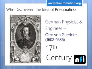
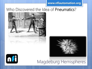
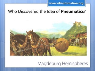
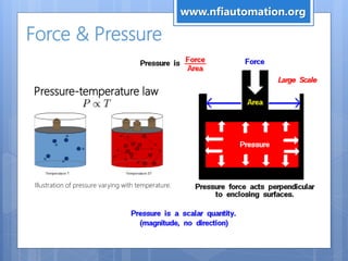
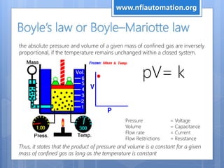
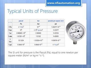
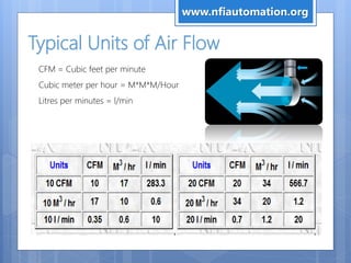
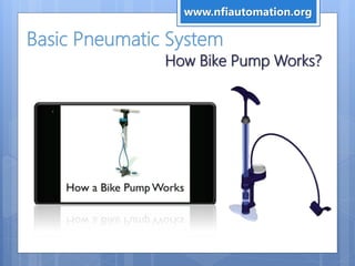
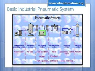
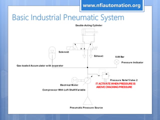
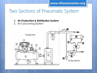
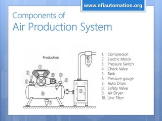
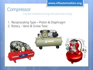
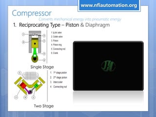
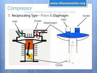
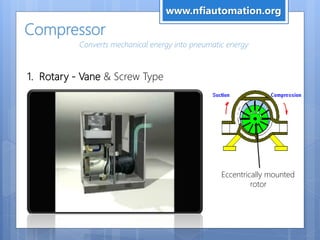


This document provides an overview of pneumatics training. It begins by defining pneumatics as movement by compressed air and describes some common applications in everyday life. It then discusses the history of pneumatics, focusing on Otto von Guericke's experiments with compressed air in the 17th century. The document proceeds to cover pneumatic principles such as pressure, flow rate, and Boyle's law. It provides details on typical pneumatic system components like compressors, cylinders, valves, and applications in automation. Electro-pneumatic systems are also introduced. Exercises in drawing pneumatic circuits are included throughout.


