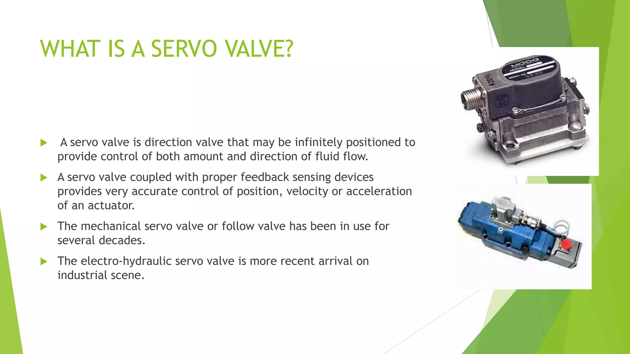
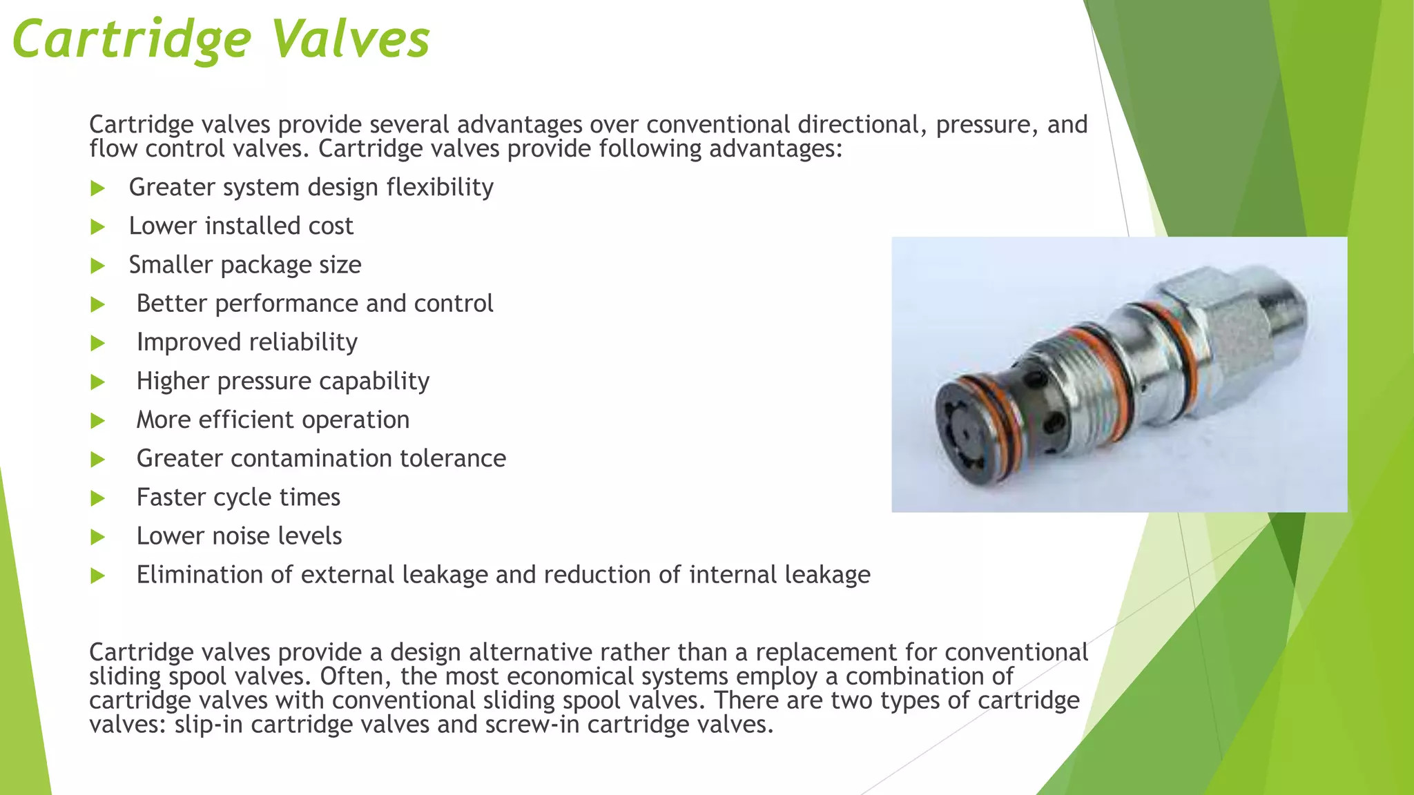
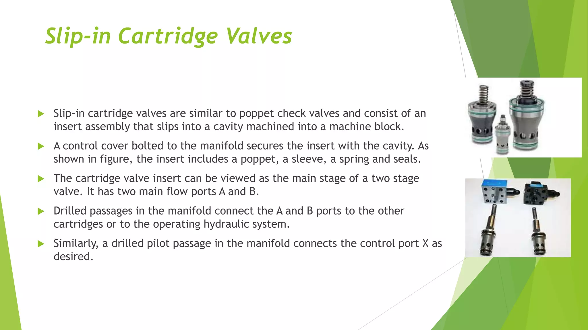
Servo Valves
WHAT IS A SERVO VALVE?
 A servo valve is direction valve that may be infinitely positioned to
provide control of both amount and direction of fluid flow.
 A servo valve coupled with proper feedback sensing devices
provides very accurate control of position, velocity or acceleration
of an actuator.
 The mechanical servo valve or follow valve has been in use for
several decades.
 The electro-hydraulic servo valve is more recent arrival on
industrial scene.
Mechanical Servo Valve
 The Mechanical servo valve is essentially a force amplifier
used for positioning control.
 The mechanical servo valve is often referred to as booster.
 The hydraulic boost is capable of considerably greater force
than mechanical input, with precise control of distance
moved.
 The most significant application of mechanical servo valve is
in power steering.
Working of Mechanical
Servo Valve
 The control handle or other
mechanical linkage is connected to
valve spool.
 The valve body is connected to
controller and moves with load.
When spool is actuated, it allows
flow to cylinder or piston to move
load in same direction as actuated
spool.
 The valve body follows the spool
flow continues until body is
centered or neutral with spool. The
valve body is connected to load.
 The effect is that load always moves
distance proportional to spool
movement. Any tendency to move
further would reverse oil flow,
moving it back into position.
Proportional Valves
 Proportional valve fills the gap between conventional solenoid valves and
servo valves. Like conventional solenoid valve, proportional valve are simple
in design and relatively easy to service.
 However, unlike conventional on/off DC solenoid valves, they can assume an
infinite number of positions within their working range. Proportional valves
have many of control features, without design complexity and high cost, of
more sophisticated servo valves. They are used in applications that require
moderately accurate control of hydraulic fluid.
 Proportional valves control and vary pressure, flow, direction, acceleration
and deceleration from remote position. They are adjusted and are actuated
by proportional solenoid valve that provides remote control of hydraulic flow.
Typically spool is spring centered or spring offset.
Working of Proportional Valves
 On a solenoid, magnetic force is created when current is passed through
solenoid coil. Thos force pulls solenoid armature towards pole piece.
 A push pin attached to armature then transmits force to valve spool.
 The major difference between a proportional solenoid and conventional
on/off solenoid is design of armature, pole piece and core tube assembly.
 The proportional solenoid is shaped in a manner that delivers more constant
force over entire working stroke.
 The coil current alone determines amount of force transmitted to valve spool.
 The solenoid force moves spool until a balance is achieved between solenoid
force and valve spring force.
 By varying current, the solenoid can force spool to assume position anywhere
within its working range.
 This operation is called spring feedback, because valve spring is the only
feedback for solenoid force. Because this operation does not take into
account other forces that might affect spool position (such as frictional and
flow force). It is not appropriate for applications that require a high degree of
value performance
Working of Proportional Valves
Cartridge Valves
Cartridge valves provide several advantages over conventional directional, pressure, and
flow control valves. Cartridge valves provide following advantages:
 Greater system design flexibility
 Lower installed cost
 Smaller package size
 Better performance and control
 Improved reliability
 Higher pressure capability
 More efficient operation
 Greater contamination tolerance
 Faster cycle times
 Lower noise levels
 Elimination of external leakage and reduction of internal leakage
Cartridge valves provide a design alternative rather than a replacement for conventional
sliding spool valves. Often, the most economical systems employ a combination of
cartridge valves with conventional sliding spool valves. There are two types of cartridge
valves: slip-in cartridge valves and screw-in cartridge valves.
Slip-in Cartridge Valves
 Slip-in cartridge valves are similar to poppet check valves and consist of an
insert assembly that slips into a cavity machined into a machine block.
 A control cover bolted to the manifold secures the insert with the cavity. As
shown in figure, the insert includes a poppet, a sleeve, a spring and seals.
 The cartridge valve insert can be viewed as the main stage of a two stage
valve. It has two main flow ports A and B.
 Drilled passages in the manifold connect the A and B ports to the other
cartridges or to the operating hydraulic system.
 Similarly, a drilled pilot passage in the manifold connects the control port X as
desired.
Slip-in Cartridge Valves
 There is an orifice in the drilled
passage between X port and the
spring chamber AP.
 The purpose of this orifice is to
reduce the speed at which the
valve poppet opens and closes.
 Various orifice sizes are available
to optimize or tune the cartridge
response in relation to that of the
entire hydraulic system.
 The designer can select the
orifice size that provides
maximum operating speeds with
minimum hydraulic shocks.

Servo Valves

  • 1.
  • 2.
    WHAT IS ASERVO VALVE?  A servo valve is direction valve that may be infinitely positioned to provide control of both amount and direction of fluid flow.  A servo valve coupled with proper feedback sensing devices provides very accurate control of position, velocity or acceleration of an actuator.  The mechanical servo valve or follow valve has been in use for several decades.  The electro-hydraulic servo valve is more recent arrival on industrial scene.
  • 3.
    Mechanical Servo Valve The Mechanical servo valve is essentially a force amplifier used for positioning control.  The mechanical servo valve is often referred to as booster.  The hydraulic boost is capable of considerably greater force than mechanical input, with precise control of distance moved.  The most significant application of mechanical servo valve is in power steering.
  • 4.
    Working of Mechanical ServoValve  The control handle or other mechanical linkage is connected to valve spool.  The valve body is connected to controller and moves with load. When spool is actuated, it allows flow to cylinder or piston to move load in same direction as actuated spool.  The valve body follows the spool flow continues until body is centered or neutral with spool. The valve body is connected to load.  The effect is that load always moves distance proportional to spool movement. Any tendency to move further would reverse oil flow, moving it back into position.
  • 5.
    Proportional Valves  Proportionalvalve fills the gap between conventional solenoid valves and servo valves. Like conventional solenoid valve, proportional valve are simple in design and relatively easy to service.  However, unlike conventional on/off DC solenoid valves, they can assume an infinite number of positions within their working range. Proportional valves have many of control features, without design complexity and high cost, of more sophisticated servo valves. They are used in applications that require moderately accurate control of hydraulic fluid.  Proportional valves control and vary pressure, flow, direction, acceleration and deceleration from remote position. They are adjusted and are actuated by proportional solenoid valve that provides remote control of hydraulic flow. Typically spool is spring centered or spring offset.
  • 6.
    Working of ProportionalValves  On a solenoid, magnetic force is created when current is passed through solenoid coil. Thos force pulls solenoid armature towards pole piece.  A push pin attached to armature then transmits force to valve spool.  The major difference between a proportional solenoid and conventional on/off solenoid is design of armature, pole piece and core tube assembly.  The proportional solenoid is shaped in a manner that delivers more constant force over entire working stroke.  The coil current alone determines amount of force transmitted to valve spool.  The solenoid force moves spool until a balance is achieved between solenoid force and valve spring force.  By varying current, the solenoid can force spool to assume position anywhere within its working range.  This operation is called spring feedback, because valve spring is the only feedback for solenoid force. Because this operation does not take into account other forces that might affect spool position (such as frictional and flow force). It is not appropriate for applications that require a high degree of value performance
  • 7.
  • 8.
    Cartridge Valves Cartridge valvesprovide several advantages over conventional directional, pressure, and flow control valves. Cartridge valves provide following advantages:  Greater system design flexibility  Lower installed cost  Smaller package size  Better performance and control  Improved reliability  Higher pressure capability  More efficient operation  Greater contamination tolerance  Faster cycle times  Lower noise levels  Elimination of external leakage and reduction of internal leakage Cartridge valves provide a design alternative rather than a replacement for conventional sliding spool valves. Often, the most economical systems employ a combination of cartridge valves with conventional sliding spool valves. There are two types of cartridge valves: slip-in cartridge valves and screw-in cartridge valves.
  • 9.
    Slip-in Cartridge Valves Slip-in cartridge valves are similar to poppet check valves and consist of an insert assembly that slips into a cavity machined into a machine block.  A control cover bolted to the manifold secures the insert with the cavity. As shown in figure, the insert includes a poppet, a sleeve, a spring and seals.  The cartridge valve insert can be viewed as the main stage of a two stage valve. It has two main flow ports A and B.  Drilled passages in the manifold connect the A and B ports to the other cartridges or to the operating hydraulic system.  Similarly, a drilled pilot passage in the manifold connects the control port X as desired.
  • 10.
    Slip-in Cartridge Valves There is an orifice in the drilled passage between X port and the spring chamber AP.  The purpose of this orifice is to reduce the speed at which the valve poppet opens and closes.  Various orifice sizes are available to optimize or tune the cartridge response in relation to that of the entire hydraulic system.  The designer can select the orifice size that provides maximum operating speeds with minimum hydraulic shocks.