The document discusses fundamentals of valves including:
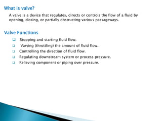
1. Definitions of valves and their basic functions of regulating fluid flow.
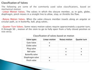
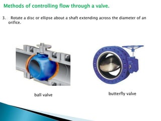
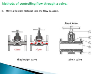
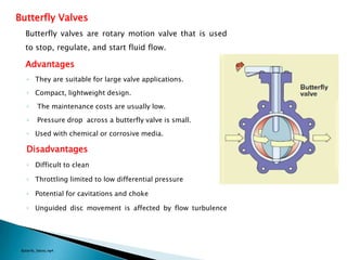
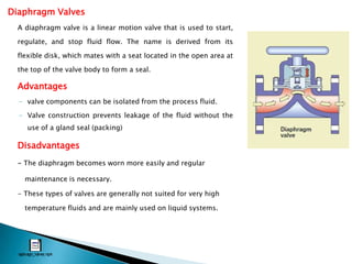
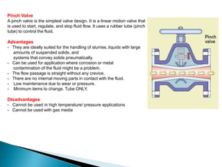
2. Common classifications of valves based on their motion types like linear, rotary, and quarter turn.
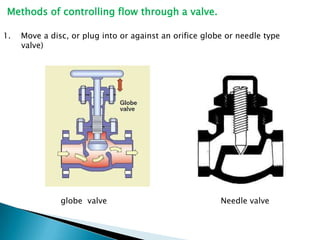
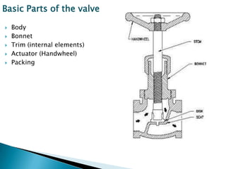
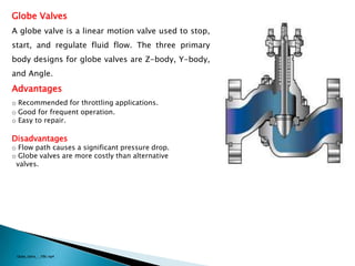
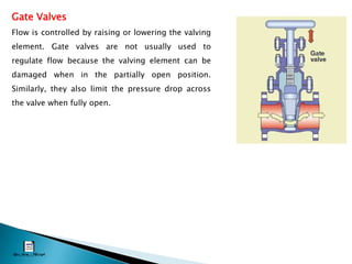
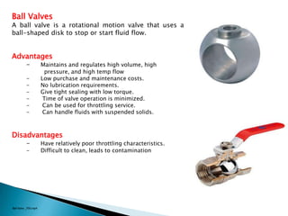
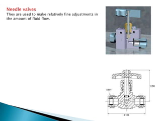
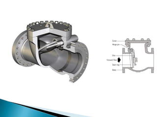
3. Explanations of common valve types like gate valves, globe valves, ball valves and their basic designs and purposes.