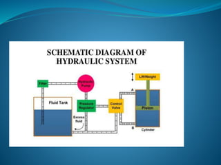
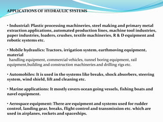
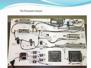
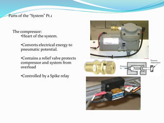
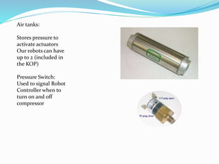
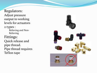
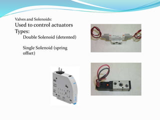
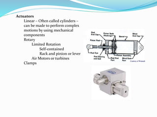
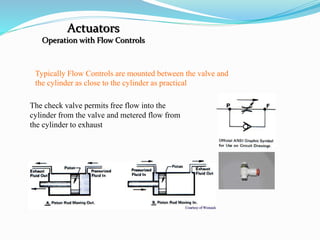
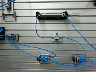
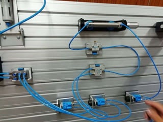
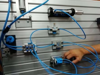
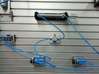
SlideShare a Scribd company logo
1 of 42
Hydraulics and pneumatics
By
K.Nagaraju (15311A03J2)
Hydraulic System
•A Hydraulic System is a power Transmission System in which the
transmission of power takes place through a fluid medium.
•A hydraulic drive system is a quasi-hydrostatic drive or transmission
system that uses pressurized hydraulic fluid to power hydraulic
machinery.
•Hydraulic System is most convenient and efficient System.
PRINCIPLE OF HYDRAULIC SYSTEM
• The Hydraulic System works on the principle of Pascal’s law.
• Pascal’s law states that “The pressure in an enclosed fluid is
uniform in all the directions”.
COMPONENTS OF HYDRAULIC SYSTEM
The major components of a hydraulic system are:
1. Prime Mover
2. Pump
3. Control Valves
4. Actuators(Hydraulic motors, pistons)
5. Piping System
6. Fluid
I. PRIME MOVERS
•Prime mover is a device which develops the mechanical power.
• This power in a hydraulic system is basically used to drive the pump.
• Prime mover includes IC Engine, Turbines, etc
II. HYDRAULIC PUMPS
• Pump is a device which converts mechanical energy to fluid
energy.
• The hydraulic pump takes hydraulic fluid (mostly some oil) from
the storage tank and delivers it to the rest of the hydraulic circuit.
• The hydraulic pumps are characterized by its flow rate capacity,
power , consumption, drive speed, pressure delivered at the outlet
and efficiency of the pump.
TYPES OF HYDRAULIC PUMPS
Non-positive displacement pumps:
•Known as hydro-dynamic pumps
•Fluid is pressurized by the rotation of the propeller and the fluid pressure
is proportional to the rotor speed
•Used for low-pressure and high-volume flow applications
Eg: Centrifugal Pumps
Positive displacement pumps:
•These pumps deliver a constant volume of fluid in a cycle
•Used in most of the industrial fluid power applications
•The output fluid flow is constant and is independent of the system
pressure
•Eg: Vane pump, Piston Pump, Gear Pump
III. CONTROL VALVES
•The control of the mechanical outputs (motion and force) is one of the most
important functions in a hydraulic system.
• The proper selection of control selection ensures the desired output and safe
function of the system.
• In order to control the hydraulic outputs, different types of control valves are
required.
• There are basically three types of valves employed in hydraulic systems:
1. Directional control valves
2. Flow control valves
3. Pressure control valves
DIRECTIONAL CONTROL VALVES
• Directional control valves provide the direction to the fluid and allow
the flow in a particular direction.
• These valves are used to control the start, stop and change in direction
of the fluid flow.
• They can be classified in the following manner:
Type of construction:
1. Poppet valves
2. Spool valves
Number of ports and switching positions:
1. Three way two position
2. Four way three position
3. Four way two position
Method of change over from one position to next:
1. Non throttling type
2. Throttling type
FLOW CONTROL VALVES
• A flow control valve can regulate the flow or pressure of the
fluid.
• The fluid flow is controlled by varying area of the valve
opening through which fluid passes.
IV. HYDRAULIC ACTUATORS
•Hydraulic Actuators employ hydraulic pressure to drive an output member.
• These are used where high speed and large forces are required.
• The fluid used in hydraulic actuator is highly incompressible.
•They convert fluid power into mechanical power.
• Depending on motion they can be classified as:
1. Linear actuators: linear motion as output(cylinder and piston)
2. Rotary actuator: rotary motion as output(motor
V. HYDRAULIC FLUID
•Hydraulic fluid must be essentially non-compressible to be able to
transmit power instantaneously from one part of the system to another.
• At the same time, it should lubricate the moving parts to reduce friction
loss and cool the components so that the heat generated does not lead to
fire hazards.
•The most common liquid used in hydraulic systems is petroleum oil
because it is only very slightly compressible.
Properties of hydraulic fluids:
1. Non compressible
2. Low volatility
3. Corrosion control
4. Fire resistance
5. Low toxicity
6. Good lubricator
VI. FILTERS
The hydraulic fluid is kept clean in the system with the help of filters and
strainers.
• It removes minute particles from the fluid, which can cause blocking of the
orifices of servo-valves or cause jamming of spools.
• Types of hydraulic filters:
1. Suction Filters: The suction filter provides protection to the hydraulic
pump from particles larger than 10 microns.
2. Pressure Side Filters: Located downstream from the hydraulic pump,
these filters are designed to clean the fluid as it exits the pump to
protect more sensitive system components such as control valves and
actuators from
contaminants generated from the pump.
3. Return Side Filter:
Located between the control valve and the fluid reservoir, these filters are
designed to capture wear debris from the hydraulic systems working
components before returning
the fluid back to the reservoir
4.Offline Filter:
These filters are used, independent from the hydraulic system, to clean hydraulic
fluid before it enters
the hydraulic system itself
VII. ACCUMULATORS
•Accumulator are a common part of hydraulic machinery. Their
function is to store energy by using pressurized gas. One type is a
tube with a floating piston. On one side of the piston is a charge of
pressurized gas, and on the other side is the fluid. Bladders are used
in other designs. Reservoirs store a system's fluid.
•Examples of accumulator uses are backup power for steering or
brakes, or to act as a shock absorber for the hydraulic circuit
APPLICATIONS OF HYDRAULIC SYSTEMS
• Industrial: Plastic processing machineries, steel making and primary metal
extraction applications, automated production lines, machine tool industries,
paper industries, loaders, crushes, textile machineries, R & D equipment and
robotic systems etc.
• Mobile hydraulics: Tractors, irrigation system, earthmoving equipment,
material
handling equipment, commercial vehicles, tunnel boring equipment, rail
equipment,building and construction machineries and drilling rigs etc.
• Automobiles: It is used in the systems like breaks, shock absorbers, steering
system, wind shield, lift and cleaning etc.
• Marine applications: It mostly covers ocean going vessels, fishing boats and
navel equipment.
• Aerospace equipment: There are equipment and systems used for rudder
control, landing gear, breaks, flight control and transmission etc. which are
used in airplanes, rockets and spaceships.
Pneumatics
What are Pneumatics
Pneumatics is a type of power transmission that uses a gas
( in our case, air) and pressure differential to create movement.
Akin to Hydraulics, hydraulics use oil, water, or other fluids instead of
gases
A “System” is a complete set of parts working together.
Our systems usually contain :
A compressor
Storage tanks
Regulators
Gauges
Valves and solenoids
Actuators
Fittings and tubing
The Pneumatics System
The Pneumatic System
Parts of the “System” Pt.1
The compressor:
•Heart of the system.
•Converts electrical energy to
pneumatic potential.
•Contains a relief valve protects
compressor and system from
overload
•Controlled by a Spike relay
Air tanks:
Stores pressure to
activate actuators
Our robots can have
up to 2 (included in
the KOP)
Pressure Switch:
Used to signal Robot
Controller when to
turn on and off
compressor
Regulators:
Adjust pressure
output to working
levels for actuators
2 types :
Relieving and Non-
Relieving
Fittings:
Quick release and
pipe thread.
Pipe thread requires
Teflon tape
Valves and Solenoids:
Used to control actuators
Types:
Double Solenoid (detented)
Single Solenoid (spring
offset)
Actuators
Linear – Often called cylinders –
can be made to perform complex
motions by using mechanical
components
Rotary
Limited Rotation
Self-contained
Rack and pinion or lever
Air Motors or turbines
Clamps
Actuators
Operation with Flow Controls
Typically Flow Controls are mounted between the valve and
the cylinder as close to the cylinder as practical
The check valve permits free flow into the
cylinder from the valve and metered flow from
the cylinder to exhaust
Hydraulic control system

More Related Content

What's hot

Pneumatic circuits
Pneumatic circuitsPneumatic circuits
Pneumatic circuitsRAHUL THAKER
 
Module 5 hydraulics and pneumatics Actuation systems
Module 5 hydraulics and pneumatics Actuation systemsModule 5 hydraulics and pneumatics Actuation systems
Module 5 hydraulics and pneumatics Actuation systemstaruian
 
Introduction to Pneumatic Systems
Introduction to Pneumatic SystemsIntroduction to Pneumatic Systems
Introduction to Pneumatic SystemsRAHUL THAKER
 
Hydraulic Maintenance and Troubleshooting
Hydraulic Maintenance and TroubleshootingHydraulic Maintenance and Troubleshooting
Hydraulic Maintenance and TroubleshootingCMA/Flodyne/Hydradyne
 
PLC (PROGRAMMABLE LOGIC CONTROLLER)
PLC (PROGRAMMABLE LOGIC CONTROLLER)PLC (PROGRAMMABLE LOGIC CONTROLLER)
PLC (PROGRAMMABLE LOGIC CONTROLLER)Manoj Gowda K
 
Hydraulic Valves (Valves) (Pneumatics also)
Hydraulic Valves (Valves) (Pneumatics also)Hydraulic Valves (Valves) (Pneumatics also)
Hydraulic Valves (Valves) (Pneumatics also)Mohammad Azam Khan
 
pneumatic and hydraulic symbols
pneumatic and hydraulic symbolspneumatic and hydraulic symbols
pneumatic and hydraulic symbolsShrenik Baid
 
A presentation on scada system
A presentation on scada systemA presentation on scada system
A presentation on scada systemIIT INDORE
 
Fundamental of hydraulic components
Fundamental of hydraulic componentsFundamental of hydraulic components
Fundamental of hydraulic componentsPrasadroshan Mythin
 
Components of pneumatic system
Components of pneumatic systemComponents of pneumatic system
Components of pneumatic systemJAYDEV PATEL
 
Hydraulic Valves and Hydraulic System Accessories
Hydraulic Valves and Hydraulic System AccessoriesHydraulic Valves and Hydraulic System Accessories
Hydraulic Valves and Hydraulic System AccessoriesRAHUL THAKER
 
02 3 prime-movers
02 3 prime-movers02 3 prime-movers
02 3 prime-moversSatya Verma
 

What's hot (20)

Basic hydraulic circuit
Basic hydraulic circuitBasic hydraulic circuit
Basic hydraulic circuit
 
Pneumatic circuits
Pneumatic circuitsPneumatic circuits
Pneumatic circuits
 
Module 5 hydraulics and pneumatics Actuation systems
Module 5 hydraulics and pneumatics Actuation systemsModule 5 hydraulics and pneumatics Actuation systems
Module 5 hydraulics and pneumatics Actuation systems
 
Introduction to Pneumatic Systems
Introduction to Pneumatic SystemsIntroduction to Pneumatic Systems
Introduction to Pneumatic Systems
 
Hydraulic Maintenance and Troubleshooting
Hydraulic Maintenance and TroubleshootingHydraulic Maintenance and Troubleshooting
Hydraulic Maintenance and Troubleshooting
 
PLC (PROGRAMMABLE LOGIC CONTROLLER)
PLC (PROGRAMMABLE LOGIC CONTROLLER)PLC (PROGRAMMABLE LOGIC CONTROLLER)
PLC (PROGRAMMABLE LOGIC CONTROLLER)
 
Hydraulic Pumps
Hydraulic PumpsHydraulic Pumps
Hydraulic Pumps
 
Hydraulic Valves (Valves) (Pneumatics also)
Hydraulic Valves (Valves) (Pneumatics also)Hydraulic Valves (Valves) (Pneumatics also)
Hydraulic Valves (Valves) (Pneumatics also)
 
Actuators.ppt
Actuators.pptActuators.ppt
Actuators.ppt
 
pneumatic and hydraulic symbols
pneumatic and hydraulic symbolspneumatic and hydraulic symbols
pneumatic and hydraulic symbols
 
Actuators
ActuatorsActuators
Actuators
 
Scada ppt
Scada  pptScada  ppt
Scada ppt
 
A presentation on scada system
A presentation on scada systemA presentation on scada system
A presentation on scada system
 
Fundamental of hydraulic components
Fundamental of hydraulic componentsFundamental of hydraulic components
Fundamental of hydraulic components
 
Pneumatic systems
Pneumatic systemsPneumatic systems
Pneumatic systems
 
ppt on PLC
ppt on PLCppt on PLC
ppt on PLC
 
Components of pneumatic system
Components of pneumatic systemComponents of pneumatic system
Components of pneumatic system
 
Hydraulic Valves and Hydraulic System Accessories
Hydraulic Valves and Hydraulic System AccessoriesHydraulic Valves and Hydraulic System Accessories
Hydraulic Valves and Hydraulic System Accessories
 
02 3 prime-movers
02 3 prime-movers02 3 prime-movers
02 3 prime-movers
 
Hydraulic systems
Hydraulic  systemsHydraulic  systems
Hydraulic systems
 

Similar to Hydraulic control system

2 hydraulic motor and control component
2 hydraulic motor and control component2 hydraulic motor and control component
2 hydraulic motor and control componentDr.R. SELVAM
 
MCE416 Fluid power system lecture note Lecture note.pptx
MCE416 Fluid power system lecture note Lecture note.pptxMCE416 Fluid power system lecture note Lecture note.pptx
MCE416 Fluid power system lecture note Lecture note.pptxDavidPeaceAchebe
 
Components of hydraulic & pneumetic
Components of hydraulic & pneumeticComponents of hydraulic & pneumetic
Components of hydraulic & pneumeticShivji Dangar
 
Components of hydraulic system
Components of hydraulic systemComponents of hydraulic system
Components of hydraulic systemJAYDEV PATEL
 
Ce.pptx 2
Ce.pptx 2Ce.pptx 2
Ce.pptx 2Hrdbs
 
lecture-1.ppt
lecture-1.pptlecture-1.ppt
lecture-1.pptpiko19
 
Hydraulic control system
Hydraulic control systemHydraulic control system
Hydraulic control systemDhavalkumar R
 
Basic hydraulics
Basic hydraulicsBasic hydraulics
Basic hydraulicsPINAKI ROY
 
Fluid Mechanics and neumatics Engineering third module
Fluid Mechanics and neumatics Engineering third module Fluid Mechanics and neumatics Engineering third module
Fluid Mechanics and neumatics Engineering third module Abhinand72
 
Unit – 2 hydraulic, pneumaic and electrical telemetry systems
Unit – 2    hydraulic, pneumaic and electrical telemetry systemsUnit – 2    hydraulic, pneumaic and electrical telemetry systems
Unit – 2 hydraulic, pneumaic and electrical telemetry systemshiya123jes
 
Fluid Power and Control-lecture 1.pptx
Fluid Power and Control-lecture 1.pptxFluid Power and Control-lecture 1.pptx
Fluid Power and Control-lecture 1.pptxKIJAMALEGI
 
Chapter_4_HYDRAULIC final ppt presentation
Chapter_4_HYDRAULIC final ppt presentationChapter_4_HYDRAULIC final ppt presentation
Chapter_4_HYDRAULIC final ppt presentationsrajece
 
Designing of hydraulic system
Designing of hydraulic systemDesigning of hydraulic system
Designing of hydraulic systemSHAH HET
 
Section 3 adv 12
Section 3 adv 12Section 3 adv 12
Section 3 adv 12CDI Aljeer
 
Hydraulic System of Aircrafts
Hydraulic System of AircraftsHydraulic System of Aircrafts
Hydraulic System of Aircraftsalpha_sherdil
 

Similar to Hydraulic control system (20)

Hydraulic control system
Hydraulic control systemHydraulic control system
Hydraulic control system
 
2 hydraulic motor and control component
2 hydraulic motor and control component2 hydraulic motor and control component
2 hydraulic motor and control component
 
MCE416 Fluid power system lecture note Lecture note.pptx
MCE416 Fluid power system lecture note Lecture note.pptxMCE416 Fluid power system lecture note Lecture note.pptx
MCE416 Fluid power system lecture note Lecture note.pptx
 
Components of hydraulic & pneumetic
Components of hydraulic & pneumeticComponents of hydraulic & pneumetic
Components of hydraulic & pneumetic
 
Components of hydraulic system
Components of hydraulic systemComponents of hydraulic system
Components of hydraulic system
 
Ce.pptx 2
Ce.pptx 2Ce.pptx 2
Ce.pptx 2
 
lecture-1.ppt
lecture-1.pptlecture-1.ppt
lecture-1.ppt
 
lecture-1.ppt
lecture-1.pptlecture-1.ppt
lecture-1.ppt
 
lecture-1.ppt
lecture-1.pptlecture-1.ppt
lecture-1.ppt
 
Hydraulic control system
Hydraulic control systemHydraulic control system
Hydraulic control system
 
Basic hydraulics
Basic hydraulicsBasic hydraulics
Basic hydraulics
 
Fluid Mechanics and neumatics Engineering third module
Fluid Mechanics and neumatics Engineering third module Fluid Mechanics and neumatics Engineering third module
Fluid Mechanics and neumatics Engineering third module
 
Unit – 2 hydraulic, pneumaic and electrical telemetry systems
Unit – 2    hydraulic, pneumaic and electrical telemetry systemsUnit – 2    hydraulic, pneumaic and electrical telemetry systems
Unit – 2 hydraulic, pneumaic and electrical telemetry systems
 
Fluid Power and Control-lecture 1.pptx
Fluid Power and Control-lecture 1.pptxFluid Power and Control-lecture 1.pptx
Fluid Power and Control-lecture 1.pptx
 
Chapter_4_HYDRAULIC final ppt presentation
Chapter_4_HYDRAULIC final ppt presentationChapter_4_HYDRAULIC final ppt presentation
Chapter_4_HYDRAULIC final ppt presentation
 
Mine mechanisation 1
Mine mechanisation 1Mine mechanisation 1
Mine mechanisation 1
 
Designing of hydraulic system
Designing of hydraulic systemDesigning of hydraulic system
Designing of hydraulic system
 
Section 3 adv 12
Section 3 adv 12Section 3 adv 12
Section 3 adv 12
 
Hydraulic System of Aircrafts
Hydraulic System of AircraftsHydraulic System of Aircrafts
Hydraulic System of Aircrafts
 
MEKATRONIKA Aktuator.pptx
MEKATRONIKA Aktuator.pptxMEKATRONIKA Aktuator.pptx
MEKATRONIKA Aktuator.pptx
 

More from nagaraju kondrasi

More from nagaraju kondrasi (7)

aqua silencer report
aqua silencer report aqua silencer report
aqua silencer report
 
Hydraulic systems report
Hydraulic systems  reportHydraulic systems  report
Hydraulic systems report
 
1 pneumatics theory & practical copy
1 pneumatics theory &  practical   copy1 pneumatics theory &  practical   copy
1 pneumatics theory & practical copy
 
Rack and pinion analysis
Rack and pinion analysisRack and pinion analysis
Rack and pinion analysis
 
Analysis of Rack and Pinion under dynamic conditions
Analysis of Rack and Pinion under dynamic conditionsAnalysis of Rack and Pinion under dynamic conditions
Analysis of Rack and Pinion under dynamic conditions
 
Crystal structure
Crystal structureCrystal structure
Crystal structure
 
Green chemistry
Green chemistryGreen chemistry
Green chemistry
 

Recently uploaded

Why does (not) Kafka need fsync: Eliminating tail latency spikes caused by fsync
Why does (not) Kafka need fsync: Eliminating tail latency spikes caused by fsyncWhy does (not) Kafka need fsync: Eliminating tail latency spikes caused by fsync
Why does (not) Kafka need fsync: Eliminating tail latency spikes caused by fsyncssuser2ae721
 
Concrete Mix Design - IS 10262-2019 - .pptx
Concrete Mix Design - IS 10262-2019 - .pptxConcrete Mix Design - IS 10262-2019 - .pptx
Concrete Mix Design - IS 10262-2019 - .pptxKartikeyaDwivedi3
 
Gfe Mayur Vihar Call Girls Service WhatsApp -> 9999965857 Available 24x7 ^ De...
Gfe Mayur Vihar Call Girls Service WhatsApp -> 9999965857 Available 24x7 ^ De...Gfe Mayur Vihar Call Girls Service WhatsApp -> 9999965857 Available 24x7 ^ De...
Gfe Mayur Vihar Call Girls Service WhatsApp -> 9999965857 Available 24x7 ^ De...srsj9000
 
Call Us ≽ 8377877756 ≼ Call Girls In Shastri Nagar (Delhi)
Call Us ≽ 8377877756 ≼ Call Girls In Shastri Nagar (Delhi)Call Us ≽ 8377877756 ≼ Call Girls In Shastri Nagar (Delhi)
Call Us ≽ 8377877756 ≼ Call Girls In Shastri Nagar (Delhi)dollysharma2066
 
Call Girls Delhi {Jodhpur} 9711199012 high profile service
Call Girls Delhi {Jodhpur} 9711199012 high profile serviceCall Girls Delhi {Jodhpur} 9711199012 high profile service
Call Girls Delhi {Jodhpur} 9711199012 high profile servicerehmti665
 
What are the advantages and disadvantages of membrane structures.pptx
What are the advantages and disadvantages of membrane structures.pptxWhat are the advantages and disadvantages of membrane structures.pptx
What are the advantages and disadvantages of membrane structures.pptxwendy cai
 
Application of Residue Theorem to evaluate real integrations.pptx
Application of Residue Theorem to evaluate real integrations.pptxApplication of Residue Theorem to evaluate real integrations.pptx
Application of Residue Theorem to evaluate real integrations.pptx959SahilShah
 
Oxy acetylene welding presentation note.
Oxy acetylene welding presentation note.Oxy acetylene welding presentation note.
Oxy acetylene welding presentation note.eptoze12
 
CCS355 Neural Network & Deep Learning UNIT III notes and Question bank .pdf
CCS355 Neural Network & Deep Learning UNIT III notes and Question bank .pdfCCS355 Neural Network & Deep Learning UNIT III notes and Question bank .pdf
CCS355 Neural Network & Deep Learning UNIT III notes and Question bank .pdfAsst.prof M.Gokilavani
 
Churning of Butter, Factors affecting .
Churning of Butter, Factors affecting  .Churning of Butter, Factors affecting  .
Churning of Butter, Factors affecting .Satyam Kumar
 
Past, Present and Future of Generative AI
Past, Present and Future of Generative AIPast, Present and Future of Generative AI
Past, Present and Future of Generative AIabhishek36461
 
Risk Assessment For Installation of Drainage Pipes.pdf
Risk Assessment For Installation of Drainage Pipes.pdfRisk Assessment For Installation of Drainage Pipes.pdf
Risk Assessment For Installation of Drainage Pipes.pdfROCENODodongVILLACER
 
Gurgaon ✡️9711147426✨Call In girls Gurgaon Sector 51 escort service
Gurgaon ✡️9711147426✨Call In girls Gurgaon Sector 51 escort serviceGurgaon ✡️9711147426✨Call In girls Gurgaon Sector 51 escort service
Gurgaon ✡️9711147426✨Call In girls Gurgaon Sector 51 escort servicejennyeacort
 
CCS355 Neural Networks & Deep Learning Unit 1 PDF notes with Question bank .pdf
CCS355 Neural Networks & Deep Learning Unit 1 PDF notes with Question bank .pdfCCS355 Neural Networks & Deep Learning Unit 1 PDF notes with Question bank .pdf
CCS355 Neural Networks & Deep Learning Unit 1 PDF notes with Question bank .pdfAsst.prof M.Gokilavani
 
Biology for Computer Engineers Course Handout.pptx
Biology for Computer Engineers Course Handout.pptxBiology for Computer Engineers Course Handout.pptx
Biology for Computer Engineers Course Handout.pptxDeepakSakkari2
 
Architect Hassan Khalil Portfolio for 2024
Architect Hassan Khalil Portfolio for 2024Architect Hassan Khalil Portfolio for 2024
Architect Hassan Khalil Portfolio for 2024hassan khalil
 

Recently uploaded (20)

Why does (not) Kafka need fsync: Eliminating tail latency spikes caused by fsync
Why does (not) Kafka need fsync: Eliminating tail latency spikes caused by fsyncWhy does (not) Kafka need fsync: Eliminating tail latency spikes caused by fsync
Why does (not) Kafka need fsync: Eliminating tail latency spikes caused by fsync
 
Design and analysis of solar grass cutter.pdf
Design and analysis of solar grass cutter.pdfDesign and analysis of solar grass cutter.pdf
Design and analysis of solar grass cutter.pdf
 
Concrete Mix Design - IS 10262-2019 - .pptx
Concrete Mix Design - IS 10262-2019 - .pptxConcrete Mix Design - IS 10262-2019 - .pptx
Concrete Mix Design - IS 10262-2019 - .pptx
 
Gfe Mayur Vihar Call Girls Service WhatsApp -> 9999965857 Available 24x7 ^ De...
Gfe Mayur Vihar Call Girls Service WhatsApp -> 9999965857 Available 24x7 ^ De...Gfe Mayur Vihar Call Girls Service WhatsApp -> 9999965857 Available 24x7 ^ De...
Gfe Mayur Vihar Call Girls Service WhatsApp -> 9999965857 Available 24x7 ^ De...
 
9953056974 Call Girls In South Ex, Escorts (Delhi) NCR.pdf
9953056974 Call Girls In South Ex, Escorts (Delhi) NCR.pdf9953056974 Call Girls In South Ex, Escorts (Delhi) NCR.pdf
9953056974 Call Girls In South Ex, Escorts (Delhi) NCR.pdf
 
Call Us ≽ 8377877756 ≼ Call Girls In Shastri Nagar (Delhi)
Call Us ≽ 8377877756 ≼ Call Girls In Shastri Nagar (Delhi)Call Us ≽ 8377877756 ≼ Call Girls In Shastri Nagar (Delhi)
Call Us ≽ 8377877756 ≼ Call Girls In Shastri Nagar (Delhi)
 
Call Girls Delhi {Jodhpur} 9711199012 high profile service
Call Girls Delhi {Jodhpur} 9711199012 high profile serviceCall Girls Delhi {Jodhpur} 9711199012 high profile service
Call Girls Delhi {Jodhpur} 9711199012 high profile service
 
What are the advantages and disadvantages of membrane structures.pptx
What are the advantages and disadvantages of membrane structures.pptxWhat are the advantages and disadvantages of membrane structures.pptx
What are the advantages and disadvantages of membrane structures.pptx
 
Application of Residue Theorem to evaluate real integrations.pptx
Application of Residue Theorem to evaluate real integrations.pptxApplication of Residue Theorem to evaluate real integrations.pptx
Application of Residue Theorem to evaluate real integrations.pptx
 
Oxy acetylene welding presentation note.
Oxy acetylene welding presentation note.Oxy acetylene welding presentation note.
Oxy acetylene welding presentation note.
 
CCS355 Neural Network & Deep Learning UNIT III notes and Question bank .pdf
CCS355 Neural Network & Deep Learning UNIT III notes and Question bank .pdfCCS355 Neural Network & Deep Learning UNIT III notes and Question bank .pdf
CCS355 Neural Network & Deep Learning UNIT III notes and Question bank .pdf
 
Call Us -/9953056974- Call Girls In Vikaspuri-/- Delhi NCR
Call Us -/9953056974- Call Girls In Vikaspuri-/- Delhi NCRCall Us -/9953056974- Call Girls In Vikaspuri-/- Delhi NCR
Call Us -/9953056974- Call Girls In Vikaspuri-/- Delhi NCR
 
Churning of Butter, Factors affecting .
Churning of Butter, Factors affecting  .Churning of Butter, Factors affecting  .
Churning of Butter, Factors affecting .
 
Past, Present and Future of Generative AI
Past, Present and Future of Generative AIPast, Present and Future of Generative AI
Past, Present and Future of Generative AI
 
Risk Assessment For Installation of Drainage Pipes.pdf
Risk Assessment For Installation of Drainage Pipes.pdfRisk Assessment For Installation of Drainage Pipes.pdf
Risk Assessment For Installation of Drainage Pipes.pdf
 
Gurgaon ✡️9711147426✨Call In girls Gurgaon Sector 51 escort service
Gurgaon ✡️9711147426✨Call In girls Gurgaon Sector 51 escort serviceGurgaon ✡️9711147426✨Call In girls Gurgaon Sector 51 escort service
Gurgaon ✡️9711147426✨Call In girls Gurgaon Sector 51 escort service
 
CCS355 Neural Networks & Deep Learning Unit 1 PDF notes with Question bank .pdf
CCS355 Neural Networks & Deep Learning Unit 1 PDF notes with Question bank .pdfCCS355 Neural Networks & Deep Learning Unit 1 PDF notes with Question bank .pdf
CCS355 Neural Networks & Deep Learning Unit 1 PDF notes with Question bank .pdf
 
Biology for Computer Engineers Course Handout.pptx
Biology for Computer Engineers Course Handout.pptxBiology for Computer Engineers Course Handout.pptx
Biology for Computer Engineers Course Handout.pptx
 
POWER SYSTEMS-1 Complete notes examples
POWER SYSTEMS-1 Complete notes  examplesPOWER SYSTEMS-1 Complete notes  examples
POWER SYSTEMS-1 Complete notes examples
 
Architect Hassan Khalil Portfolio for 2024
Architect Hassan Khalil Portfolio for 2024Architect Hassan Khalil Portfolio for 2024
Architect Hassan Khalil Portfolio for 2024
 

Hydraulic control system

  • 2. Hydraulic System •A Hydraulic System is a power Transmission System in which the transmission of power takes place through a fluid medium. •A hydraulic drive system is a quasi-hydrostatic drive or transmission system that uses pressurized hydraulic fluid to power hydraulic machinery. •Hydraulic System is most convenient and efficient System.
  • 3. PRINCIPLE OF HYDRAULIC SYSTEM • The Hydraulic System works on the principle of Pascal’s law. • Pascal’s law states that “The pressure in an enclosed fluid is uniform in all the directions”.
  • 4. COMPONENTS OF HYDRAULIC SYSTEM The major components of a hydraulic system are: 1. Prime Mover 2. Pump 3. Control Valves 4. Actuators(Hydraulic motors, pistons) 5. Piping System 6. Fluid
  • 5.
  • 6. I. PRIME MOVERS •Prime mover is a device which develops the mechanical power. • This power in a hydraulic system is basically used to drive the pump. • Prime mover includes IC Engine, Turbines, etc
  • 7.
  • 8. II. HYDRAULIC PUMPS • Pump is a device which converts mechanical energy to fluid energy. • The hydraulic pump takes hydraulic fluid (mostly some oil) from the storage tank and delivers it to the rest of the hydraulic circuit. • The hydraulic pumps are characterized by its flow rate capacity, power , consumption, drive speed, pressure delivered at the outlet and efficiency of the pump.
  • 9.
  • 10. TYPES OF HYDRAULIC PUMPS Non-positive displacement pumps: •Known as hydro-dynamic pumps •Fluid is pressurized by the rotation of the propeller and the fluid pressure is proportional to the rotor speed •Used for low-pressure and high-volume flow applications Eg: Centrifugal Pumps Positive displacement pumps: •These pumps deliver a constant volume of fluid in a cycle •Used in most of the industrial fluid power applications •The output fluid flow is constant and is independent of the system pressure •Eg: Vane pump, Piston Pump, Gear Pump
  • 11.
  • 12.
  • 13. III. CONTROL VALVES •The control of the mechanical outputs (motion and force) is one of the most important functions in a hydraulic system. • The proper selection of control selection ensures the desired output and safe function of the system. • In order to control the hydraulic outputs, different types of control valves are required. • There are basically three types of valves employed in hydraulic systems: 1. Directional control valves 2. Flow control valves 3. Pressure control valves
  • 14. DIRECTIONAL CONTROL VALVES • Directional control valves provide the direction to the fluid and allow the flow in a particular direction. • These valves are used to control the start, stop and change in direction of the fluid flow. • They can be classified in the following manner: Type of construction: 1. Poppet valves 2. Spool valves Number of ports and switching positions: 1. Three way two position 2. Four way three position 3. Four way two position Method of change over from one position to next: 1. Non throttling type 2. Throttling type
  • 15. FLOW CONTROL VALVES • A flow control valve can regulate the flow or pressure of the fluid. • The fluid flow is controlled by varying area of the valve opening through which fluid passes.
  • 16. IV. HYDRAULIC ACTUATORS •Hydraulic Actuators employ hydraulic pressure to drive an output member. • These are used where high speed and large forces are required. • The fluid used in hydraulic actuator is highly incompressible. •They convert fluid power into mechanical power. • Depending on motion they can be classified as: 1. Linear actuators: linear motion as output(cylinder and piston) 2. Rotary actuator: rotary motion as output(motor
  • 17. V. HYDRAULIC FLUID •Hydraulic fluid must be essentially non-compressible to be able to transmit power instantaneously from one part of the system to another. • At the same time, it should lubricate the moving parts to reduce friction loss and cool the components so that the heat generated does not lead to fire hazards. •The most common liquid used in hydraulic systems is petroleum oil because it is only very slightly compressible. Properties of hydraulic fluids: 1. Non compressible 2. Low volatility 3. Corrosion control 4. Fire resistance 5. Low toxicity 6. Good lubricator
  • 18. VI. FILTERS The hydraulic fluid is kept clean in the system with the help of filters and strainers. • It removes minute particles from the fluid, which can cause blocking of the orifices of servo-valves or cause jamming of spools. • Types of hydraulic filters: 1. Suction Filters: The suction filter provides protection to the hydraulic pump from particles larger than 10 microns. 2. Pressure Side Filters: Located downstream from the hydraulic pump, these filters are designed to clean the fluid as it exits the pump to protect more sensitive system components such as control valves and actuators from contaminants generated from the pump.
  • 19. 3. Return Side Filter: Located between the control valve and the fluid reservoir, these filters are designed to capture wear debris from the hydraulic systems working components before returning the fluid back to the reservoir 4.Offline Filter: These filters are used, independent from the hydraulic system, to clean hydraulic fluid before it enters the hydraulic system itself
  • 20. VII. ACCUMULATORS •Accumulator are a common part of hydraulic machinery. Their function is to store energy by using pressurized gas. One type is a tube with a floating piston. On one side of the piston is a charge of pressurized gas, and on the other side is the fluid. Bladders are used in other designs. Reservoirs store a system's fluid. •Examples of accumulator uses are backup power for steering or brakes, or to act as a shock absorber for the hydraulic circuit
  • 21. APPLICATIONS OF HYDRAULIC SYSTEMS • Industrial: Plastic processing machineries, steel making and primary metal extraction applications, automated production lines, machine tool industries, paper industries, loaders, crushes, textile machineries, R & D equipment and robotic systems etc. • Mobile hydraulics: Tractors, irrigation system, earthmoving equipment, material handling equipment, commercial vehicles, tunnel boring equipment, rail equipment,building and construction machineries and drilling rigs etc. • Automobiles: It is used in the systems like breaks, shock absorbers, steering system, wind shield, lift and cleaning etc. • Marine applications: It mostly covers ocean going vessels, fishing boats and navel equipment. • Aerospace equipment: There are equipment and systems used for rudder control, landing gear, breaks, flight control and transmission etc. which are used in airplanes, rockets and spaceships.
  • 23. What are Pneumatics Pneumatics is a type of power transmission that uses a gas ( in our case, air) and pressure differential to create movement. Akin to Hydraulics, hydraulics use oil, water, or other fluids instead of gases
  • 24. A “System” is a complete set of parts working together. Our systems usually contain : A compressor Storage tanks Regulators Gauges Valves and solenoids Actuators Fittings and tubing The Pneumatics System
  • 26. Parts of the “System” Pt.1 The compressor: •Heart of the system. •Converts electrical energy to pneumatic potential. •Contains a relief valve protects compressor and system from overload •Controlled by a Spike relay
  • 27. Air tanks: Stores pressure to activate actuators Our robots can have up to 2 (included in the KOP) Pressure Switch: Used to signal Robot Controller when to turn on and off compressor
  • 28. Regulators: Adjust pressure output to working levels for actuators 2 types : Relieving and Non- Relieving Fittings: Quick release and pipe thread. Pipe thread requires Teflon tape
  • 29. Valves and Solenoids: Used to control actuators Types: Double Solenoid (detented) Single Solenoid (spring offset)
  • 30. Actuators Linear – Often called cylinders – can be made to perform complex motions by using mechanical components Rotary Limited Rotation Self-contained Rack and pinion or lever Air Motors or turbines Clamps
  • 31. Actuators Operation with Flow Controls Typically Flow Controls are mounted between the valve and the cylinder as close to the cylinder as practical The check valve permits free flow into the cylinder from the valve and metered flow from the cylinder to exhaust