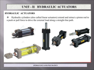
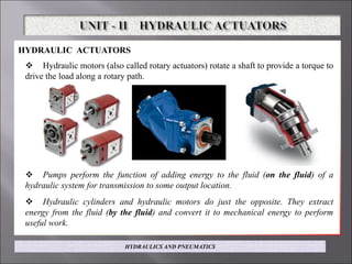
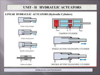
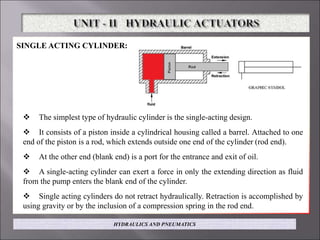
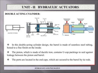
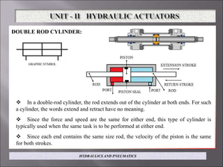
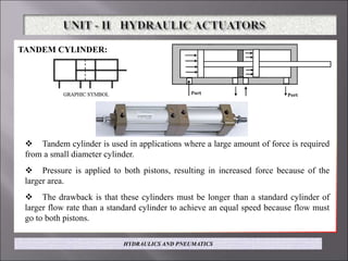
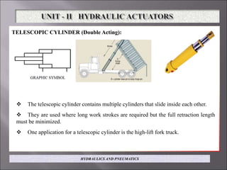
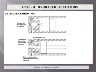
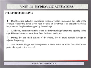
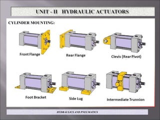
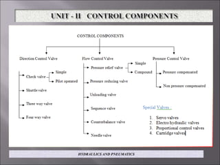
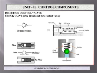
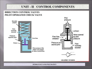
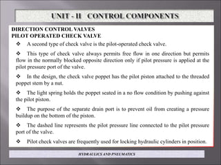
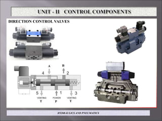
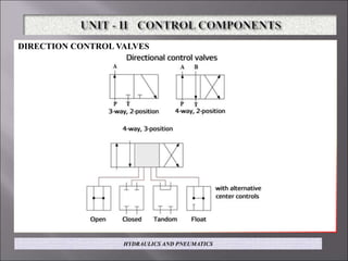
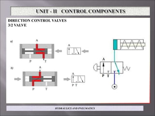
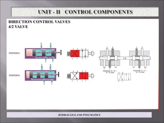
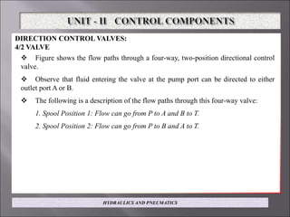
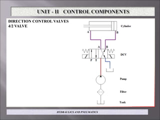
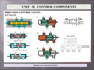
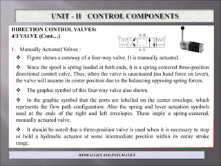
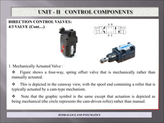
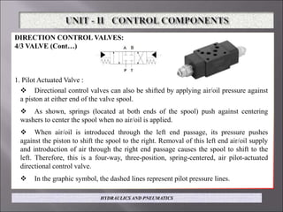
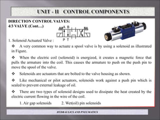
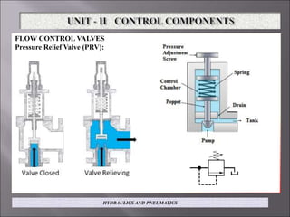
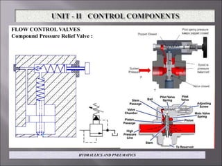
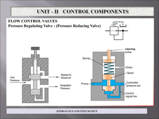
SlideShare a Scribd company logo
By,
Mr.Vimal raja M
Assistant Professor
Dept.of.Mech.Engg.,
KIT-CBE.
HYDRAULICS AND PNEUMATICS
OBJECTIVES: L T P C
3 0 0 3
 To provide student with knowledge on the application of fluid power in process,
construction and manufacturing industries.
 To provide students with an understanding of the fluids and components utilized in
modern industrial fluid power system.
 To develop a measurable degree of competence in the design, construction and
operation of fluid power circuits.
HYDRAULICS AND PNEUMATICS
UNIT II
HYDRAULIC ACTUATORS AND CONTROL COMPONENTS
Hydraulic Actuators: Cylinders – Types and construction, Application, Hydraulic
cushioning – Hydraulic motors - Control Components : Direction Control, Flow control
and pressure control valves – Types, Construction and Operation – Servo and Proportional
valves – Applications – Accessories : Reservoirs, Pressure Switches – Applications –
Fluid Power ANSI Symbols – Problems.
HYDRAULICS AND PNEUMATICS
HYDRAULIC ACTUATORS
 Hydraulic cylinders (also called linear actuators) extend and retract a piston rod to
a push or pull force to drive the external load along a straight-line path.
HYDRAULICS AND PNEUMATICS
HYDRAULIC ACTUATORS
 Hydraulic motors (also called rotary actuators) rotate a shaft to provide a torque to
drive the load along a rotary path.
 Pumps perform the function of adding energy to the fluid (on the fluid) of a
hydraulic system for transmission to some output location.
 Hydraulic cylinders and hydraulic motors do just the opposite. They extract
energy from the fluid (by the fluid) and convert it to mechanical energy to perform
useful work.
HYDRAULICS AND PNEUMATICS
LINEAR HYDRAULIC ACTUATORS (Hydraulic Cylinders)
HYDRAULICS AND PNEUMATICS
SINGLE ACTING CYLINDER:
 The simplest type of hydraulic cylinder is the single-acting design.
 It consists of a piston inside a cylindrical housing called a barrel. Attached to one
end of the piston is a rod, which extends outside one end of the cylinder (rod end).
 At the other end (blank end) is a port for the entrance and exit of oil.
 A single-acting cylinder can exert a force in only the extending direction as fluid
from the pump enters the blank end of the cylinder.
 Single acting cylinders do not retract hydraulically. Retraction is accomplished by
using gravity or by the inclusion of a compression spring in the rod end.
HYDRAULICS AND PNEUMATICS
DOUBLE ACTING CYLINDER:
 In this double-acting cylinder design, the barrel is made of seamless steel tubing,
honed to a fine finish on the inside.
 The piston, which is made of ductile iron, contains U-cup packings to seal against
leakage between the piston and barrel.
 The ports are located in the end caps, which are secured to the barrel by tie rods.
HYDRAULICS AND PNEUMATICS
DOUBLE ROD CYLINDER:
 In a double-rod cylinder, the rod extends out of the cylinder at both ends. For such
a cylinder, the words extend and retract have no meaning.
 Since the force and speed are the same for either end, this type of cylinder is
typically used when the same task is to be performed at either end.
 Since each end contains the same size rod, the velocity of the piston is the same
for both strokes.
HYDRAULICS AND PNEUMATICS
TANDEM CYLINDER:
 Tandem cylinder is used in applications where a large amount of force is required
from a small diameter cylinder.
 Pressure is applied to both pistons, resulting in increased force because of the
larger area.
 The drawback is that these cylinders must be longer than a standard cylinder of
larger flow rate than a standard cylinder to achieve an equal speed because flow must
go to both pistons.
HYDRAULICS AND PNEUMATICS
TELESCOPIC CYLINDER (Double Acting):
 The telescopic cylinder contains multiple cylinders that slide inside each other.
 They are used where long work strokes are required but the full retraction length
must be minimized.
 One application for a telescopic cylinder is the high-lift fork truck.
HYDRAULICS AND PNEUMATICS
CYLINDER CUSHIONING:
HYDRAULICS AND PNEUMATICS
CYLINDER CUSHIONING:
 Double-acting cylinders sometimes contain cylinder cushions at the ends of the
cylinder to slow the piston down near the ends of the stroke. This prevents excessive
impact when the piston is stopped by the end caps.
 As shown, deceleration starts when the tapered plunger enters the opening in the
cap. This restricts the exhaust flow from the barrel to the port.
 During the last small portion of the stroke, the oil must exhaust through an
adjustable opening.
 The cushion design also incorporates a check valve to allow free flow to the
piston during direction reversal.
HYDRAULICS AND PNEUMATICS
CYLINDER MOUNTING: illustrated in Fig.
This permits versatility in the anchoring of cylinders. The rod ends are usually
threaded so that they can be attached directly to the load, a clevis a coke, or some other
mating device.
The following benefits are obtained
1. Free range of mounting positions
2. Reduced cylinder binding and side loading
3. Allowance for universal swivel
4. Reduced bearing and tube wear
5. Elimination of piston blow-by caused by misalignment
HYDRAULICS AND PNEUMATICS
CYLINDER MOUNTING:
HYDRAULICS AND PNEUMATICS
DIRECTION CONTROL VALVES
CHECK VALVE (One directional flow control valve):
HYDRAULICS AND PNEUMATICS
DIRECTION CONTROL VALVES
CHECK VALVE (One directional flow control valve):
 Simplest type of direction control valve is a check valve.
 It is a two-way valve because it contains two ports.
 The purpose of a check valve is to permit free flow in one direction and prevent
any flow in the opposite direction.
 Fig showing the internal operation of a poppet check valve. A poppet is a
specially shaped plug element held onto a seat by a spring.
 Fluid flows through the valve in the space between the seat and poppet.
 A light spring holds the poppet in the closed position. In the free-flow direction,
the fluid pressure overcomes the spring force at about 5 psi.
 If flow is attempted in the opposite direction, the fluid pressure pushes the poppet
(along with the spring force) in the closed position. Therefore, no flow is permitted.
HYDRAULICS AND PNEUMATICS
DIRECTION CONTROL VALVES
CHECK VALVE (One directional flow control valve):
 The higher the pressure, the greater will be the force pushing the poppet against
its seat. Thus, increased pressure will not result in any tendency to allow flow in the
no-flow direction.
 Fig shows the graphic symbol of a check valve along with its no flow and free-
flow directions.
 Graphic symbols, which clearly show the function of hydraulic components (but
without the details provided in schematic drawings), are used when drawing hydraulic
circuit diagrams.
 Note that a check valve is analogous to a diode in electric circuits.
HYDRAULICS AND PNEUMATICS
DIRECTION CONTROL VALVES
PILOT OPERATED CHECK VALVE
HYDRAULICS AND PNEUMATICS
DIRECTION CONTROL VALVES
PILOT OPERATED CHECK VALVE
 A second type of check valve is the pilot-operated check valve.
 This type of check valve always permits free flow in one direction but permits
flow in the normally blocked opposite direction only if pilot pressure is applied at the
pilot pressure port of the valve.
 In the design, the check valve poppet has the pilot piston attached to the threaded
poppet stem by a nut.
 The light spring holds the poppet seated in a no flow condition by pushing against
the pilot piston.
 The purpose of the separate drain port is to prevent oil from creating a pressure
buildup on the bottom of the piston.
 The dashed line represents the pilot pressure line connected to the pilot pressure
port of the valve.
 Pilot check valves are frequently used for locking hydraulic cylinders in position.
HYDRAULICS AND PNEUMATICS
DIRECTION CONTROL VALVES
HYDRAULICS AND PNEUMATICS
DIRECTION CONTROL VALVES
HYDRAULICS AND PNEUMATICS
DIRECTION CONTROL VALVES
3/2 VALVE
HYDRAULICS AND PNEUMATICS
DIRECTION CONTROL VALVES:
3/2 VALVE
 Three-way directional control valves, which contain three ports are typically of
the spool design rather than poppet design.
 A spool is a circular shaft containing lands that are large diameter sections
machined to slide in a very close fitting bore of the valve body. The radial clearance
between the land and bore is usually less than 0.001 in. The grooves between the lands
provide the flow paths between ports.
 These valves are designed to operate with two or three unique positions of the
spool. The spool can be positioned manually, mechanically, by using pilot pressure, or
by using electrical solenoids.
 Figure shows the flow paths through a three-way valve that uses two positions of
the spool. Such a valve is called a three-way, two-position directional control valve.
 The flow paths are shown by two schematic drawings (one for each spool
position) as well as by a graphic symbol (containing two side-by-side rectangles). In
discussing the operation of these valves, the rectangles are called as "envelopes."
HYDRAULICS AND PNEUMATICS
DIRECTION CONTROL VALVES
4/2 VALVE
HYDRAULICS AND PNEUMATICS
DIRECTION CONTROL VALVES:
4/2 VALVE
 Figure shows the flow paths through a four-way, two-position directional control
valve.
 Observe that fluid entering the valve at the pump port can be directed to either
outlet port A or B.
 The following is a description of the flow paths through this four-way valve:
1. Spool Position 1: Flow can go from P to A and B to T.
2. Spool Position 2: Flow can go from P to B and A to T.
HYDRAULICS AND PNEUMATICS
DIRECTION CONTROL VALVES
4/2 VALVE
HYDRAULICS AND PNEUMATICS
DIRECTION CONTROL VALVES
4/3 VALVE
HYDRAULICS AND PNEUMATICS
DIRECTION CONTROL VALVES:
4/3 VALVE
 Figure shows the flow paths through a four-way, three-position directional control
valve.
 They are mainly 4 types:
1. Manually Actuated Valves
2. Mechanically Actuated Valves
3. Pilot-Actuated Valves
4. Solenoid-Actuated Valves
HYDRAULICS AND PNEUMATICS
DIRECTION CONTROL VALVES:
4/3 VALVE (Cont…)
1. Manually Actuated Valves :
 Figure shows a cutaway of a four-way valve. It is manually actuated.
 Since the spool is spring loaded at both ends, it is a spring centered three-position
directional control valve, Thus, when the valve is unactuated (no hand force on lever),
the valve will assume its center position due to the balancing opposing spring forces.
 The graphic symbol of this four-way valve also shown.
 In the graphic symbol that the ports are labelled on the center envelope, which
represents the flow path configuration. Also the spring and lever actuation symbols
used at the ends of the right and left envelopes. These imply a spring-centered,
manually actuated valve.
 It should be noted that a three-position valve is used when it is necessary to stop
or hold a hydraulic actuator at some intermediate position within its entire stroke
range.
HYDRAULICS AND PNEUMATICS
DIRECTION CONTROL VALVES:
4/3 VALVE (Cont…)
1. Mechanically Actuated Valve :
 Figure shows a four-way, spring offset valve that is mechanically rather than
manually actuated.
 This is depicted in the cutaway view, with the spool end containing a roller that is
typically actuated by a cam-type mechanism.
 Note that the graphic symbol is the same except that actuation is depicted as
being mechanical (the circle represents the cam-driven roller) rather than manual.
HYDRAULICS AND PNEUMATICS
DIRECTION CONTROL VALVES:
4/3 VALVE (Cont…)
1. Pilot Actuated Valve :
 Directional control valves can also be shifted by applying air/oil pressure against
a piston at either end of the valve spool.
 As shown, springs (located at both ends of the spool) push against centering
washers to center the spool when no air/oil is applied.
 When air/oil is introduced through the left end passage, its pressure pushes
against the piston to shift the spool to the right. Removal of this left end air/oil supply
and introduction of air through the right end passage causes the spool to shift to the
left. Therefore, this is a four-way, three-position, spring-centered, air pilot-actuated
directional control valve.
 In the graphic symbol, the dashed lines represent pilot pressure lines.
HYDRAULICS AND PNEUMATICS
DIRECTION CONTROL VALVES:
4/3 VALVE (Cont…)
1. Solenoid Actuated Valve :
 A very common way to actuate a spool valve is by using a solenoid as illustrated
in Figure.
 When the electric coil (solenoid) is energized, it creates a magnetic force that
pulls the armature into the coil. This causes the armature to push on the push pin to
move the spool of the valve.
 Solenoids are actuators that are bolted to the valve housing as shown.
 Like mechanical or pilot actuators, solenoids work against a push pin which is
sealed to prevent external leakage of oil.
 There are two types of solenoid designs used to dissipate the heat created by the
electric current flowing in the wire of the coil.
1. Air gap solenoids 2. Wet(oil) pin solenoids
HYDRAULICS AND PNEUMATICS
FLOW CONTROL VALVES
Pressure Relief Valve (PRV):
HYDRAULICS AND PNEUMATICS
FLOW CONTROL VALVES
Compound Pressure Relief Valve :
HYDRAULICS AND PNEUMATICS
COMPOUND PRESSURE RELIEF VALVE: (Pilot Operated)
 A compound pressure relief valve (which is normally closed) is one that operates
in two stages. As shown in Figure, the pilot stage is located in the upper valve body
and contains a pressure-limiting pop pet that is held against a seat by an adjustable
spring.
The lower body contains the port connections. Diversion of the fuel pump flow is
accomplished by the balanced piston in the lower body.
 The operation is as follows: In normal operation, the balanced piston is in
hydraulic balance. Pressure at the inlet port acts under the piston and also on its top
because an orifice is drilled through the large land.
 For pressures less than the valve setting, the piston is held on its seat by a light
spring. As soon as pressure reaches the setting of the adjustable spring, the poppet is
forced off its seat.
 This limits the pressure in the upper chamber. The restricted flow through the
orifice and into the upper chamber results in an increase in pressure in the lower
chamber.
HYDRAULICS AND PNEUMATICS
COMPOUND PRESSURE RELIEF VALVE :
 This causes an unbalance in hydraulic forces, which tends to raise the piston off
its seat. When the pressure difference between the upper and lower chambers reaches
approximately 20 psi, the large piston lifts off its seat to permit flow directly to the
tank.
 If the flow increases through the valve, the piston lifts farther off its seat.
However, this compresses only the light spring, and hence very little override occurs.
 Compound relief valves may be remotely operated by using the outlet port from
the chamber above the piston.
 For example, this chamber can be vented to the tank via a solenoid directional
control valve.
 When this valve vents the pressure relief valve to the tank, the 20-psi pressure in
the bottom chamber overcomes the light spring and unloads the pump to the tank.
HYDRAULICS AND PNEUMATICS
FLOW CONTROL VALVES
Pressure Regulating Valve : (Pressure Reducing Valve)
HYDRAULICS AND PNEUMATICS
FLOW CONTROL VALVES
Pressure Regulating Valve : (Pressure Reducing Valve)
 A second type of pressure control valve is the pressure-reducing valve.
 This type of valve (which is normally open) is used to maintain reduced pressures
in specified locations of hydraulic systems.
 It is actuated by downstream pressure and tends to close as this pressure reaches
the valve setting. Figure illustrates the operation of a pressure-reducing valve that uses
a spring-loaded spool to control the down stream pressure.
 If downstream pressure is below the valve setting, fluid will flow freely from the
inlet to the outlet.
 Note that there is an internal passageway from the outlet, which transmits outlet
pressure to the spool end opposite the spring.
 When the outlet (downstream) pressure increases to the valve setting, the spool
moves to the right to partially block the outlet port.
HYDRAULICS AND PNEUMATICS
FLOW CONTROL VALVES
Pressure Regulating Valve : (Pressure Reducing Valve) (Cont…)
 Just enough flow is passed to the outlet to maintain its preset pressure level.
 If the valve closes completely, leakage past the spool could cause downstream
pressure to build up above the valve setting.
 This is prevented from occurring because a continuous bleed to the tank is
permitted via a separate drain line to the tank.
 Figure also provides the graphic symbol for a pressure-reducing valve. Observe
that the symbol shows that the spring cavity has a drain to the tank.
HYDRAULICS AND PNEUMATICS
FLOW CONTROL VALVES
Unloading Valve :
HYDRAULICS AND PNEUMATICS
FLOW CONTROL VALVES
Unloading Valve:
 An additional pressure control device is the unloading valve.
 This valve is used to permit a pump to build pressure to an adjustable pressure
setting and then allow it to discharge oil to the tank at essentially zero pressure as long
as pilot pressure is maintained on the valve from a remote source.
 Hence, the pump has essentially no load and is therefore developing a minimum
amount of power.
 This is the case in spite of the fact that the pump is delivering a full pump flow
because the pres sure is practically zero.
 This is not the same with a pressure relief valve because the pump is delivering
fuel pump flow at the pressure relief valve setting and thus is operating at maximum
power conditions.
 Figure shows a schematic of an unloading valve used to unload the pump
connected to port A when the pressure at port X is maintained at the value that satisfies
the valve setting.
HYDRAULICS AND PNEUMATICS
FLOW CONTROL VALVES
Unloading Valve: (Cont…)
 The high-flow poppet is controlled by the spring-loaded ball and the pressure
applied to port X. Flow entering at port A is blocked by the poppet at low pressures. The
pressure signal from A passes through the orifice in the main poppet to the topside area
and on to the ball.
 There is no flow through these sections of the valve until the pressure rises to the
maximum permitted by the adjustable set spring-loaded ball. When that occurs the
poppet lifts and flow goes from port A to port B, which is typically connected to the tank.
 The pressure signal to port X (sustained by another part of the system) acts against
the solid control piston and forces the ball farther off the seat. This causes the topside
press sure on the main poppet to go to a very low value and allows flow from A to B with
a very low pressure drop as long as signal pressure at X is maintained.
 The ball reseats, and the main poppet closes with a snap action when the pressure at
X falls to approximately 90% of the maximum pressure setting of the spring-loaded ball.
 Figure also includes the graphic symbol of an unloading valve.
HYDRAULICS AND PNEUMATICS
FLOW CONTROL VALVES
Sequence Valve:
HYDRAULICS AND PNEUMATICS
FLOW CONTROL VALVES
Sequence Valve :
 The sequence valve, which is designed to cause a hydraulic system to operate in a
pressure sequence. After the components connected to port A have reached the adjusted
pressure of the sequence valve, the valve passes fluid through port B to do additional
work in a different portion of the system.
 The high-flow poppet of the sequence valve is con trolled by the spring-loaded
cone. Flow entering at port A is blocked by the pop pet at low pressures. The pressure
signal at A passes through orifices to the topside of the poppet and to the cone.
 There is no flow through these sections until the pressure rises at A to the
maximum permitted by the adjustably set spring-loaded cone. When the pressure at A
reaches that value, the main poppet lifts, passing flow to port B.
 It maintains the adjusted pressure at port A until the pressure at B rises to the
same value. A small pilot flow (about 1/4 gpm) goes through the control pis ton and
past the pilot cone to the external drain at this time.
HYDRAULICS AND PNEUMATICS
FLOW CONTROL VALVES
Sequence Valve :
 When the pressure at B rises to the pressure at A, the control piston seats and
prevents further pilot flow loss.
 The main poppet opens fully and allows the pressure at A and B to rise to higher
values together. Flow may go either way at this time.
 The spring cavity of the control cone drains externally from port Y, generally to
the tank. This sequence valve may be remotely controlled from vent port X.
 Figure also includes the graphic symbol for a sequence valve.
 The pilot line can come from anywhere in the circuit and not just from directly
upstream, as shown.
HYDRAULICS AND PNEUMATICS
FLOW CONTROL VALVES
Needle Valve:
HYDRAULICS AND PNEUMATICS
FLOW CONTROL VALVES
Ball Valve:
HYDRAULICS AND PNEUMATICS
FLOW CONTROL VALVES
Butterfly Valve:
HYDRAULICS AND PNEUMATICS
FLOW CONTROL VALVES
Counter Balance Valve:
HYDRAULICS AND PNEUMATICS
FLOW CONTROL VALVES
Counter Balance Valve :
 The purpose of a counterbalance valve is to maintain control of a vertical hydraulic
cylinder to prevent it from descending due to the weight of its external load.
 As shown in Figure, the primary port of this valve is connected to the bottom of the
cylinder, and the secondary port is connected to a directional control valve (DCV).The
pressure setting of the counterbalance valve is somewhat higher than is necessary to
prevent the cylinder load from falling due to its weight.
 As shown in Figure, when pump flow is directed (via the DCV) to the top of the
cylinder, the cylinder piston is pushed downward. This causes pressure at the primary
port to increase to a value above the pressure setting of the counterbalance valve and
thus raise the spool of the CBV.
 This then opens a flow path through the counterbalance valve for discharge through
the secondary port to the DCV and back to the tank. When raising the cylinder, an
integral check valve opens to allow free flow for retracting the cylinder.
 Figure also gives the graphic symbol for a counterbalance valve.
HYDRAULICS AND PNEUMATICS
PRESSURE CONTROL VALVES
Pressure Compensated Flow Control Valve:
HYDRAULICS AND PNEUMATICS
FLOW CONTROL VALVES
Pressure Compensated Flow Control Valve:
 If the load on an actuator changes significantly, system pressure will change
appreciably.
 Thus, the flow-rate through a non-pressure-compensated valve will change for the
same flow-rate setting. Figure illustrates the operation of a pressure compensated
valve.
 This design incorporates a hydrostat that maintains a constant 20-psi differential
across the throttle, which is an orifice whose area can be adjusted by an external knob
setting.
 The orifice area setting determines the flow-rate to be controlled. The hydrostat is
held normally open by a light spring. However, it starts to close as inlet pressure
increases and overcomes the light spring force.
 This closes the opening through the hydrostatic and thereby blocks of all flow in
excess of the throttle setting. As a result, the only oil that will pass through the valve is
the amount that 20 psi can force through the throttle.
HYDRAULICS AND PNEUMATICS
FLOW CONTROL VALVES
Pressure Compensated Flow Control Valve:
 Flow exceeding this amount can be used by other parts of the circuit or return to
the tank via the pressure relief valve.
 Also included in Figure is the graphic symbol for a pressure-compensated flow
control valve.
HYDRAULICS AND PNEUMATICS
ELECTRO HYDRAULIC SERVO VALVE :
HYDRAULICS AND PNEUMATICS
ELECTRO HYDRAULIC SERVO VALVE :
HYDRAULICS AND PNEUMATICS
ELECTRO-HYDRAULIC SERVO VALVE :
 Figure gives a cutaway view of an electrohydraulic servo valve.
 This servo valve is an electrically controlled, proportional metering valve suitable
for a variety of mobile vehicles and industrial control applications such as earth-
moving vehicles, articulated arm devices, cargo-handling cranes, lift trucks, logging
equipment, farm machinery, steel mill controls, utility construction, fire trucks, and
servicing vehicles.
 The torque motor includes:
1. Coils 2. Pole pieces 3. Magnets and 4. An armature.
 The armature is supported for limited movement by a flexure tube. The flexure
tube also provides a fluid seal between the hydraulic and electromagnetic portions of
the valve.
 The flapper attaches to the center of the armature and extends down, inside the
flexure tube.
HYDRAULICS AND PNEUMATICS
ELECTRO-HYDRAULIC SERVO VALVE (Cont..):
 A nozzle is located on each side of the flapper so that flapper motion varies the
nozzle openings.
 Inlet-pressurized hydraulic fluid is filtered and then supplied to each nozzle
through one of the two inlet orifices located at the ends of the filter.
 Differential pressure between the ends of the spool is varied by flapper motion
between the nozzles.
 The four-way valve spool directs the flow from the supply pressure port to either
of the two outlet-to-load ports in an amount proportional to spool displacement.
 The spool contains flow metering slots in the control lands that are uncovered by
spool motion.
 Spool movement deflects a feedback wire that applies a torque to the
armature/flapper.
 Electrical current in the torque motor coils causes either clockwise or counter-
clockwise torque on the armature.
HYDRAULICS AND PNEUMATICS
ELECTRO-HYDRAULIC SERVO VALVE (Cont…) :
 This torque displaces the flapper between the two nozzles. The differential nozzle
flow moves the spool to either the right or left.
 The spool continues to move until the feedback torque counteracts the
electromagnetic torque.
 At this point the armature/flapper is returned to center, so the spool stops and
remains displaced until the electrical input changes to a new level.
 Therefore, valve spool position is proportional to the electrical signal.
 The actual outlet flow from the valve to the external load will depend on the load
pressure.
Rated flow is achieved with either a +100% or -100% electrical signal, at which
point the actual amount of rated flow depends on the valve pressure drop (inlet pressure
minus load pressure).
HYDRAULICS AND PNEUMATICS
PROPORTIOANL VALVE :
HYDRAULICS AND PNEUMATICS
PROPORTIONAL VALVE :
 Proportional control valves, which are also called electro-hydraulic proportional
valves, are similar to electro-hydraulic servo valves in that they both are electrically
controlled.
 However there are a number of differences between these two types of valves. For
example servo valves are used in closed-loop systems whereas pro proportional valves
are used in open-loop systems.
 In servo valves, electrical current in a torque motor coil causes either clockwise or
counter-clockwise torque on an armature to control the movement of the valve spool.
 On the other hand, a proportional valve uses a solenoid that produces a force
proportional to the current in its coils.
 Thus, by controlling the current in the solenoid coil, the position of the spring-
loaded spool can also be controlled. This means that unlike a standard so solenoid
valve, a proportional valve can provide both directional and flow control capability in
a single valve.
HYDRAULICS AND PNEUMATICS

More Related Content

What's hot

UNIT 2 PPT
UNIT 2 PPTUNIT 2 PPT
UNIT 2 PPT
gopalkrishnan202
 
Hydraulic circuits
Hydraulic circuitsHydraulic circuits
Hydraulic circuits
kanhaiya123654
 
Hydraulic Valves and Hydraulic System Accessories
Hydraulic Valves and Hydraulic System AccessoriesHydraulic Valves and Hydraulic System Accessories
Hydraulic Valves and Hydraulic System Accessories
RAHUL THAKER
 
Hydraulic actuators and control components
Hydraulic actuators and control componentsHydraulic actuators and control components
Hydraulic actuators and control components
david blessley
 
Hydraulic Circuit Design and Analysis , dr.samir elshamy
Hydraulic Circuit Design and Analysis , dr.samir elshamyHydraulic Circuit Design and Analysis , dr.samir elshamy
Hydraulic Circuit Design and Analysis , dr.samir elshamy
Dr.Samir el-shamy
 
ME6021 - HYDRAULICS AND PNEUMATICS / UNIT I - FLUID POWER PRINCIPLES AND FUN...
ME6021 - HYDRAULICS AND PNEUMATICS / UNIT I -  FLUID POWER PRINCIPLES AND FUN...ME6021 - HYDRAULICS AND PNEUMATICS / UNIT I -  FLUID POWER PRINCIPLES AND FUN...
ME6021 - HYDRAULICS AND PNEUMATICS / UNIT I - FLUID POWER PRINCIPLES AND FUN...
SANTHOSH00775
 
DIRECTION CONTROL VALVE
DIRECTION CONTROL VALVEDIRECTION CONTROL VALVE
DIRECTION CONTROL VALVE
gopalkrishnan202
 
Accumulators
AccumulatorsAccumulators
Accumulators
srinivaspp
 
Introduction to hydraulics and pneumatic by Varun Pratap Singh
Introduction to hydraulics and pneumatic by Varun Pratap SinghIntroduction to hydraulics and pneumatic by Varun Pratap Singh
Introduction to hydraulics and pneumatic by Varun Pratap Singh
Varun Pratap Singh
 
Design of hydraulic circuits
Design of hydraulic circuitsDesign of hydraulic circuits
Design of hydraulic circuits
Hardik Siddhpura
 
Hydraulic powerpack Basics
Hydraulic powerpack BasicsHydraulic powerpack Basics
Hydraulic powerpack Basics
Shreyas Pandit
 
Hydraulic circuits and systems
Hydraulic circuits and systemsHydraulic circuits and systems
Hydraulic circuits and systems
david blessley
 
Hydraulic ciruits
Hydraulic ciruitsHydraulic ciruits
Hydraulic ciruits
Abhishek Patange
 
Hydraulic and Pneumatic Actuators
Hydraulic and Pneumatic ActuatorsHydraulic and Pneumatic Actuators
Hydraulic and Pneumatic Actuators
Sukesh O P
 
Pneumatic systems
Pneumatic systemsPneumatic systems
Pneumatic systems
Amol Khichade
 
Module 5 hydraulics and pneumatics Actuation systems
Module 5 hydraulics and pneumatics Actuation systemsModule 5 hydraulics and pneumatics Actuation systems
Module 5 hydraulics and pneumatics Actuation systems
taruian
 
Concepts of Pneumatic System.pdf
Concepts of Pneumatic System.pdfConcepts of Pneumatic System.pdf
Concepts of Pneumatic System.pdf
RuzaanKaranjia
 
Hydraulic Pumps & Motors
Hydraulic Pumps & MotorsHydraulic Pumps & Motors
Hydraulic Pumps & Motors
Dhruv Shah
 
Hyraulics and Pneumatics
Hyraulics and Pneumatics Hyraulics and Pneumatics
Hyraulics and Pneumatics
ravikumarmrk
 

What's hot (20)

UNIT 2 PPT
UNIT 2 PPTUNIT 2 PPT
UNIT 2 PPT
 
Hydraulic circuits
Hydraulic circuitsHydraulic circuits
Hydraulic circuits
 
Hydraulic Valves and Hydraulic System Accessories
Hydraulic Valves and Hydraulic System AccessoriesHydraulic Valves and Hydraulic System Accessories
Hydraulic Valves and Hydraulic System Accessories
 
Hydraulic actuators and control components
Hydraulic actuators and control componentsHydraulic actuators and control components
Hydraulic actuators and control components
 
Hydraulic Circuit Design and Analysis , dr.samir elshamy
Hydraulic Circuit Design and Analysis , dr.samir elshamyHydraulic Circuit Design and Analysis , dr.samir elshamy
Hydraulic Circuit Design and Analysis , dr.samir elshamy
 
ME6021 - HYDRAULICS AND PNEUMATICS / UNIT I - FLUID POWER PRINCIPLES AND FUN...
ME6021 - HYDRAULICS AND PNEUMATICS / UNIT I -  FLUID POWER PRINCIPLES AND FUN...ME6021 - HYDRAULICS AND PNEUMATICS / UNIT I -  FLUID POWER PRINCIPLES AND FUN...
ME6021 - HYDRAULICS AND PNEUMATICS / UNIT I - FLUID POWER PRINCIPLES AND FUN...
 
DIRECTION CONTROL VALVE
DIRECTION CONTROL VALVEDIRECTION CONTROL VALVE
DIRECTION CONTROL VALVE
 
Accumulators
AccumulatorsAccumulators
Accumulators
 
Hidraulic Symbols
Hidraulic Symbols Hidraulic Symbols
Hidraulic Symbols
 
Introduction to hydraulics and pneumatic by Varun Pratap Singh
Introduction to hydraulics and pneumatic by Varun Pratap SinghIntroduction to hydraulics and pneumatic by Varun Pratap Singh
Introduction to hydraulics and pneumatic by Varun Pratap Singh
 
Design of hydraulic circuits
Design of hydraulic circuitsDesign of hydraulic circuits
Design of hydraulic circuits
 
Hydraulic powerpack Basics
Hydraulic powerpack BasicsHydraulic powerpack Basics
Hydraulic powerpack Basics
 
Hydraulic circuits and systems
Hydraulic circuits and systemsHydraulic circuits and systems
Hydraulic circuits and systems
 
Hydraulic ciruits
Hydraulic ciruitsHydraulic ciruits
Hydraulic ciruits
 
Hydraulic and Pneumatic Actuators
Hydraulic and Pneumatic ActuatorsHydraulic and Pneumatic Actuators
Hydraulic and Pneumatic Actuators
 
Pneumatic systems
Pneumatic systemsPneumatic systems
Pneumatic systems
 
Module 5 hydraulics and pneumatics Actuation systems
Module 5 hydraulics and pneumatics Actuation systemsModule 5 hydraulics and pneumatics Actuation systems
Module 5 hydraulics and pneumatics Actuation systems
 
Concepts of Pneumatic System.pdf
Concepts of Pneumatic System.pdfConcepts of Pneumatic System.pdf
Concepts of Pneumatic System.pdf
 
Hydraulic Pumps & Motors
Hydraulic Pumps & MotorsHydraulic Pumps & Motors
Hydraulic Pumps & Motors
 
Hyraulics and Pneumatics
Hyraulics and Pneumatics Hyraulics and Pneumatics
Hyraulics and Pneumatics
 

Similar to Hydraulics & pneumatics (AU) Unit-II

application of Direction control valve in automatic transmission
application of Direction control valve in automatic transmissionapplication of Direction control valve in automatic transmission
application of Direction control valve in automatic transmission
ZIYAD AMBALANGADAN
 
Basic pneumatics
Basic pneumaticsBasic pneumatics
Basic pneumatics
RutwikBonde
 
3 valve shafts pneumatics and hydraulics
3 valve shafts pneumatics and hydraulics3 valve shafts pneumatics and hydraulics
3 valve shafts pneumatics and hydraulics
aman520305
 
Lecture 8Cylinders & open and closed circuit
Lecture 8Cylinders & open and closed circuitLecture 8Cylinders & open and closed circuit
Lecture 8Cylinders & open and closed circuitJavaid Toosy
 
spool actuation method
spool actuation methodspool actuation method
spool actuation method
Shrenik Baid
 
Dc valve
Dc  valve Dc  valve
Dc valve
AshapurnaBiswal
 
2014916 635220964350095000
2014916 6352209643500950002014916 635220964350095000
2014916 635220964350095000Bheemesh Gudelli
 
Module 3 hydraulic control valves
Module 3 hydraulic control valvesModule 3 hydraulic control valves
Module 3 hydraulic control valves
srinivaspp
 
chapterfive.ppt
chapterfive.pptchapterfive.ppt
chapterfive.ppt
BeselamuMac1
 
16972529.ppt
16972529.ppt16972529.ppt
16972529.ppt
BeselamuMac1
 
Hydraulic Circuit Contents..pptx
Hydraulic Circuit Contents..pptxHydraulic Circuit Contents..pptx
Hydraulic Circuit Contents..pptx
AhmdSbhy
 
chter 3 actuators.pdffejvrvfdvkceckevsvd
chter 3 actuators.pdffejvrvfdvkceckevsvdchter 3 actuators.pdffejvrvfdvkceckevsvd
chter 3 actuators.pdffejvrvfdvkceckevsvd
AdugnaGosa1
 
Unit-3.pdf mechanical enginnering hydraulics
Unit-3.pdf mechanical enginnering hydraulicsUnit-3.pdf mechanical enginnering hydraulics
Unit-3.pdf mechanical enginnering hydraulics
MuditK4
 
1_Control Valves.ppt
1_Control Valves.ppt1_Control Valves.ppt
1_Control Valves.ppt
GurjeetSingh537148
 
Babic components of hydraulic & pneumatic systems
Babic components of hydraulic & pneumatic systemsBabic components of hydraulic & pneumatic systems
Babic components of hydraulic & pneumatic systemswakurets_21
 
Pneumatics: Shuttle, Twin pressure, Quick Exhaust, Time Delay, FRL
Pneumatics: Shuttle, Twin pressure, Quick Exhaust, Time Delay, FRLPneumatics: Shuttle, Twin pressure, Quick Exhaust, Time Delay, FRL
Pneumatics: Shuttle, Twin pressure, Quick Exhaust, Time Delay, FRL
Abhishek Patange
 
Hydraulic actuator 2003
Hydraulic actuator 2003Hydraulic actuator 2003
Hydraulic actuator 2003Umer Warraich
 
Valves and pump
Valves and pumpValves and pump
Valves and pump
ABEDIN Shohagh
 

Similar to Hydraulics & pneumatics (AU) Unit-II (20)

application of Direction control valve in automatic transmission
application of Direction control valve in automatic transmissionapplication of Direction control valve in automatic transmission
application of Direction control valve in automatic transmission
 
Basic pneumatics
Basic pneumaticsBasic pneumatics
Basic pneumatics
 
3 valve shafts pneumatics and hydraulics
3 valve shafts pneumatics and hydraulics3 valve shafts pneumatics and hydraulics
3 valve shafts pneumatics and hydraulics
 
Lecture 8Cylinders & open and closed circuit
Lecture 8Cylinders & open and closed circuitLecture 8Cylinders & open and closed circuit
Lecture 8Cylinders & open and closed circuit
 
spool actuation method
spool actuation methodspool actuation method
spool actuation method
 
Dc valve
Dc  valve Dc  valve
Dc valve
 
2014916 635220964350095000
2014916 6352209643500950002014916 635220964350095000
2014916 635220964350095000
 
Module 3 hydraulic control valves
Module 3 hydraulic control valvesModule 3 hydraulic control valves
Module 3 hydraulic control valves
 
chapterfive.ppt
chapterfive.pptchapterfive.ppt
chapterfive.ppt
 
16972529.ppt
16972529.ppt16972529.ppt
16972529.ppt
 
Actuators
ActuatorsActuators
Actuators
 
Hydraulic Circuit Contents..pptx
Hydraulic Circuit Contents..pptxHydraulic Circuit Contents..pptx
Hydraulic Circuit Contents..pptx
 
chter 3 actuators.pdffejvrvfdvkceckevsvd
chter 3 actuators.pdffejvrvfdvkceckevsvdchter 3 actuators.pdffejvrvfdvkceckevsvd
chter 3 actuators.pdffejvrvfdvkceckevsvd
 
Unit-3.pdf mechanical enginnering hydraulics
Unit-3.pdf mechanical enginnering hydraulicsUnit-3.pdf mechanical enginnering hydraulics
Unit-3.pdf mechanical enginnering hydraulics
 
1_Control Valves.ppt
1_Control Valves.ppt1_Control Valves.ppt
1_Control Valves.ppt
 
Babic components of hydraulic & pneumatic systems
Babic components of hydraulic & pneumatic systemsBabic components of hydraulic & pneumatic systems
Babic components of hydraulic & pneumatic systems
 
Hydraulic course manual
Hydraulic course manualHydraulic course manual
Hydraulic course manual
 
Pneumatics: Shuttle, Twin pressure, Quick Exhaust, Time Delay, FRL
Pneumatics: Shuttle, Twin pressure, Quick Exhaust, Time Delay, FRLPneumatics: Shuttle, Twin pressure, Quick Exhaust, Time Delay, FRL
Pneumatics: Shuttle, Twin pressure, Quick Exhaust, Time Delay, FRL
 
Hydraulic actuator 2003
Hydraulic actuator 2003Hydraulic actuator 2003
Hydraulic actuator 2003
 
Valves and pump
Valves and pumpValves and pump
Valves and pump
 

Recently uploaded

Investor-Presentation-Q1FY2024 investor presentation document.pptx
Investor-Presentation-Q1FY2024 investor presentation document.pptxInvestor-Presentation-Q1FY2024 investor presentation document.pptx
Investor-Presentation-Q1FY2024 investor presentation document.pptx
AmarGB2
 
CW RADAR, FMCW RADAR, FMCW ALTIMETER, AND THEIR PARAMETERS
CW RADAR, FMCW RADAR, FMCW ALTIMETER, AND THEIR PARAMETERSCW RADAR, FMCW RADAR, FMCW ALTIMETER, AND THEIR PARAMETERS
CW RADAR, FMCW RADAR, FMCW ALTIMETER, AND THEIR PARAMETERS
veerababupersonal22
 
CME397 Surface Engineering- Professional Elective
CME397 Surface Engineering- Professional ElectiveCME397 Surface Engineering- Professional Elective
CME397 Surface Engineering- Professional Elective
karthi keyan
 
Top 10 Oil and Gas Projects in Saudi Arabia 2024.pdf
Top 10 Oil and Gas Projects in Saudi Arabia 2024.pdfTop 10 Oil and Gas Projects in Saudi Arabia 2024.pdf
Top 10 Oil and Gas Projects in Saudi Arabia 2024.pdf
Teleport Manpower Consultant
 
HYDROPOWER - Hydroelectric power generation
HYDROPOWER - Hydroelectric power generationHYDROPOWER - Hydroelectric power generation
HYDROPOWER - Hydroelectric power generation
Robbie Edward Sayers
 
Cosmetic shop management system project report.pdf
Cosmetic shop management system project report.pdfCosmetic shop management system project report.pdf
Cosmetic shop management system project report.pdf
Kamal Acharya
 
Basic Industrial Engineering terms for apparel
Basic Industrial Engineering terms for apparelBasic Industrial Engineering terms for apparel
Basic Industrial Engineering terms for apparel
top1002
 
MCQ Soil mechanics questions (Soil shear strength).pdf
MCQ Soil mechanics questions (Soil shear strength).pdfMCQ Soil mechanics questions (Soil shear strength).pdf
MCQ Soil mechanics questions (Soil shear strength).pdf
Osamah Alsalih
 
road safety engineering r s e unit 3.pdf
road safety engineering  r s e unit 3.pdfroad safety engineering  r s e unit 3.pdf
road safety engineering r s e unit 3.pdf
VENKATESHvenky89705
 
space technology lecture notes on satellite
space technology lecture notes on satellitespace technology lecture notes on satellite
space technology lecture notes on satellite
ongomchris
 
DfMAy 2024 - key insights and contributions
DfMAy 2024 - key insights and contributionsDfMAy 2024 - key insights and contributions
DfMAy 2024 - key insights and contributions
gestioneergodomus
 
Sachpazis:Terzaghi Bearing Capacity Estimation in simple terms with Calculati...
Sachpazis:Terzaghi Bearing Capacity Estimation in simple terms with Calculati...Sachpazis:Terzaghi Bearing Capacity Estimation in simple terms with Calculati...
Sachpazis:Terzaghi Bearing Capacity Estimation in simple terms with Calculati...
Dr.Costas Sachpazis
 
Immunizing Image Classifiers Against Localized Adversary Attacks
Immunizing Image Classifiers Against Localized Adversary AttacksImmunizing Image Classifiers Against Localized Adversary Attacks
Immunizing Image Classifiers Against Localized Adversary Attacks
gerogepatton
 
DESIGN A COTTON SEED SEPARATION MACHINE.docx
DESIGN A COTTON SEED SEPARATION MACHINE.docxDESIGN A COTTON SEED SEPARATION MACHINE.docx
DESIGN A COTTON SEED SEPARATION MACHINE.docx
FluxPrime1
 
Gen AI Study Jams _ For the GDSC Leads in India.pdf
Gen AI Study Jams _ For the GDSC Leads in India.pdfGen AI Study Jams _ For the GDSC Leads in India.pdf
Gen AI Study Jams _ For the GDSC Leads in India.pdf
gdsczhcet
 
Railway Signalling Principles Edition 3.pdf
Railway Signalling Principles Edition 3.pdfRailway Signalling Principles Edition 3.pdf
Railway Signalling Principles Edition 3.pdf
TeeVichai
 
Pile Foundation by Venkatesh Taduvai (Sub Geotechnical Engineering II)-conver...
Pile Foundation by Venkatesh Taduvai (Sub Geotechnical Engineering II)-conver...Pile Foundation by Venkatesh Taduvai (Sub Geotechnical Engineering II)-conver...
Pile Foundation by Venkatesh Taduvai (Sub Geotechnical Engineering II)-conver...
AJAYKUMARPUND1
 
weather web application report.pdf
weather web application report.pdfweather web application report.pdf
weather web application report.pdf
Pratik Pawar
 
RAT: Retrieval Augmented Thoughts Elicit Context-Aware Reasoning in Long-Hori...
RAT: Retrieval Augmented Thoughts Elicit Context-Aware Reasoning in Long-Hori...RAT: Retrieval Augmented Thoughts Elicit Context-Aware Reasoning in Long-Hori...
RAT: Retrieval Augmented Thoughts Elicit Context-Aware Reasoning in Long-Hori...
thanhdowork
 
Building Electrical System Design & Installation
Building Electrical System Design & InstallationBuilding Electrical System Design & Installation
Building Electrical System Design & Installation
symbo111
 

Recently uploaded (20)

Investor-Presentation-Q1FY2024 investor presentation document.pptx
Investor-Presentation-Q1FY2024 investor presentation document.pptxInvestor-Presentation-Q1FY2024 investor presentation document.pptx
Investor-Presentation-Q1FY2024 investor presentation document.pptx
 
CW RADAR, FMCW RADAR, FMCW ALTIMETER, AND THEIR PARAMETERS
CW RADAR, FMCW RADAR, FMCW ALTIMETER, AND THEIR PARAMETERSCW RADAR, FMCW RADAR, FMCW ALTIMETER, AND THEIR PARAMETERS
CW RADAR, FMCW RADAR, FMCW ALTIMETER, AND THEIR PARAMETERS
 
CME397 Surface Engineering- Professional Elective
CME397 Surface Engineering- Professional ElectiveCME397 Surface Engineering- Professional Elective
CME397 Surface Engineering- Professional Elective
 
Top 10 Oil and Gas Projects in Saudi Arabia 2024.pdf
Top 10 Oil and Gas Projects in Saudi Arabia 2024.pdfTop 10 Oil and Gas Projects in Saudi Arabia 2024.pdf
Top 10 Oil and Gas Projects in Saudi Arabia 2024.pdf
 
HYDROPOWER - Hydroelectric power generation
HYDROPOWER - Hydroelectric power generationHYDROPOWER - Hydroelectric power generation
HYDROPOWER - Hydroelectric power generation
 
Cosmetic shop management system project report.pdf
Cosmetic shop management system project report.pdfCosmetic shop management system project report.pdf
Cosmetic shop management system project report.pdf
 
Basic Industrial Engineering terms for apparel
Basic Industrial Engineering terms for apparelBasic Industrial Engineering terms for apparel
Basic Industrial Engineering terms for apparel
 
MCQ Soil mechanics questions (Soil shear strength).pdf
MCQ Soil mechanics questions (Soil shear strength).pdfMCQ Soil mechanics questions (Soil shear strength).pdf
MCQ Soil mechanics questions (Soil shear strength).pdf
 
road safety engineering r s e unit 3.pdf
road safety engineering  r s e unit 3.pdfroad safety engineering  r s e unit 3.pdf
road safety engineering r s e unit 3.pdf
 
space technology lecture notes on satellite
space technology lecture notes on satellitespace technology lecture notes on satellite
space technology lecture notes on satellite
 
DfMAy 2024 - key insights and contributions
DfMAy 2024 - key insights and contributionsDfMAy 2024 - key insights and contributions
DfMAy 2024 - key insights and contributions
 
Sachpazis:Terzaghi Bearing Capacity Estimation in simple terms with Calculati...
Sachpazis:Terzaghi Bearing Capacity Estimation in simple terms with Calculati...Sachpazis:Terzaghi Bearing Capacity Estimation in simple terms with Calculati...
Sachpazis:Terzaghi Bearing Capacity Estimation in simple terms with Calculati...
 
Immunizing Image Classifiers Against Localized Adversary Attacks
Immunizing Image Classifiers Against Localized Adversary AttacksImmunizing Image Classifiers Against Localized Adversary Attacks
Immunizing Image Classifiers Against Localized Adversary Attacks
 
DESIGN A COTTON SEED SEPARATION MACHINE.docx
DESIGN A COTTON SEED SEPARATION MACHINE.docxDESIGN A COTTON SEED SEPARATION MACHINE.docx
DESIGN A COTTON SEED SEPARATION MACHINE.docx
 
Gen AI Study Jams _ For the GDSC Leads in India.pdf
Gen AI Study Jams _ For the GDSC Leads in India.pdfGen AI Study Jams _ For the GDSC Leads in India.pdf
Gen AI Study Jams _ For the GDSC Leads in India.pdf
 
Railway Signalling Principles Edition 3.pdf
Railway Signalling Principles Edition 3.pdfRailway Signalling Principles Edition 3.pdf
Railway Signalling Principles Edition 3.pdf
 
Pile Foundation by Venkatesh Taduvai (Sub Geotechnical Engineering II)-conver...
Pile Foundation by Venkatesh Taduvai (Sub Geotechnical Engineering II)-conver...Pile Foundation by Venkatesh Taduvai (Sub Geotechnical Engineering II)-conver...
Pile Foundation by Venkatesh Taduvai (Sub Geotechnical Engineering II)-conver...
 
weather web application report.pdf
weather web application report.pdfweather web application report.pdf
weather web application report.pdf
 
RAT: Retrieval Augmented Thoughts Elicit Context-Aware Reasoning in Long-Hori...
RAT: Retrieval Augmented Thoughts Elicit Context-Aware Reasoning in Long-Hori...RAT: Retrieval Augmented Thoughts Elicit Context-Aware Reasoning in Long-Hori...
RAT: Retrieval Augmented Thoughts Elicit Context-Aware Reasoning in Long-Hori...
 
Building Electrical System Design & Installation
Building Electrical System Design & InstallationBuilding Electrical System Design & Installation
Building Electrical System Design & Installation
 

Hydraulics & pneumatics (AU) Unit-II

  • 1. By, Mr.Vimal raja M Assistant Professor Dept.of.Mech.Engg., KIT-CBE. HYDRAULICS AND PNEUMATICS
  • 2. OBJECTIVES: L T P C 3 0 0 3  To provide student with knowledge on the application of fluid power in process, construction and manufacturing industries.  To provide students with an understanding of the fluids and components utilized in modern industrial fluid power system.  To develop a measurable degree of competence in the design, construction and operation of fluid power circuits. HYDRAULICS AND PNEUMATICS
  • 3. UNIT II HYDRAULIC ACTUATORS AND CONTROL COMPONENTS Hydraulic Actuators: Cylinders – Types and construction, Application, Hydraulic cushioning – Hydraulic motors - Control Components : Direction Control, Flow control and pressure control valves – Types, Construction and Operation – Servo and Proportional valves – Applications – Accessories : Reservoirs, Pressure Switches – Applications – Fluid Power ANSI Symbols – Problems. HYDRAULICS AND PNEUMATICS
  • 4. HYDRAULIC ACTUATORS  Hydraulic cylinders (also called linear actuators) extend and retract a piston rod to a push or pull force to drive the external load along a straight-line path. HYDRAULICS AND PNEUMATICS
  • 5. HYDRAULIC ACTUATORS  Hydraulic motors (also called rotary actuators) rotate a shaft to provide a torque to drive the load along a rotary path.  Pumps perform the function of adding energy to the fluid (on the fluid) of a hydraulic system for transmission to some output location.  Hydraulic cylinders and hydraulic motors do just the opposite. They extract energy from the fluid (by the fluid) and convert it to mechanical energy to perform useful work. HYDRAULICS AND PNEUMATICS
  • 6. LINEAR HYDRAULIC ACTUATORS (Hydraulic Cylinders) HYDRAULICS AND PNEUMATICS
  • 7. SINGLE ACTING CYLINDER:  The simplest type of hydraulic cylinder is the single-acting design.  It consists of a piston inside a cylindrical housing called a barrel. Attached to one end of the piston is a rod, which extends outside one end of the cylinder (rod end).  At the other end (blank end) is a port for the entrance and exit of oil.  A single-acting cylinder can exert a force in only the extending direction as fluid from the pump enters the blank end of the cylinder.  Single acting cylinders do not retract hydraulically. Retraction is accomplished by using gravity or by the inclusion of a compression spring in the rod end. HYDRAULICS AND PNEUMATICS
  • 8. DOUBLE ACTING CYLINDER:  In this double-acting cylinder design, the barrel is made of seamless steel tubing, honed to a fine finish on the inside.  The piston, which is made of ductile iron, contains U-cup packings to seal against leakage between the piston and barrel.  The ports are located in the end caps, which are secured to the barrel by tie rods. HYDRAULICS AND PNEUMATICS
  • 9. DOUBLE ROD CYLINDER:  In a double-rod cylinder, the rod extends out of the cylinder at both ends. For such a cylinder, the words extend and retract have no meaning.  Since the force and speed are the same for either end, this type of cylinder is typically used when the same task is to be performed at either end.  Since each end contains the same size rod, the velocity of the piston is the same for both strokes. HYDRAULICS AND PNEUMATICS
  • 10. TANDEM CYLINDER:  Tandem cylinder is used in applications where a large amount of force is required from a small diameter cylinder.  Pressure is applied to both pistons, resulting in increased force because of the larger area.  The drawback is that these cylinders must be longer than a standard cylinder of larger flow rate than a standard cylinder to achieve an equal speed because flow must go to both pistons. HYDRAULICS AND PNEUMATICS
  • 11. TELESCOPIC CYLINDER (Double Acting):  The telescopic cylinder contains multiple cylinders that slide inside each other.  They are used where long work strokes are required but the full retraction length must be minimized.  One application for a telescopic cylinder is the high-lift fork truck. HYDRAULICS AND PNEUMATICS
  • 13. CYLINDER CUSHIONING:  Double-acting cylinders sometimes contain cylinder cushions at the ends of the cylinder to slow the piston down near the ends of the stroke. This prevents excessive impact when the piston is stopped by the end caps.  As shown, deceleration starts when the tapered plunger enters the opening in the cap. This restricts the exhaust flow from the barrel to the port.  During the last small portion of the stroke, the oil must exhaust through an adjustable opening.  The cushion design also incorporates a check valve to allow free flow to the piston during direction reversal. HYDRAULICS AND PNEUMATICS
  • 14. CYLINDER MOUNTING: illustrated in Fig. This permits versatility in the anchoring of cylinders. The rod ends are usually threaded so that they can be attached directly to the load, a clevis a coke, or some other mating device. The following benefits are obtained 1. Free range of mounting positions 2. Reduced cylinder binding and side loading 3. Allowance for universal swivel 4. Reduced bearing and tube wear 5. Elimination of piston blow-by caused by misalignment HYDRAULICS AND PNEUMATICS
  • 17. DIRECTION CONTROL VALVES CHECK VALVE (One directional flow control valve): HYDRAULICS AND PNEUMATICS
  • 18. DIRECTION CONTROL VALVES CHECK VALVE (One directional flow control valve):  Simplest type of direction control valve is a check valve.  It is a two-way valve because it contains two ports.  The purpose of a check valve is to permit free flow in one direction and prevent any flow in the opposite direction.  Fig showing the internal operation of a poppet check valve. A poppet is a specially shaped plug element held onto a seat by a spring.  Fluid flows through the valve in the space between the seat and poppet.  A light spring holds the poppet in the closed position. In the free-flow direction, the fluid pressure overcomes the spring force at about 5 psi.  If flow is attempted in the opposite direction, the fluid pressure pushes the poppet (along with the spring force) in the closed position. Therefore, no flow is permitted. HYDRAULICS AND PNEUMATICS
  • 19. DIRECTION CONTROL VALVES CHECK VALVE (One directional flow control valve):  The higher the pressure, the greater will be the force pushing the poppet against its seat. Thus, increased pressure will not result in any tendency to allow flow in the no-flow direction.  Fig shows the graphic symbol of a check valve along with its no flow and free- flow directions.  Graphic symbols, which clearly show the function of hydraulic components (but without the details provided in schematic drawings), are used when drawing hydraulic circuit diagrams.  Note that a check valve is analogous to a diode in electric circuits. HYDRAULICS AND PNEUMATICS
  • 20. DIRECTION CONTROL VALVES PILOT OPERATED CHECK VALVE HYDRAULICS AND PNEUMATICS
  • 21. DIRECTION CONTROL VALVES PILOT OPERATED CHECK VALVE  A second type of check valve is the pilot-operated check valve.  This type of check valve always permits free flow in one direction but permits flow in the normally blocked opposite direction only if pilot pressure is applied at the pilot pressure port of the valve.  In the design, the check valve poppet has the pilot piston attached to the threaded poppet stem by a nut.  The light spring holds the poppet seated in a no flow condition by pushing against the pilot piston.  The purpose of the separate drain port is to prevent oil from creating a pressure buildup on the bottom of the piston.  The dashed line represents the pilot pressure line connected to the pilot pressure port of the valve.  Pilot check valves are frequently used for locking hydraulic cylinders in position. HYDRAULICS AND PNEUMATICS
  • 24. DIRECTION CONTROL VALVES 3/2 VALVE HYDRAULICS AND PNEUMATICS
  • 25. DIRECTION CONTROL VALVES: 3/2 VALVE  Three-way directional control valves, which contain three ports are typically of the spool design rather than poppet design.  A spool is a circular shaft containing lands that are large diameter sections machined to slide in a very close fitting bore of the valve body. The radial clearance between the land and bore is usually less than 0.001 in. The grooves between the lands provide the flow paths between ports.  These valves are designed to operate with two or three unique positions of the spool. The spool can be positioned manually, mechanically, by using pilot pressure, or by using electrical solenoids.  Figure shows the flow paths through a three-way valve that uses two positions of the spool. Such a valve is called a three-way, two-position directional control valve.  The flow paths are shown by two schematic drawings (one for each spool position) as well as by a graphic symbol (containing two side-by-side rectangles). In discussing the operation of these valves, the rectangles are called as "envelopes." HYDRAULICS AND PNEUMATICS
  • 26. DIRECTION CONTROL VALVES 4/2 VALVE HYDRAULICS AND PNEUMATICS
  • 27. DIRECTION CONTROL VALVES: 4/2 VALVE  Figure shows the flow paths through a four-way, two-position directional control valve.  Observe that fluid entering the valve at the pump port can be directed to either outlet port A or B.  The following is a description of the flow paths through this four-way valve: 1. Spool Position 1: Flow can go from P to A and B to T. 2. Spool Position 2: Flow can go from P to B and A to T. HYDRAULICS AND PNEUMATICS
  • 28. DIRECTION CONTROL VALVES 4/2 VALVE HYDRAULICS AND PNEUMATICS
  • 29. DIRECTION CONTROL VALVES 4/3 VALVE HYDRAULICS AND PNEUMATICS
  • 30. DIRECTION CONTROL VALVES: 4/3 VALVE  Figure shows the flow paths through a four-way, three-position directional control valve.  They are mainly 4 types: 1. Manually Actuated Valves 2. Mechanically Actuated Valves 3. Pilot-Actuated Valves 4. Solenoid-Actuated Valves HYDRAULICS AND PNEUMATICS
  • 31. DIRECTION CONTROL VALVES: 4/3 VALVE (Cont…) 1. Manually Actuated Valves :  Figure shows a cutaway of a four-way valve. It is manually actuated.  Since the spool is spring loaded at both ends, it is a spring centered three-position directional control valve, Thus, when the valve is unactuated (no hand force on lever), the valve will assume its center position due to the balancing opposing spring forces.  The graphic symbol of this four-way valve also shown.  In the graphic symbol that the ports are labelled on the center envelope, which represents the flow path configuration. Also the spring and lever actuation symbols used at the ends of the right and left envelopes. These imply a spring-centered, manually actuated valve.  It should be noted that a three-position valve is used when it is necessary to stop or hold a hydraulic actuator at some intermediate position within its entire stroke range. HYDRAULICS AND PNEUMATICS
  • 32. DIRECTION CONTROL VALVES: 4/3 VALVE (Cont…) 1. Mechanically Actuated Valve :  Figure shows a four-way, spring offset valve that is mechanically rather than manually actuated.  This is depicted in the cutaway view, with the spool end containing a roller that is typically actuated by a cam-type mechanism.  Note that the graphic symbol is the same except that actuation is depicted as being mechanical (the circle represents the cam-driven roller) rather than manual. HYDRAULICS AND PNEUMATICS
  • 33. DIRECTION CONTROL VALVES: 4/3 VALVE (Cont…) 1. Pilot Actuated Valve :  Directional control valves can also be shifted by applying air/oil pressure against a piston at either end of the valve spool.  As shown, springs (located at both ends of the spool) push against centering washers to center the spool when no air/oil is applied.  When air/oil is introduced through the left end passage, its pressure pushes against the piston to shift the spool to the right. Removal of this left end air/oil supply and introduction of air through the right end passage causes the spool to shift to the left. Therefore, this is a four-way, three-position, spring-centered, air pilot-actuated directional control valve.  In the graphic symbol, the dashed lines represent pilot pressure lines. HYDRAULICS AND PNEUMATICS
  • 34. DIRECTION CONTROL VALVES: 4/3 VALVE (Cont…) 1. Solenoid Actuated Valve :  A very common way to actuate a spool valve is by using a solenoid as illustrated in Figure.  When the electric coil (solenoid) is energized, it creates a magnetic force that pulls the armature into the coil. This causes the armature to push on the push pin to move the spool of the valve.  Solenoids are actuators that are bolted to the valve housing as shown.  Like mechanical or pilot actuators, solenoids work against a push pin which is sealed to prevent external leakage of oil.  There are two types of solenoid designs used to dissipate the heat created by the electric current flowing in the wire of the coil. 1. Air gap solenoids 2. Wet(oil) pin solenoids HYDRAULICS AND PNEUMATICS
  • 35. FLOW CONTROL VALVES Pressure Relief Valve (PRV): HYDRAULICS AND PNEUMATICS
  • 36. FLOW CONTROL VALVES Compound Pressure Relief Valve : HYDRAULICS AND PNEUMATICS
  • 37. COMPOUND PRESSURE RELIEF VALVE: (Pilot Operated)  A compound pressure relief valve (which is normally closed) is one that operates in two stages. As shown in Figure, the pilot stage is located in the upper valve body and contains a pressure-limiting pop pet that is held against a seat by an adjustable spring. The lower body contains the port connections. Diversion of the fuel pump flow is accomplished by the balanced piston in the lower body.  The operation is as follows: In normal operation, the balanced piston is in hydraulic balance. Pressure at the inlet port acts under the piston and also on its top because an orifice is drilled through the large land.  For pressures less than the valve setting, the piston is held on its seat by a light spring. As soon as pressure reaches the setting of the adjustable spring, the poppet is forced off its seat.  This limits the pressure in the upper chamber. The restricted flow through the orifice and into the upper chamber results in an increase in pressure in the lower chamber. HYDRAULICS AND PNEUMATICS
  • 38. COMPOUND PRESSURE RELIEF VALVE :  This causes an unbalance in hydraulic forces, which tends to raise the piston off its seat. When the pressure difference between the upper and lower chambers reaches approximately 20 psi, the large piston lifts off its seat to permit flow directly to the tank.  If the flow increases through the valve, the piston lifts farther off its seat. However, this compresses only the light spring, and hence very little override occurs.  Compound relief valves may be remotely operated by using the outlet port from the chamber above the piston.  For example, this chamber can be vented to the tank via a solenoid directional control valve.  When this valve vents the pressure relief valve to the tank, the 20-psi pressure in the bottom chamber overcomes the light spring and unloads the pump to the tank. HYDRAULICS AND PNEUMATICS
  • 39. FLOW CONTROL VALVES Pressure Regulating Valve : (Pressure Reducing Valve) HYDRAULICS AND PNEUMATICS
  • 40. FLOW CONTROL VALVES Pressure Regulating Valve : (Pressure Reducing Valve)  A second type of pressure control valve is the pressure-reducing valve.  This type of valve (which is normally open) is used to maintain reduced pressures in specified locations of hydraulic systems.  It is actuated by downstream pressure and tends to close as this pressure reaches the valve setting. Figure illustrates the operation of a pressure-reducing valve that uses a spring-loaded spool to control the down stream pressure.  If downstream pressure is below the valve setting, fluid will flow freely from the inlet to the outlet.  Note that there is an internal passageway from the outlet, which transmits outlet pressure to the spool end opposite the spring.  When the outlet (downstream) pressure increases to the valve setting, the spool moves to the right to partially block the outlet port. HYDRAULICS AND PNEUMATICS
  • 41. FLOW CONTROL VALVES Pressure Regulating Valve : (Pressure Reducing Valve) (Cont…)  Just enough flow is passed to the outlet to maintain its preset pressure level.  If the valve closes completely, leakage past the spool could cause downstream pressure to build up above the valve setting.  This is prevented from occurring because a continuous bleed to the tank is permitted via a separate drain line to the tank.  Figure also provides the graphic symbol for a pressure-reducing valve. Observe that the symbol shows that the spring cavity has a drain to the tank. HYDRAULICS AND PNEUMATICS
  • 42. FLOW CONTROL VALVES Unloading Valve : HYDRAULICS AND PNEUMATICS
  • 43. FLOW CONTROL VALVES Unloading Valve:  An additional pressure control device is the unloading valve.  This valve is used to permit a pump to build pressure to an adjustable pressure setting and then allow it to discharge oil to the tank at essentially zero pressure as long as pilot pressure is maintained on the valve from a remote source.  Hence, the pump has essentially no load and is therefore developing a minimum amount of power.  This is the case in spite of the fact that the pump is delivering a full pump flow because the pres sure is practically zero.  This is not the same with a pressure relief valve because the pump is delivering fuel pump flow at the pressure relief valve setting and thus is operating at maximum power conditions.  Figure shows a schematic of an unloading valve used to unload the pump connected to port A when the pressure at port X is maintained at the value that satisfies the valve setting. HYDRAULICS AND PNEUMATICS
  • 44. FLOW CONTROL VALVES Unloading Valve: (Cont…)  The high-flow poppet is controlled by the spring-loaded ball and the pressure applied to port X. Flow entering at port A is blocked by the poppet at low pressures. The pressure signal from A passes through the orifice in the main poppet to the topside area and on to the ball.  There is no flow through these sections of the valve until the pressure rises to the maximum permitted by the adjustable set spring-loaded ball. When that occurs the poppet lifts and flow goes from port A to port B, which is typically connected to the tank.  The pressure signal to port X (sustained by another part of the system) acts against the solid control piston and forces the ball farther off the seat. This causes the topside press sure on the main poppet to go to a very low value and allows flow from A to B with a very low pressure drop as long as signal pressure at X is maintained.  The ball reseats, and the main poppet closes with a snap action when the pressure at X falls to approximately 90% of the maximum pressure setting of the spring-loaded ball.  Figure also includes the graphic symbol of an unloading valve. HYDRAULICS AND PNEUMATICS
  • 45. FLOW CONTROL VALVES Sequence Valve: HYDRAULICS AND PNEUMATICS
  • 46. FLOW CONTROL VALVES Sequence Valve :  The sequence valve, which is designed to cause a hydraulic system to operate in a pressure sequence. After the components connected to port A have reached the adjusted pressure of the sequence valve, the valve passes fluid through port B to do additional work in a different portion of the system.  The high-flow poppet of the sequence valve is con trolled by the spring-loaded cone. Flow entering at port A is blocked by the pop pet at low pressures. The pressure signal at A passes through orifices to the topside of the poppet and to the cone.  There is no flow through these sections until the pressure rises at A to the maximum permitted by the adjustably set spring-loaded cone. When the pressure at A reaches that value, the main poppet lifts, passing flow to port B.  It maintains the adjusted pressure at port A until the pressure at B rises to the same value. A small pilot flow (about 1/4 gpm) goes through the control pis ton and past the pilot cone to the external drain at this time. HYDRAULICS AND PNEUMATICS
  • 47. FLOW CONTROL VALVES Sequence Valve :  When the pressure at B rises to the pressure at A, the control piston seats and prevents further pilot flow loss.  The main poppet opens fully and allows the pressure at A and B to rise to higher values together. Flow may go either way at this time.  The spring cavity of the control cone drains externally from port Y, generally to the tank. This sequence valve may be remotely controlled from vent port X.  Figure also includes the graphic symbol for a sequence valve.  The pilot line can come from anywhere in the circuit and not just from directly upstream, as shown. HYDRAULICS AND PNEUMATICS
  • 48. FLOW CONTROL VALVES Needle Valve: HYDRAULICS AND PNEUMATICS
  • 49. FLOW CONTROL VALVES Ball Valve: HYDRAULICS AND PNEUMATICS
  • 50. FLOW CONTROL VALVES Butterfly Valve: HYDRAULICS AND PNEUMATICS
  • 51. FLOW CONTROL VALVES Counter Balance Valve: HYDRAULICS AND PNEUMATICS
  • 52. FLOW CONTROL VALVES Counter Balance Valve :  The purpose of a counterbalance valve is to maintain control of a vertical hydraulic cylinder to prevent it from descending due to the weight of its external load.  As shown in Figure, the primary port of this valve is connected to the bottom of the cylinder, and the secondary port is connected to a directional control valve (DCV).The pressure setting of the counterbalance valve is somewhat higher than is necessary to prevent the cylinder load from falling due to its weight.  As shown in Figure, when pump flow is directed (via the DCV) to the top of the cylinder, the cylinder piston is pushed downward. This causes pressure at the primary port to increase to a value above the pressure setting of the counterbalance valve and thus raise the spool of the CBV.  This then opens a flow path through the counterbalance valve for discharge through the secondary port to the DCV and back to the tank. When raising the cylinder, an integral check valve opens to allow free flow for retracting the cylinder.  Figure also gives the graphic symbol for a counterbalance valve. HYDRAULICS AND PNEUMATICS
  • 53. PRESSURE CONTROL VALVES Pressure Compensated Flow Control Valve: HYDRAULICS AND PNEUMATICS
  • 54. FLOW CONTROL VALVES Pressure Compensated Flow Control Valve:  If the load on an actuator changes significantly, system pressure will change appreciably.  Thus, the flow-rate through a non-pressure-compensated valve will change for the same flow-rate setting. Figure illustrates the operation of a pressure compensated valve.  This design incorporates a hydrostat that maintains a constant 20-psi differential across the throttle, which is an orifice whose area can be adjusted by an external knob setting.  The orifice area setting determines the flow-rate to be controlled. The hydrostat is held normally open by a light spring. However, it starts to close as inlet pressure increases and overcomes the light spring force.  This closes the opening through the hydrostatic and thereby blocks of all flow in excess of the throttle setting. As a result, the only oil that will pass through the valve is the amount that 20 psi can force through the throttle. HYDRAULICS AND PNEUMATICS
  • 55. FLOW CONTROL VALVES Pressure Compensated Flow Control Valve:  Flow exceeding this amount can be used by other parts of the circuit or return to the tank via the pressure relief valve.  Also included in Figure is the graphic symbol for a pressure-compensated flow control valve. HYDRAULICS AND PNEUMATICS
  • 56. ELECTRO HYDRAULIC SERVO VALVE : HYDRAULICS AND PNEUMATICS
  • 57. ELECTRO HYDRAULIC SERVO VALVE : HYDRAULICS AND PNEUMATICS
  • 58. ELECTRO-HYDRAULIC SERVO VALVE :  Figure gives a cutaway view of an electrohydraulic servo valve.  This servo valve is an electrically controlled, proportional metering valve suitable for a variety of mobile vehicles and industrial control applications such as earth- moving vehicles, articulated arm devices, cargo-handling cranes, lift trucks, logging equipment, farm machinery, steel mill controls, utility construction, fire trucks, and servicing vehicles.  The torque motor includes: 1. Coils 2. Pole pieces 3. Magnets and 4. An armature.  The armature is supported for limited movement by a flexure tube. The flexure tube also provides a fluid seal between the hydraulic and electromagnetic portions of the valve.  The flapper attaches to the center of the armature and extends down, inside the flexure tube. HYDRAULICS AND PNEUMATICS
  • 59. ELECTRO-HYDRAULIC SERVO VALVE (Cont..):  A nozzle is located on each side of the flapper so that flapper motion varies the nozzle openings.  Inlet-pressurized hydraulic fluid is filtered and then supplied to each nozzle through one of the two inlet orifices located at the ends of the filter.  Differential pressure between the ends of the spool is varied by flapper motion between the nozzles.  The four-way valve spool directs the flow from the supply pressure port to either of the two outlet-to-load ports in an amount proportional to spool displacement.  The spool contains flow metering slots in the control lands that are uncovered by spool motion.  Spool movement deflects a feedback wire that applies a torque to the armature/flapper.  Electrical current in the torque motor coils causes either clockwise or counter- clockwise torque on the armature. HYDRAULICS AND PNEUMATICS
  • 60. ELECTRO-HYDRAULIC SERVO VALVE (Cont…) :  This torque displaces the flapper between the two nozzles. The differential nozzle flow moves the spool to either the right or left.  The spool continues to move until the feedback torque counteracts the electromagnetic torque.  At this point the armature/flapper is returned to center, so the spool stops and remains displaced until the electrical input changes to a new level.  Therefore, valve spool position is proportional to the electrical signal.  The actual outlet flow from the valve to the external load will depend on the load pressure. Rated flow is achieved with either a +100% or -100% electrical signal, at which point the actual amount of rated flow depends on the valve pressure drop (inlet pressure minus load pressure). HYDRAULICS AND PNEUMATICS
  • 62. PROPORTIONAL VALVE :  Proportional control valves, which are also called electro-hydraulic proportional valves, are similar to electro-hydraulic servo valves in that they both are electrically controlled.  However there are a number of differences between these two types of valves. For example servo valves are used in closed-loop systems whereas pro proportional valves are used in open-loop systems.  In servo valves, electrical current in a torque motor coil causes either clockwise or counter-clockwise torque on an armature to control the movement of the valve spool.  On the other hand, a proportional valve uses a solenoid that produces a force proportional to the current in its coils.  Thus, by controlling the current in the solenoid coil, the position of the spring- loaded spool can also be controlled. This means that unlike a standard so solenoid valve, a proportional valve can provide both directional and flow control capability in a single valve. HYDRAULICS AND PNEUMATICS