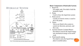
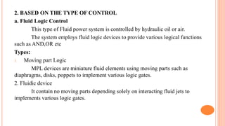
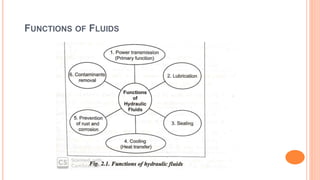
ME8694- HYDRAULICS AND PNEUMATICS
INTRODUCTION TO FLUID POWER – ADVANTAGES AND APPLICATIONS – FLUID POWER SYSTEMS – TYPES OF FLUIDS - PROPERTIES OF FLUIDS AND SELECTION –
BASICS OF HYDRAULICS – PASCAL’S LAW – PRINCIPLES OF FLOW - FRICTION LOSS – WORK, POWER AND TORQUE PROBLEMS, SOURCES OF HYDRAULIC POWER :
PUMPING THEORY – PUMP CLASSIFICATION – CONSTRUCTION, WORKING, DESIGN, ADVANTAGES, DISADVANTAGES, PERFORMANCE, SELECTION CRITERIA OF LINEAR
AND ROTARY – FIXED AND VARIABLE DISPLACEMENT PUMPS – PROBLEMS.
UNIT II HYDRAULIC ACTUATORS AND CONTROL COMPONENTS
HYDRAULIC ACTUATORS: CYLINDERS – TYPES AND CONSTRUCTION, APPLICATION, HYDRAULIC CUSHIONING – HYDRAULIC MOTORS - CONTROL COMPONENTS :
DIRECTION CONTROL, FLOW CONTROL AND PRESSURE CONTROL VALVES – TYPES, CONSTRUCTION AND OPERATION – SERVO AND PROPORTIONAL VALVES –
APPLICATIONS – ACCESSORIES : RESERVOIRS, PRESSURE SWITCHES – APPLICATIONS – FLUID POWER ANSI SYMBOLS – PROBLEMS.
UNIT III HYDRAULIC CIRCUITS AND SYSTEMS
ACCUMULATORS, INTENSIFIERS, INDUSTRIAL HYDRAULIC CIRCUITS – REGENERATIVE, PUMP UNLOADING, DOUBLE- PUMP, PRESSURE INTENSIFIER, AIR-OVER OIL,
SEQUENCE, RECIPROCATION, SYNCHRONIZATION, FAIL-SAFE, SPEED CONTROL, HYDROSTATIC TRANSMISSION, ELECTRO HYDRAULIC CIRCUITS, MECHANICAL
HYDRAULIC SERVO SYSTEMS.
UNIT IV PNEUMATIC AND ELECTRO PNEUMATIC SYSTEMS
PROPERTIES OF AIR – PERFECT GAS LAWS – COMPRESSOR – FILTERS, REGULATOR, LUBRICATOR, MUFFLER, AIR CONTROL VALVES, QUICK EXHAUST VALVES,
PNEUMATIC ACTUATORS, DESIGN OF PNEUMATIC CIRCUIT – CASCADE METHOD – ELECTRO PNEUMATIC SYSTEM – ELEMENTS – LADDER DIAGRAM – PROBLEMS,
INTRODUCTION TO FLUIDICS AND PNEUMATIC LOGIC CIRCUITS.
UNIT V TROUBLE SHOOTING AND APPLICATIONS
INSTALLATION, SELECTION, MAINTENANCE, TROUBLE SHOOTING AND REMEDIES IN HYDRAULIC AND PNEUMATIC SYSTEMS, DESIGN OF HYDRAULIC CIRCUITS FOR
DRILLING, PLANNING, SHAPING, SURFACE GRINDING, PRESS AND FORKLIFT APPLICATIONS. DESIGN OF PNEUMATIC CIRCUITS FOR PICK AND PLACE APPLICATIONS AND
TOOL HANDLING IN CNC MACHINE TOOLS – LOW COST AUTOMATION – HYDRAULIC AND PNEUMATIC POWER PACKS.
TEXT BOOKS:
1. ANTHONY ESPOSITO, “FLUID POWER WITH APPLICATIONS”, PEARSON EDUCATION 2005.
2. MAJUMDAR S.R., “OIL HYDRAULICS SYSTEMS- PRINCIPLES AND MAINTENANCE”, TATA MCGRAW-HILL, 2001.
REFERENCES:
1. ANTHONY LAL, “OIL HYDRAULICS IN THE SERVICE OF INDUSTRY”, ALLIED PUBLISHERS, 1982.
2. DUDELYT, A. PEASE AND JOHN T. PIPPENGER, “BASIC FLUID POWER”, PRENTICE HALL, 1987.
3. MAJUMDAR S.R., “PNEUMATIC SYSTEMS – PRINCIPLES AND MAINTENANCE”, TATA MCGRAW HILL, 1995
4. MICHAEL J, PRINCHES AND ASHBY J. G, “POWER HYDRAULICS”, PRENTICE HALL, 1989.
5. SHANMUGASUNDARAM.K, “HYDRAULIC AND PNEUMATIC CONTROLS”, CHAND & CO, 2006.
UNIT I
FLUID POWER PRINICIPLES AND HYDRAULIC
PUMPS
Introduction to Fluid power:
Fluid power is the technology that deals with the generation, control,
and transmission of power, using pressurized fluids.
Fluid power is called hydraulics when the fluid is a liquid
Fluid power is called pneumatics when the fluid is a gas.
Fluid power system =Hydraulic systems + Pneumatic systems
HISTORY OF FLUID POWER
Ancient historical accounts show that water was used for centuries to
produce power by means of water wheels, and air was used to turn
windmills and propel ships.
Pascal’s law and Bernoulli’s law operate at the very heart of all fluid
power.
Opening the temple’s gate
TYPES OF FLUID SYSTEMS
Fluid transport systems
Fluid transport systems have their sole objective to deliver the fluid from one location
to another to accomplish some useful purpose
Example:
 Pumping stations for pumping water to homes.
 Transport of petroleum oil/gas from one country o another through pipe line.
Fluid power systems
 Fluid power systems are designed specifically to perform work
 These systems use pressurized fluids to produce some useful mechanical movements to
accomplish the desired work.
Example:
Operating fluid cylinder or fluid motor(Earth moving equipment, pneumatic crane)
METHODS OF TRANSMITTING POWER
The three basic methods of transmitting power are:
1. Electrical power transmission
2. Mechanical power transmission
3. Fluid power transmission
1. Hydraulic
2. Pneumatic
BASIC ELEMENTS OF FLUID POWER SYSTEM
ADVANTAGES OF FLUID POWER
1. Ease and accuracy of control
Stopping
Starting
Speed control
Position
2. Multiplication of force
A fluid power system can multiply forces simply and efficiently from a fraction of an ounce to several hundred
tons of output.
3. Constant force or torque
 only fluid power systems are capable of providing constant force or torque regardless of speed changes.
 the highest power-per-weight ratio of any known power source
 Instantly reversible motion
 automatic protection against overloads
 infinitely variable speed control.
ADVANTAGES OF FLUID POWER (CONTI..)
4. Simplicity, Safety and Economy
5. Other Benefits:
High power to weight ratio
Instant reversal of motion with accuracy is possible
Automatic protection against overloads
Infinitely variable controls
Requires less space
Relatively smooth and quiet operation
Greater efficiency
APPLICATIONS OF FLUID POWER
Steering and braking in automobiles
APPLICATIONS OF FLUID POWER
Spacecraft launcher
Applications include landing gear, brakes, flight controls, motor controls and cargo
loading equipment.
Harvests crop
Dental teeth drill
Food industry
Hydraulic Chain Saw
Pneumatic Chain Hoist
DRAWBACKS OF FLUID POWER
 In Hydraulic system, Oil leakage from the hydraulic system into the surroundings.
 Hydraulic pipeline can burst due to excessive oil pressure if proper system design is not
implemented
 In pneumatic systems, components such as compressed air tanks and accumulators
must be properly selected to handle the system maximum air pressure.
level of noise in the vicinity of fluid power systems.
TYPES OF FLUID POWER SYSTEMS
1.Based on control system
A. Open loop system (Pneumatic System)
 It does not use feed back and the performance is based on the characteristics of individual components
of the system.
 It is not accurate as closed loop system but the error can be reduced by careful calibration.
PNEUMATIC SYSTEM
Basic Components of Pneumatic
System:
1. Reservoir
An air tank provided to store the
compressed air
2. Compressor
Used to compress the incoming
atmospheric air
3. Prime mover
Usually an electric motor, is used to
drive the compressor
4. Values
Valves are fitted in the system to
control air direction, pressure, and
flow rate.
5. Actuator
Provided to convert the air energy
into mechanical energy to do useful
work
6. Fluid transfer piping
Provided to carry the compressed air
from one place to another place.
B. Closed loop system (Hydraulic System)
 It uses the feedback
 The output of the system is feedback by a measuring element to a comparator
 Simple closed system uses servo valves and advanced system uses digital electronics.
HYDRAULIC SYSTEM
Basic Components of Hydraulic System:
1. Reservoir
Oil supply tank. Provided o hold the
hydraulic liquid
2. Pump
Used to force the liquid into system
3. Prime mover
Usually an electric motor, is used to
drive the pump
4. Values
Valves are fitted in the system to
control air direction, pressure, and
flow rate.
5. Actuator (Hydro Cylinder/Motor)
Provided to convert the liquid energy
into mechanical energy to do useful
work
6. Fluid transfer piping
Provided to carry the liquid from one
place to another place.
2. BASED ON THE TYPE OF CONTROL
a. Fluid Logic Control
This type of Fluid power system is controlled by hydraulic oil or air.
The system employs fluid logic devices to provide various logical functions
such as AND,OR etc
Types:
1. Moving part Logic
MPL devices are miniature fluid elements using moving parts such as
diaphragms, disks, poppets to implement various logic gates.
2. Fluidic device
It contain no moving parts depending solely on interacting fluid jets to
implements various logic gates.
b. Electrical Control
 This type of system is controlled by electrical device
 They are;
Switches
Relays
Timers
Solenoids
 These devices help to control the starting, sequencing, speed, Positioning, timing
and reversing of actuating cylinders and fluid motors.
c. Electronic control
 It is controlled by microelectronic devices
 The electronic ‘Brain’ is used to control the fluid power ‘muscles’ for doing the
work.
 This system uses the most advanced type of electronic hardware including the
programmable logic controller or microprocessor
FUNCTIONS OF FLUIDS
FUNCTIONS OF FLUIDS
To do the job well a hydraulic fluid must be able to perform at least the
following functions.
1. Transfer fluid power efficiently
2. Lubricate the moving parts
3. Absorb, carry and transfer the heat generated with in the system
4. Be compatible with hydraulic components
5. Remain stable against a wide range of possible physical and chemical
changes, both during storage and while in use.
PROPERTIES OF HYDRAULIC FLUIDS
Density(mass density)
 The density of a fluid is its mass per unit volume:
 Liquids are essentially incompressible.
 Density is highly variable in gases nearly proportional to the pressure.
Specific gravity(relative density)
 Ratio of mass density of fluid to mass density of standard fluid.
Specific volume
Reciprocal of mass density
Viscosity (µ)
 Viscosity is a measure of the fluid’s internal resistance offered to flow.
 Unit is( Ns/m2)
Absolute viscosity
Shear stress required to produce unit rate of shear strain.
Cohesion
Intermolecular attraction between molecules of same liquid
Adhesion
Attraction between molecules of liquid and molecules of solid boundary in contact with
liquid.
Compatibility
Ability of hydraulic fluid to be compatible with the system.
Oxidation stability
 Oxidation is caused by a chemical reaction between the oxygen of the dissolved air
and the oil.
 It creates impurities like sludge, insoluble gum,
and soluble acidic products.
Demulsibility
 The ability of hydraulic fluid to separate from moisture and successfully resist
emulsification.
 The emulsion will promote the destruction of lubricating value and sealant properties.
 Pour point:
◦ The temperature at which an oil will congeal is referred to as the pour point
◦ i.e., the lowest temperature at which the oil is able to flow easily.
 Flash point and Fire point:
◦ Flash point is the temperature at which a liquid gives off vapour in sufficient quantity to
ignite momentarily or flash when flame is applied.
◦ The minimum temperature at which the hydraulic fluid will catch fire and continue burning
is called fire point.
 Neutralization number:
◦ It is a measure of the acidity or alkalinity of the hydraulic fluid.
◦ This is referred to as the pH value of the fluids
◦ High acidity causes the oxidation rate in an oil to increase rapidly.
SATISFACTORY/ REQUIRED QUALITIES OF HYDRAULIC FLUID
 Chemical stability to prevent formation.
 Freedom from acidity ,so that fluid is non corrosive to the metals in the
systems.
 Lubricating properties sufficient to avoid wear.
 Pour point well below the minimum temperature.
 Flash point as high as possible.
 Minimum toxicity.
BASICS OF HYDRAULICS
Pascal’s Law
The principle of fluid power was
developed by Pascal. Pascal’s Law
states that the pressure generated at
any point in a confined fluid acts
equally in all directions.
APPLICATION OF PASCAL'S LAW
1. Hydraulic press
2.HYDRAULIC JACK
3.AIR TO HYDRAULIC PRESSURE BOOSTER
FLUID FLOW
 Laminar flow (Streamline or viscous
flow)
A laminar flow is one which paths
taken by the individual particles do not
cross one another and move along well
defined path.
 Turbulent flow
A turbulent flow is that in a Zig-zag
way.
Causes:
More resistance to flow
Greater energy loss
Increased fluid temperature due to greater
energy loss

Hyraulics and Pneumatics

  • 1.
  • 2.
    INTRODUCTION TO FLUIDPOWER – ADVANTAGES AND APPLICATIONS – FLUID POWER SYSTEMS – TYPES OF FLUIDS - PROPERTIES OF FLUIDS AND SELECTION – BASICS OF HYDRAULICS – PASCAL’S LAW – PRINCIPLES OF FLOW - FRICTION LOSS – WORK, POWER AND TORQUE PROBLEMS, SOURCES OF HYDRAULIC POWER : PUMPING THEORY – PUMP CLASSIFICATION – CONSTRUCTION, WORKING, DESIGN, ADVANTAGES, DISADVANTAGES, PERFORMANCE, SELECTION CRITERIA OF LINEAR AND ROTARY – FIXED AND VARIABLE DISPLACEMENT PUMPS – PROBLEMS. UNIT II HYDRAULIC ACTUATORS AND CONTROL COMPONENTS HYDRAULIC ACTUATORS: CYLINDERS – TYPES AND CONSTRUCTION, APPLICATION, HYDRAULIC CUSHIONING – HYDRAULIC MOTORS - CONTROL COMPONENTS : DIRECTION CONTROL, FLOW CONTROL AND PRESSURE CONTROL VALVES – TYPES, CONSTRUCTION AND OPERATION – SERVO AND PROPORTIONAL VALVES – APPLICATIONS – ACCESSORIES : RESERVOIRS, PRESSURE SWITCHES – APPLICATIONS – FLUID POWER ANSI SYMBOLS – PROBLEMS. UNIT III HYDRAULIC CIRCUITS AND SYSTEMS ACCUMULATORS, INTENSIFIERS, INDUSTRIAL HYDRAULIC CIRCUITS – REGENERATIVE, PUMP UNLOADING, DOUBLE- PUMP, PRESSURE INTENSIFIER, AIR-OVER OIL, SEQUENCE, RECIPROCATION, SYNCHRONIZATION, FAIL-SAFE, SPEED CONTROL, HYDROSTATIC TRANSMISSION, ELECTRO HYDRAULIC CIRCUITS, MECHANICAL HYDRAULIC SERVO SYSTEMS. UNIT IV PNEUMATIC AND ELECTRO PNEUMATIC SYSTEMS PROPERTIES OF AIR – PERFECT GAS LAWS – COMPRESSOR – FILTERS, REGULATOR, LUBRICATOR, MUFFLER, AIR CONTROL VALVES, QUICK EXHAUST VALVES, PNEUMATIC ACTUATORS, DESIGN OF PNEUMATIC CIRCUIT – CASCADE METHOD – ELECTRO PNEUMATIC SYSTEM – ELEMENTS – LADDER DIAGRAM – PROBLEMS, INTRODUCTION TO FLUIDICS AND PNEUMATIC LOGIC CIRCUITS. UNIT V TROUBLE SHOOTING AND APPLICATIONS INSTALLATION, SELECTION, MAINTENANCE, TROUBLE SHOOTING AND REMEDIES IN HYDRAULIC AND PNEUMATIC SYSTEMS, DESIGN OF HYDRAULIC CIRCUITS FOR DRILLING, PLANNING, SHAPING, SURFACE GRINDING, PRESS AND FORKLIFT APPLICATIONS. DESIGN OF PNEUMATIC CIRCUITS FOR PICK AND PLACE APPLICATIONS AND TOOL HANDLING IN CNC MACHINE TOOLS – LOW COST AUTOMATION – HYDRAULIC AND PNEUMATIC POWER PACKS. TEXT BOOKS: 1. ANTHONY ESPOSITO, “FLUID POWER WITH APPLICATIONS”, PEARSON EDUCATION 2005. 2. MAJUMDAR S.R., “OIL HYDRAULICS SYSTEMS- PRINCIPLES AND MAINTENANCE”, TATA MCGRAW-HILL, 2001. REFERENCES: 1. ANTHONY LAL, “OIL HYDRAULICS IN THE SERVICE OF INDUSTRY”, ALLIED PUBLISHERS, 1982. 2. DUDELYT, A. PEASE AND JOHN T. PIPPENGER, “BASIC FLUID POWER”, PRENTICE HALL, 1987. 3. MAJUMDAR S.R., “PNEUMATIC SYSTEMS – PRINCIPLES AND MAINTENANCE”, TATA MCGRAW HILL, 1995 4. MICHAEL J, PRINCHES AND ASHBY J. G, “POWER HYDRAULICS”, PRENTICE HALL, 1989. 5. SHANMUGASUNDARAM.K, “HYDRAULIC AND PNEUMATIC CONTROLS”, CHAND & CO, 2006.
  • 3.
    UNIT I FLUID POWERPRINICIPLES AND HYDRAULIC PUMPS Introduction to Fluid power: Fluid power is the technology that deals with the generation, control, and transmission of power, using pressurized fluids. Fluid power is called hydraulics when the fluid is a liquid Fluid power is called pneumatics when the fluid is a gas. Fluid power system =Hydraulic systems + Pneumatic systems
  • 5.
    HISTORY OF FLUIDPOWER Ancient historical accounts show that water was used for centuries to produce power by means of water wheels, and air was used to turn windmills and propel ships. Pascal’s law and Bernoulli’s law operate at the very heart of all fluid power.
  • 6.
  • 7.
    TYPES OF FLUIDSYSTEMS Fluid transport systems Fluid transport systems have their sole objective to deliver the fluid from one location to another to accomplish some useful purpose Example:  Pumping stations for pumping water to homes.  Transport of petroleum oil/gas from one country o another through pipe line. Fluid power systems  Fluid power systems are designed specifically to perform work  These systems use pressurized fluids to produce some useful mechanical movements to accomplish the desired work. Example: Operating fluid cylinder or fluid motor(Earth moving equipment, pneumatic crane)
  • 8.
    METHODS OF TRANSMITTINGPOWER The three basic methods of transmitting power are: 1. Electrical power transmission 2. Mechanical power transmission 3. Fluid power transmission 1. Hydraulic 2. Pneumatic
  • 12.
    BASIC ELEMENTS OFFLUID POWER SYSTEM
  • 14.
    ADVANTAGES OF FLUIDPOWER 1. Ease and accuracy of control Stopping Starting Speed control Position 2. Multiplication of force A fluid power system can multiply forces simply and efficiently from a fraction of an ounce to several hundred tons of output. 3. Constant force or torque  only fluid power systems are capable of providing constant force or torque regardless of speed changes.  the highest power-per-weight ratio of any known power source  Instantly reversible motion  automatic protection against overloads  infinitely variable speed control.
  • 15.
    ADVANTAGES OF FLUIDPOWER (CONTI..) 4. Simplicity, Safety and Economy 5. Other Benefits: High power to weight ratio Instant reversal of motion with accuracy is possible Automatic protection against overloads Infinitely variable controls Requires less space Relatively smooth and quiet operation Greater efficiency
  • 16.
  • 19.
    Steering and brakingin automobiles APPLICATIONS OF FLUID POWER
  • 20.
    Spacecraft launcher Applications includelanding gear, brakes, flight controls, motor controls and cargo loading equipment.
  • 21.
  • 22.
  • 23.
  • 24.
  • 25.
  • 26.
    DRAWBACKS OF FLUIDPOWER  In Hydraulic system, Oil leakage from the hydraulic system into the surroundings.  Hydraulic pipeline can burst due to excessive oil pressure if proper system design is not implemented  In pneumatic systems, components such as compressed air tanks and accumulators must be properly selected to handle the system maximum air pressure. level of noise in the vicinity of fluid power systems.
  • 27.
    TYPES OF FLUIDPOWER SYSTEMS 1.Based on control system A. Open loop system (Pneumatic System)  It does not use feed back and the performance is based on the characteristics of individual components of the system.  It is not accurate as closed loop system but the error can be reduced by careful calibration.
  • 28.
    PNEUMATIC SYSTEM Basic Componentsof Pneumatic System: 1. Reservoir An air tank provided to store the compressed air 2. Compressor Used to compress the incoming atmospheric air 3. Prime mover Usually an electric motor, is used to drive the compressor 4. Values Valves are fitted in the system to control air direction, pressure, and flow rate. 5. Actuator Provided to convert the air energy into mechanical energy to do useful work 6. Fluid transfer piping Provided to carry the compressed air from one place to another place.
  • 29.
    B. Closed loopsystem (Hydraulic System)  It uses the feedback  The output of the system is feedback by a measuring element to a comparator  Simple closed system uses servo valves and advanced system uses digital electronics.
  • 30.
    HYDRAULIC SYSTEM Basic Componentsof Hydraulic System: 1. Reservoir Oil supply tank. Provided o hold the hydraulic liquid 2. Pump Used to force the liquid into system 3. Prime mover Usually an electric motor, is used to drive the pump 4. Values Valves are fitted in the system to control air direction, pressure, and flow rate. 5. Actuator (Hydro Cylinder/Motor) Provided to convert the liquid energy into mechanical energy to do useful work 6. Fluid transfer piping Provided to carry the liquid from one place to another place.
  • 31.
    2. BASED ONTHE TYPE OF CONTROL a. Fluid Logic Control This type of Fluid power system is controlled by hydraulic oil or air. The system employs fluid logic devices to provide various logical functions such as AND,OR etc Types: 1. Moving part Logic MPL devices are miniature fluid elements using moving parts such as diaphragms, disks, poppets to implement various logic gates. 2. Fluidic device It contain no moving parts depending solely on interacting fluid jets to implements various logic gates.
  • 32.
    b. Electrical Control This type of system is controlled by electrical device  They are; Switches Relays Timers Solenoids  These devices help to control the starting, sequencing, speed, Positioning, timing and reversing of actuating cylinders and fluid motors. c. Electronic control  It is controlled by microelectronic devices  The electronic ‘Brain’ is used to control the fluid power ‘muscles’ for doing the work.  This system uses the most advanced type of electronic hardware including the programmable logic controller or microprocessor
  • 33.
  • 34.
    FUNCTIONS OF FLUIDS Todo the job well a hydraulic fluid must be able to perform at least the following functions. 1. Transfer fluid power efficiently 2. Lubricate the moving parts 3. Absorb, carry and transfer the heat generated with in the system 4. Be compatible with hydraulic components 5. Remain stable against a wide range of possible physical and chemical changes, both during storage and while in use.
  • 35.
    PROPERTIES OF HYDRAULICFLUIDS Density(mass density)  The density of a fluid is its mass per unit volume:  Liquids are essentially incompressible.  Density is highly variable in gases nearly proportional to the pressure. Specific gravity(relative density)  Ratio of mass density of fluid to mass density of standard fluid. Specific volume Reciprocal of mass density
  • 36.
    Viscosity (µ)  Viscosityis a measure of the fluid’s internal resistance offered to flow.  Unit is( Ns/m2) Absolute viscosity Shear stress required to produce unit rate of shear strain. Cohesion Intermolecular attraction between molecules of same liquid Adhesion Attraction between molecules of liquid and molecules of solid boundary in contact with liquid.
  • 37.
    Compatibility Ability of hydraulicfluid to be compatible with the system. Oxidation stability  Oxidation is caused by a chemical reaction between the oxygen of the dissolved air and the oil.  It creates impurities like sludge, insoluble gum, and soluble acidic products. Demulsibility  The ability of hydraulic fluid to separate from moisture and successfully resist emulsification.  The emulsion will promote the destruction of lubricating value and sealant properties.
  • 38.
     Pour point: ◦The temperature at which an oil will congeal is referred to as the pour point ◦ i.e., the lowest temperature at which the oil is able to flow easily.  Flash point and Fire point: ◦ Flash point is the temperature at which a liquid gives off vapour in sufficient quantity to ignite momentarily or flash when flame is applied. ◦ The minimum temperature at which the hydraulic fluid will catch fire and continue burning is called fire point.  Neutralization number: ◦ It is a measure of the acidity or alkalinity of the hydraulic fluid. ◦ This is referred to as the pH value of the fluids ◦ High acidity causes the oxidation rate in an oil to increase rapidly.
  • 39.
    SATISFACTORY/ REQUIRED QUALITIESOF HYDRAULIC FLUID  Chemical stability to prevent formation.  Freedom from acidity ,so that fluid is non corrosive to the metals in the systems.  Lubricating properties sufficient to avoid wear.  Pour point well below the minimum temperature.  Flash point as high as possible.  Minimum toxicity.
  • 40.
    BASICS OF HYDRAULICS Pascal’sLaw The principle of fluid power was developed by Pascal. Pascal’s Law states that the pressure generated at any point in a confined fluid acts equally in all directions.
  • 41.
    APPLICATION OF PASCAL'SLAW 1. Hydraulic press
  • 42.
  • 43.
    3.AIR TO HYDRAULICPRESSURE BOOSTER
  • 44.
    FLUID FLOW  Laminarflow (Streamline or viscous flow) A laminar flow is one which paths taken by the individual particles do not cross one another and move along well defined path.  Turbulent flow A turbulent flow is that in a Zig-zag way. Causes: More resistance to flow Greater energy loss Increased fluid temperature due to greater energy loss