1. The document discusses various image transforms including discrete cosine transform (DCT), discrete wavelet transform (DWT), and contourlet transform.
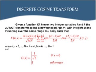
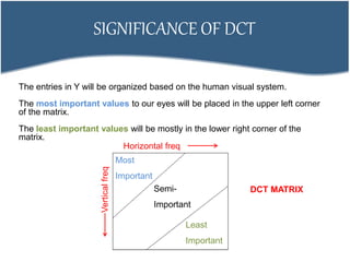
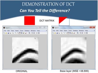
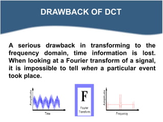
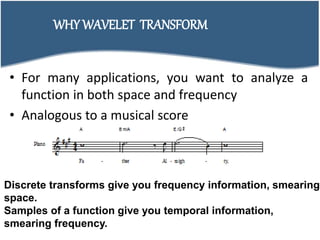
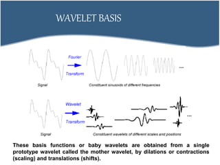
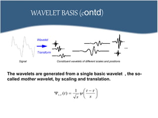
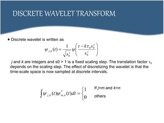
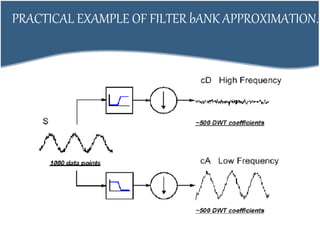
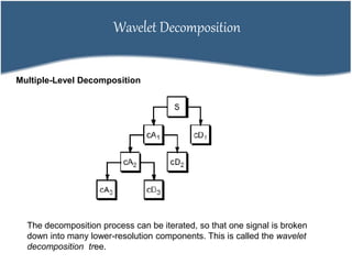
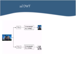
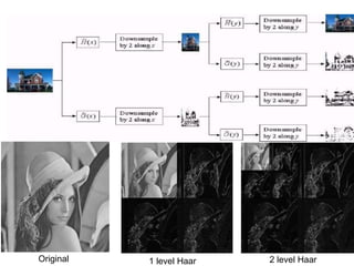
2. DCT transforms an image into frequency domain and organizes values based on human visual system importance. DWT analyzes images using wavelets of different scales and positions.
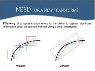
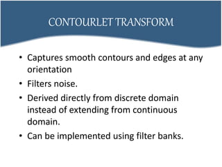
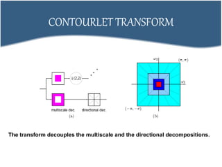
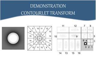
3. Contourlet transform is derived directly from discrete domain to capture smooth contours and edges at any orientation, decoupling multiscale and directional decompositions. It provides better efficiency than DWT for representing images.