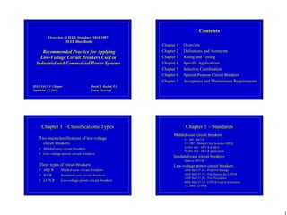
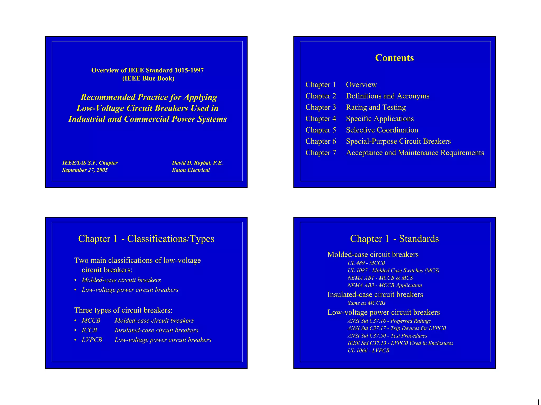
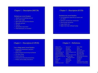
1
Overview of IEEE Standard 1015-1997
(IEEE Blue Book)
Recommended Practice for Applying
Low-Voltage Circuit Breakers Used in
Industrial and Commercial Power Systems
David D. Roybal, P.E.
Eaton Electrical
IEEE/IAS S.F. Chapter
September 27, 2005
Contents
Chapter 1 Overview
Chapter 2 Definitions and Acronyms
Chapter 3 Rating and Testing
Chapter 4 Specific Applications
Chapter 5 Selective Coordination
Chapter 6 Special-Purpose Circuit Breakers
Chapter 7 Acceptance and Maintenance Requirements
Chapter 1 - Classifications/Types
Two main classifications of low-voltage
circuit breakers:
• Molded-case circuit breakers
• Low-voltage power circuit breakers
Three types of circuit breakers:
• MCCB Molded-case circuit breakers
• ICCB Insulated-case circuit breakers
• LVPCB Low-voltage power circuit breakers
Chapter 1 - Standards
Molded-case circuit breakers
UL 489 - MCCB
UL 1087 - Molded Case Switches (MCS)
NEMA AB1 - MCCB & MCS
NEMA AB3 - MCCB Application
Insulated-case circuit breakers
Same as MCCBs
Low-voltage power circuit breakers
ANSI Std C37.16 - Preferred Ratings
ANSI Std C37.17 - Trip Devices for LVPCB
ANSI Std C37.50 - Test Procedures
IEEE Std C37.13 - LVPCB Used in Enclosures
UL 1066 - LVPCB
2
Chapter 1 - Description (MCCB)
Molded-case circuit breakers
• Molded case of insulating material
• Over-center toggle
• Quick-make-quick-break mechanism
• Manually operated
• Trip free
• Intermediate trip position
• Field maintenance not intended
Chapter 1 - Description (ICCB)
Insulated-case circuit breakers
• Case designed for inspection of contacts and
arc chutes
• Stationary and drawout construction
• Stored energy mechanism
• Larger frame sizes
• Higher short-time withstand ratings
Chapter 1 - Description (LVPCB)
Low-voltage power circuit breakers
• Designed for maintenance and parts
replacement
• Spring charged stored-energy mechanism
• Two-step closing
• Fixed or drawout
• Connected-test-disconnected positions
• Primary and secondary disconnects
Chapter 2 – Definitions
Alarm switch
Auxiliary switch
Circuit breaker
Coordination
Current-limiting CB
Drawout-mounted
Dynamic impedance
Instantaneous-trip-only
ICCB
Inverse time
LVPCB
MCCB
Molded-case switch
Overcurrent
Overload
Panelboard
Peak current
Peak let-through current
Pickup
Prospective fault current
Rated short-time
withstand current
Rating plug
RMS sensing
Selectivity
Sensor
Series rating
Setting
Short-circuit
Short-time current
Short-time delay
Short-time rating
Shunt trip device
Stored-energy mechanism
Switchboard
Switchgear
Tripping
Transient recovery voltage
Zone selective interlocking
3
Chapter 2 –Acronyms
Markings designating circuit breaker ratings:
• 40C – Acceptable for use in ambient temperature up to 40°C
• AIR – Amperes interrupting rating
• CTL – Class CTL circuit breaker prevents more circuit breaker poles
from being installed than the number intended
• HACR – Heating, Air Conditioning, and Refrigeration. Designates
compliance with NEC for group motor installations.
• HID – High Intensity Discharge. Indicates construction suitable for
switching HID lighting loads.
• SWD – Switching Duty. Designates compliance with requirements for
circuit breakers used as switches in fluorescent lighting circuits.
Chapter 3 - Rating and Testing
Selection criteria:
• To carry the required full-load current without overheating
• To switch and isolate or disconnect the load from the source
at the given system voltage
• To interrupt any possible abnormally high operating current
or short-circuit current likely to be encountered during
operation
• To be able to perform these functions over an acceptably
long period of time under the operating and environmental
conditions that will actually prevail in the application
The role of standards
Chapter 3 - MCCB
Molded-case circuit breakers
• Tested and rated according to UL 489
• Completely contained within a molded case of
insulating material
• 15A – 6000A with various interrupting ratings
• Fast interruption short-circuit elements
• With electronic trip units can have limited short-
delay and ground fault sensing capability
• Interrupt fast enough to limit the prospective fault-
current let-through
• Some are identified as current limiting
• Not designed to be field maintainable
Chapter 3 - ICCB
Insulated-case circuit breakers
• Tested and rated according to UL 489
• Larger frame sizes
• Fast in interruption
• Can have electronic trip units with short-time ratings
and ground-fault current sensing
• Utilize stored-energy operating mechanisms
• Partially field maintainable
4
Chapter 3 - LVPCB
Low voltage power circuit breakers
• Tested and rated according to ANSI C37 standards
• Used primarily in drawout switchgear
• Short-time ratings
• Designed to be maintainable in the field
Chapter 3 - Endurance
Minimum
Number of Operating Cycles
Frame
Size
Operation
Rate
(cycles/hour)
Between
Servicing
With
Current
Without
Current
Total
UL489 ANSI
C37.50
†
UL489* ANSI
C37.50
†
UL489 ANSI
C37.50
†
UL489 ANSI
C37.50
†
UL489 ANSI
C37.50
†
225
300 30 - 2500 4000 4000 4000 10000 8000 14000
400
240 - - - 1000 - 5000 - 6000 -
600
240 30 - 1750 1000 2800 5000 9700 6000 12500
800
60 30 - 1750 500 2800 3000 9700 3500 12500
1200
60 - - - 500 - 2000 - 2500 -
1600
60 30 - 500 500 800 2000 3200 2500 4000
2000
60 30 - 500 500 800 2000 3200 2500 4000
2500
60 - - - 500 - 2000 - 2500 -
3000
60 30 - 250 400 400 1100 1100 1500 1500
4000
60 30 - 250 400 400 1100 1100 1500 1500
Chapter 3 - MCCB/ICCB Interrupting Ability
Test
Number*
Tested In
Sequence
Duty
Cycle
Number
of
Maximum
Rated
Actual Test Current (rms symmetrical kA)
(Table 7.1.7.2)
Number Poles Voltage
Frame Rating (amperes)
(Table
7.1.1.2)
(Table
7.1.7.1)
(Table
7.1.7.1)
(Table
7.1.7.1)
225 600 800 1200 1600 2000 2500 3000 4000
2 Z O-CO 1 600 8.6 8.6 8.6 12.1 14 14 20 25 30
3 Z O-CO 1 600 8.6 8.6 8.6 12.1 14 14 20 25 30
4 Z O-CO 1 600 8.6 8.6 8.6 12.1 14 14 20 25 30
6 Z O 3 600 10 10 10 14 – – – – –
7 Z O 3 600 – – – – 20 25 30 35 45
9 Y O-CO 3 600 3 6 10 14 20 25 30 35 45
Test
Number†
Duty
Cycle
Number of
Poles
Trip
Rating
Actual Test Current
(Tables 7.1.11.1.1 and 8.1)
A O-CO 3 Maximum Same as maximum interrupting capacity rating
B O-CO 3 Maximum I/C rating at maximum voltage rating
C O-CO 3 Maximum I/C at maximum kVA rating
D O-CO 3 Minimum Maximum I/C rating
* Tests 1 through 9 are standard interrupting capacity tests.
†
Tests A through D are high interrupting capacity tests.
Chapter 3 - LVPCB Interrupting Ability
Test
Number
Tested In
Sequence
Duty
Cycle
Number of
Poles
Maximum
Rated
Actual Test Current (rms symmetrical kA)
Number Voltage
Frame Rating (amperes)
225 600 800 1600 2000 3000 3200 4000
1 I O-CO 3 635 14 22 22 42 42 65 65 85
2 II O-CO 3 508 22 30 30 50 50 65 65 85
3 II O-CO 3 254 25 42 42 65 65 85 85 130
4 II O-CO 1 635 12.2 19.1 19.1 36.5 36.5 56.6 56.6 74
5 II O-CO 1 508 19.1 26.1 26.1 43.5 43.5 56.6 56.6 74
6 II O-CO 1 254 21.8 36.5 36.5 56.6 56.6 74 74 113.1
7 III O 3 635 14 22 22 42 42 65 65 85
8 IV O-CO 3 635 14 22 22 42 42 65 65 85
†
ANSI C37.50-1989 and ANSI C37.16-1988
5
Chapter 3 - Voltage Rating Considerations
MCCB/ICCB/LVPCB Circuit breakers
• Nominal system voltages of 600V, 480V, and 240V
• MCCB/ICCB also 120V, 120/240V, 277V, 347V,
480Y/277V, and 600Y/347V
• MCCB/ICCB – nominal voltage levels are maximum
“not to exceed” voltages
• LVPCB – assigned maximum voltages of 254V, 508V,
and 635V
• Slash marks
• Insulation testing - 2200V ac dielectric withstand
voltage test (or equivalent dc) when new
Chapter 3 - Frequency and Temperature
Frequency
• Rated for 60 Hz operation
• Other frequency capabilities are marked
• May have to be de-rated
Temperature
• MCCB/ICCB: -5°C to +40°C
• LVPCB: -5°C to +40°C, but IEEE C37.20.1 permits
temperature surrounding switchgear to be -30°C to
+40°C
Chapter 3 - Enclosures and Conductors
Enclosures
• Fully rated for operation in free air
• LVPCBs are applied in enclosures and fully rated
• Some MCCBs are also 100% rated. They have a
minimum enclosure size. Use 90°C conductors.
• MCCBs in enclosures 80% rated for continuous loads
Cable, wire, and conductor considerations
• Conductors serve as heat sinks – 75°C wire required
• Higher temperature wire must be used at the 75°C
ampacity
• Welding cable should not be used
• 125A or less – marked for 60°C, 75°C , 60°/75°C
Chapter 3 - Ambient, Humidity, Altitude
Ambient
• Should be de-rated in ambients above maximum
• Consult the manufacturer for de-rating information
Altitude
• Reduced insulation and heat transfer properties of less
dense air require de-rating of voltage withstand and
current carrying capacity
• MCCB/ICCB – De-rated above 6000 feet. Consult the
manufacturer.
• LVPCB – De-rated above 6600 feet
• IEEE C37.13: 8500 feet, .99 current and .95 voltage
• IEEE C37.13: 13000 feet, .96 current and .80 voltage
6
Chapter 3 - Other Considerations
• National Electrical Code
• Preferred current ratings
• Effect of non-linear loads
• High inrush loads
• Overload testing
• Safety factor for current loading
• Forced-air cooling of LVPCBs
• Short-circuit interrupting rating
• Fault current calculations
• Circuit breaker interrupting ratings
• Single-pole fault interruption testing
Chapter 3 - Other Considerations
• Testing
• Blow-open contact arms
• Circuit breaker useful life
• Interrupting duty and maintenance
• Integrally fused devices
• Series-connected rating
• Cascade arrangement
• Short-time rating
• X/R ratio – short-circuit power factor
• Power system design considerations
Chapter 3 - X/R Ratio
(Short-Circuit Power Factor)
Type of
Circuit Breaker
Interrupting
Rating (kA)
Power
Factor
Test Range
X/R Test
Range
Molded Case 10 or less 0.45 – 0.50 1.98 - 1.73
Molded Case over 10 to 20 0.25 – 0.30 3.87 - 3.18
Molded Case over 20 0.15 – 0.20 6.6 - 4.9
Low-Voltage Power all 0.15 max. 6.6 min.
Chapter 3 - Multiplying Factors
20 4.8990 0.762 0.899 1.000 1.000
15 6.5912 0.718 0.847 0.942 1.000
12 8.2731 0.691 0.815 0.907 0.962
10 9.9499 0.673 0.794 0.883 0.937
9 11.7221 0.659 0.778 0.865 0.918
7 14.2507 0.645 0.761 0.847 0.899
5 19.9750 0.627 0.740 0.823 0.874
% P.F. X/R Interrupting Rating
≤ 10 kA > 10 kA
≤ 20 kA
> 20 kA All
LV PCB
7
Chapter 3 - Overload Performance
Frame Size
(amps)
Minimum Operation Rate
(cycles/hour)
Number of Operating Cycles
UL489 ANSI C37.50* UL489 ANSI C37.50*
225 300 60 50 50
400 240 - 50 -
600 240 60 50 50
800 60 60 50 50
1200 60 - 50 -
1600 60 60 50 38
2000 60 60 25 38
2500 60 - 25 -
3000 60 N/A 28 N/A
4000 60 N/A 28 N/A
Chapter 4 - Selection Considerations
• System Voltage
• System Grounding
• System Frequency
• Continuous Current Rating
• Ambient Temperature and Altitude
• Harmonics
• Interrupting Rating
• Series Connected Rating
• Fully-Rated Versus Series-Connected Rated
• Arcing Ground Fault Protection
Chapter 4 - Modifications and Accessories
• Shunt trip device
• Undervoltage release
• Auxiliary switches
• Mechanism operated cell (MOC) switch
• Truck operated cell (TOC) switch
• Alarm switches
• Motor operators on MCCBs
• Electrical close mechanism on LVPCBs and ICCBs
• Mechanical interlocks
• Moisture, Fungus, and corrosion treatment
• Terminal shields
• Handle locks and handle ties
• Shutters
Chapter 4 - Specific Applications
Normal Environmental and Operating Conditions
• Ambient temperature between 0°C and 40°C
• Altitude does not exceed 6600 ft (2000 m)
• Seismic zone 0
• Frequency of 60 Hz
8
Chapter 4 - Specific Applications
Abnormal Environmental and Operating Conditions
• Operation at ambient temperatures below 0°C or above 40°C
• Operation at altitudes above 6600 ft (2000 m)
• Exposure to corrosive materials
• Exposure to explosive fumes or dust
• Exposure to dust or moisture
• Seismic zones 1, 2, 3, or 4
• Abnormal vibrations
• Unusual operating duties
• Harmonics
• Repetitive duty cycle
• Capacitor bank switching
• Frequent switching
• Circuits with high X/R ratios
• Single pole interruption with three-pole breakers
• Frequencies other than 60 Hz
• Occurrence of frequent and/or severe faults
Chapter 4 - Comparison of Features
LVPCB ICCB MCCB
Selective trip over full range of
fault currents up to interrupting
rating.
Selective trip over partial range of
fault currents within interrupting
rating.
Selective trip over a smaller range
of fault currents within interrupting
rating.
Types of operators: mechanically
operated, two-step, stored energy,
and electrical two-step stored
energy.
Types of operators: mechanically
operated, two-step, stored energy,
and electrical two-step stored
energy.
Types of operators: mechanically
operated over-center toggle or
motor operator.
Available in draw-out construction
permitting racking to a distinct
“test position” and removal for
maintenance.
Available in draw-out construction
permitting racking to a distinct
“test position” and removal for
maintenance.
Some are available in plug-in
design allowing removal for
inspection and maintenance.
Large frame sizes may be available
in draw-out construction.
Operation counter is available. Operation counter is available. Operation counter is available.
Interrupting duty at 480 Vac:
22-100 kA without fuses and up to
200 kA with fuses.
Interrupting duty at 480 Vac:
22-100 kA
Interrupting duty at 480 Vac:
22-65 kA without fuses and up to
200 kA with integral fuses or for
current-limiting type.
Chapter 4 - Comparison of Features
LVPCB ICCB MCCB
Current limiting available only with
fuses.
Current limiting not available. Current limiting available with and
without fuses.
Usually most costly. Usually mid-range cost, but
depends on the enclosure selected.
Usually least costly.
Small number of frame sizes
available.
Small number of frame sizes
available.
Large number of frame sizes
available.
Extensive maintenance possible on
all frame sizes.
Limited maintenance possible on
larger frame sizes.
Limited maintenance possible on
larger frame sizes.
Used in enclosures, switchboards,
and switchgear.
Used in enclosures, switchboards,
and switchgear.
Used in enclosures, panelboards,
and switchboards.
Not available in series ratings. Not available in series ratings. Available in series ratings.
100% continuous current rated in its
enclosure
80% continuous-current rated,
unless specifically stated to be rated
100% in an enclosure.
80% continuous-current rated,
unless specifically stated to be rated
100% in an enclosure.
IEEE Standard C37.13 UL 489 UL 489
Chapter 4 - Service Requirements
and Protection
Main circuit breakers
• Disconnecting means
• Overload, short-circuit, and GF protection
• General application considerations
Tie circuit breakers
• Disconnecting means
• Overload, short-circuit, and GF protection
• General application considerations
9
Chapter 4 - Service Requirements
and Protection
Feeder protection
• Overload protection of cables
• Short-circuit and GF protection
• Protection of busway
• Protection of switchgear bus
• Protection of switchboard bus
• Protection of motor feeders and motors
• Feeder and branch-circuit protection
• Protection of generators
• Protection of capacitors
• Protection of transformers
Chapter 5 - Selective Coordination
LVPCBs
• Electromechanical trip devices
• Electronic trip devices
• Long-time delay protection
• Short-time delay protection
• Instantaneous protection
• Ground-fault protection
MCCBs and ICCBs
• Thermal-magnetic circuit breakers
• Electronic trip devices
• Long-time and short-time delay protection
• Instantaneous protection
• Ground-fault protection
Chapter 5 - Selective Coordination Chapter 5 - Selective Coordination
10
Chapter 5 - Other Coordinating Devices
Low-voltage fuses
Medium-voltage fuses
Overcurrent relays
Coordination Examples
Chapter 6 - Special-Purpose Circuit Breakers
Instantaneous-trip circuit breakers (MCPs)
• Ratings
• Current-limiting attachments
• Code considerations
• Setting of instantaneous-trip breakers
• Energy-efficient motors
Mine-duty circuit breakers
Current-limiting circuit breakers
Molded-case switches
Integrally fused circuit breakers
Chapter 7 - Acceptance and Maintenance
Maintenance program
Maintenance of MCCBs
Maintenance of LVPCBs
Documenting maintenance results
Testing program
Failures detected
Overview of IEEE Standard 1015-1997
(IEEE Blue Book)
Recommended Practice for Applying
Low-Voltage Circuit Breakers Used in
Industrial and Commercial Power Systems
David D. Roybal, P.E.
Eaton Electrical
IEEE/IAS S.F. Chapter
September 27, 2005

IEEE Blue Book

  • 1.
    1 Overview of IEEEStandard 1015-1997 (IEEE Blue Book) Recommended Practice for Applying Low-Voltage Circuit Breakers Used in Industrial and Commercial Power Systems David D. Roybal, P.E. Eaton Electrical IEEE/IAS S.F. Chapter September 27, 2005 Contents Chapter 1 Overview Chapter 2 Definitions and Acronyms Chapter 3 Rating and Testing Chapter 4 Specific Applications Chapter 5 Selective Coordination Chapter 6 Special-Purpose Circuit Breakers Chapter 7 Acceptance and Maintenance Requirements Chapter 1 - Classifications/Types Two main classifications of low-voltage circuit breakers: • Molded-case circuit breakers • Low-voltage power circuit breakers Three types of circuit breakers: • MCCB Molded-case circuit breakers • ICCB Insulated-case circuit breakers • LVPCB Low-voltage power circuit breakers Chapter 1 - Standards Molded-case circuit breakers UL 489 - MCCB UL 1087 - Molded Case Switches (MCS) NEMA AB1 - MCCB & MCS NEMA AB3 - MCCB Application Insulated-case circuit breakers Same as MCCBs Low-voltage power circuit breakers ANSI Std C37.16 - Preferred Ratings ANSI Std C37.17 - Trip Devices for LVPCB ANSI Std C37.50 - Test Procedures IEEE Std C37.13 - LVPCB Used in Enclosures UL 1066 - LVPCB
  • 2.
    2 Chapter 1 -Description (MCCB) Molded-case circuit breakers • Molded case of insulating material • Over-center toggle • Quick-make-quick-break mechanism • Manually operated • Trip free • Intermediate trip position • Field maintenance not intended Chapter 1 - Description (ICCB) Insulated-case circuit breakers • Case designed for inspection of contacts and arc chutes • Stationary and drawout construction • Stored energy mechanism • Larger frame sizes • Higher short-time withstand ratings Chapter 1 - Description (LVPCB) Low-voltage power circuit breakers • Designed for maintenance and parts replacement • Spring charged stored-energy mechanism • Two-step closing • Fixed or drawout • Connected-test-disconnected positions • Primary and secondary disconnects Chapter 2 – Definitions Alarm switch Auxiliary switch Circuit breaker Coordination Current-limiting CB Drawout-mounted Dynamic impedance Instantaneous-trip-only ICCB Inverse time LVPCB MCCB Molded-case switch Overcurrent Overload Panelboard Peak current Peak let-through current Pickup Prospective fault current Rated short-time withstand current Rating plug RMS sensing Selectivity Sensor Series rating Setting Short-circuit Short-time current Short-time delay Short-time rating Shunt trip device Stored-energy mechanism Switchboard Switchgear Tripping Transient recovery voltage Zone selective interlocking
  • 3.
    3 Chapter 2 –Acronyms Markingsdesignating circuit breaker ratings: • 40C – Acceptable for use in ambient temperature up to 40°C • AIR – Amperes interrupting rating • CTL – Class CTL circuit breaker prevents more circuit breaker poles from being installed than the number intended • HACR – Heating, Air Conditioning, and Refrigeration. Designates compliance with NEC for group motor installations. • HID – High Intensity Discharge. Indicates construction suitable for switching HID lighting loads. • SWD – Switching Duty. Designates compliance with requirements for circuit breakers used as switches in fluorescent lighting circuits. Chapter 3 - Rating and Testing Selection criteria: • To carry the required full-load current without overheating • To switch and isolate or disconnect the load from the source at the given system voltage • To interrupt any possible abnormally high operating current or short-circuit current likely to be encountered during operation • To be able to perform these functions over an acceptably long period of time under the operating and environmental conditions that will actually prevail in the application The role of standards Chapter 3 - MCCB Molded-case circuit breakers • Tested and rated according to UL 489 • Completely contained within a molded case of insulating material • 15A – 6000A with various interrupting ratings • Fast interruption short-circuit elements • With electronic trip units can have limited short- delay and ground fault sensing capability • Interrupt fast enough to limit the prospective fault- current let-through • Some are identified as current limiting • Not designed to be field maintainable Chapter 3 - ICCB Insulated-case circuit breakers • Tested and rated according to UL 489 • Larger frame sizes • Fast in interruption • Can have electronic trip units with short-time ratings and ground-fault current sensing • Utilize stored-energy operating mechanisms • Partially field maintainable
  • 4.
    4 Chapter 3 -LVPCB Low voltage power circuit breakers • Tested and rated according to ANSI C37 standards • Used primarily in drawout switchgear • Short-time ratings • Designed to be maintainable in the field Chapter 3 - Endurance Minimum Number of Operating Cycles Frame Size Operation Rate (cycles/hour) Between Servicing With Current Without Current Total UL489 ANSI C37.50 † UL489* ANSI C37.50 † UL489 ANSI C37.50 † UL489 ANSI C37.50 † UL489 ANSI C37.50 † 225 300 30 - 2500 4000 4000 4000 10000 8000 14000 400 240 - - - 1000 - 5000 - 6000 - 600 240 30 - 1750 1000 2800 5000 9700 6000 12500 800 60 30 - 1750 500 2800 3000 9700 3500 12500 1200 60 - - - 500 - 2000 - 2500 - 1600 60 30 - 500 500 800 2000 3200 2500 4000 2000 60 30 - 500 500 800 2000 3200 2500 4000 2500 60 - - - 500 - 2000 - 2500 - 3000 60 30 - 250 400 400 1100 1100 1500 1500 4000 60 30 - 250 400 400 1100 1100 1500 1500 Chapter 3 - MCCB/ICCB Interrupting Ability Test Number* Tested In Sequence Duty Cycle Number of Maximum Rated Actual Test Current (rms symmetrical kA) (Table 7.1.7.2) Number Poles Voltage Frame Rating (amperes) (Table 7.1.1.2) (Table 7.1.7.1) (Table 7.1.7.1) (Table 7.1.7.1) 225 600 800 1200 1600 2000 2500 3000 4000 2 Z O-CO 1 600 8.6 8.6 8.6 12.1 14 14 20 25 30 3 Z O-CO 1 600 8.6 8.6 8.6 12.1 14 14 20 25 30 4 Z O-CO 1 600 8.6 8.6 8.6 12.1 14 14 20 25 30 6 Z O 3 600 10 10 10 14 – – – – – 7 Z O 3 600 – – – – 20 25 30 35 45 9 Y O-CO 3 600 3 6 10 14 20 25 30 35 45 Test Number† Duty Cycle Number of Poles Trip Rating Actual Test Current (Tables 7.1.11.1.1 and 8.1) A O-CO 3 Maximum Same as maximum interrupting capacity rating B O-CO 3 Maximum I/C rating at maximum voltage rating C O-CO 3 Maximum I/C at maximum kVA rating D O-CO 3 Minimum Maximum I/C rating * Tests 1 through 9 are standard interrupting capacity tests. † Tests A through D are high interrupting capacity tests. Chapter 3 - LVPCB Interrupting Ability Test Number Tested In Sequence Duty Cycle Number of Poles Maximum Rated Actual Test Current (rms symmetrical kA) Number Voltage Frame Rating (amperes) 225 600 800 1600 2000 3000 3200 4000 1 I O-CO 3 635 14 22 22 42 42 65 65 85 2 II O-CO 3 508 22 30 30 50 50 65 65 85 3 II O-CO 3 254 25 42 42 65 65 85 85 130 4 II O-CO 1 635 12.2 19.1 19.1 36.5 36.5 56.6 56.6 74 5 II O-CO 1 508 19.1 26.1 26.1 43.5 43.5 56.6 56.6 74 6 II O-CO 1 254 21.8 36.5 36.5 56.6 56.6 74 74 113.1 7 III O 3 635 14 22 22 42 42 65 65 85 8 IV O-CO 3 635 14 22 22 42 42 65 65 85 † ANSI C37.50-1989 and ANSI C37.16-1988
  • 5.
    5 Chapter 3 -Voltage Rating Considerations MCCB/ICCB/LVPCB Circuit breakers • Nominal system voltages of 600V, 480V, and 240V • MCCB/ICCB also 120V, 120/240V, 277V, 347V, 480Y/277V, and 600Y/347V • MCCB/ICCB – nominal voltage levels are maximum “not to exceed” voltages • LVPCB – assigned maximum voltages of 254V, 508V, and 635V • Slash marks • Insulation testing - 2200V ac dielectric withstand voltage test (or equivalent dc) when new Chapter 3 - Frequency and Temperature Frequency • Rated for 60 Hz operation • Other frequency capabilities are marked • May have to be de-rated Temperature • MCCB/ICCB: -5°C to +40°C • LVPCB: -5°C to +40°C, but IEEE C37.20.1 permits temperature surrounding switchgear to be -30°C to +40°C Chapter 3 - Enclosures and Conductors Enclosures • Fully rated for operation in free air • LVPCBs are applied in enclosures and fully rated • Some MCCBs are also 100% rated. They have a minimum enclosure size. Use 90°C conductors. • MCCBs in enclosures 80% rated for continuous loads Cable, wire, and conductor considerations • Conductors serve as heat sinks – 75°C wire required • Higher temperature wire must be used at the 75°C ampacity • Welding cable should not be used • 125A or less – marked for 60°C, 75°C , 60°/75°C Chapter 3 - Ambient, Humidity, Altitude Ambient • Should be de-rated in ambients above maximum • Consult the manufacturer for de-rating information Altitude • Reduced insulation and heat transfer properties of less dense air require de-rating of voltage withstand and current carrying capacity • MCCB/ICCB – De-rated above 6000 feet. Consult the manufacturer. • LVPCB – De-rated above 6600 feet • IEEE C37.13: 8500 feet, .99 current and .95 voltage • IEEE C37.13: 13000 feet, .96 current and .80 voltage
  • 6.
    6 Chapter 3 -Other Considerations • National Electrical Code • Preferred current ratings • Effect of non-linear loads • High inrush loads • Overload testing • Safety factor for current loading • Forced-air cooling of LVPCBs • Short-circuit interrupting rating • Fault current calculations • Circuit breaker interrupting ratings • Single-pole fault interruption testing Chapter 3 - Other Considerations • Testing • Blow-open contact arms • Circuit breaker useful life • Interrupting duty and maintenance • Integrally fused devices • Series-connected rating • Cascade arrangement • Short-time rating • X/R ratio – short-circuit power factor • Power system design considerations Chapter 3 - X/R Ratio (Short-Circuit Power Factor) Type of Circuit Breaker Interrupting Rating (kA) Power Factor Test Range X/R Test Range Molded Case 10 or less 0.45 – 0.50 1.98 - 1.73 Molded Case over 10 to 20 0.25 – 0.30 3.87 - 3.18 Molded Case over 20 0.15 – 0.20 6.6 - 4.9 Low-Voltage Power all 0.15 max. 6.6 min. Chapter 3 - Multiplying Factors 20 4.8990 0.762 0.899 1.000 1.000 15 6.5912 0.718 0.847 0.942 1.000 12 8.2731 0.691 0.815 0.907 0.962 10 9.9499 0.673 0.794 0.883 0.937 9 11.7221 0.659 0.778 0.865 0.918 7 14.2507 0.645 0.761 0.847 0.899 5 19.9750 0.627 0.740 0.823 0.874 % P.F. X/R Interrupting Rating ≤ 10 kA > 10 kA ≤ 20 kA > 20 kA All LV PCB
  • 7.
    7 Chapter 3 -Overload Performance Frame Size (amps) Minimum Operation Rate (cycles/hour) Number of Operating Cycles UL489 ANSI C37.50* UL489 ANSI C37.50* 225 300 60 50 50 400 240 - 50 - 600 240 60 50 50 800 60 60 50 50 1200 60 - 50 - 1600 60 60 50 38 2000 60 60 25 38 2500 60 - 25 - 3000 60 N/A 28 N/A 4000 60 N/A 28 N/A Chapter 4 - Selection Considerations • System Voltage • System Grounding • System Frequency • Continuous Current Rating • Ambient Temperature and Altitude • Harmonics • Interrupting Rating • Series Connected Rating • Fully-Rated Versus Series-Connected Rated • Arcing Ground Fault Protection Chapter 4 - Modifications and Accessories • Shunt trip device • Undervoltage release • Auxiliary switches • Mechanism operated cell (MOC) switch • Truck operated cell (TOC) switch • Alarm switches • Motor operators on MCCBs • Electrical close mechanism on LVPCBs and ICCBs • Mechanical interlocks • Moisture, Fungus, and corrosion treatment • Terminal shields • Handle locks and handle ties • Shutters Chapter 4 - Specific Applications Normal Environmental and Operating Conditions • Ambient temperature between 0°C and 40°C • Altitude does not exceed 6600 ft (2000 m) • Seismic zone 0 • Frequency of 60 Hz
  • 8.
    8 Chapter 4 -Specific Applications Abnormal Environmental and Operating Conditions • Operation at ambient temperatures below 0°C or above 40°C • Operation at altitudes above 6600 ft (2000 m) • Exposure to corrosive materials • Exposure to explosive fumes or dust • Exposure to dust or moisture • Seismic zones 1, 2, 3, or 4 • Abnormal vibrations • Unusual operating duties • Harmonics • Repetitive duty cycle • Capacitor bank switching • Frequent switching • Circuits with high X/R ratios • Single pole interruption with three-pole breakers • Frequencies other than 60 Hz • Occurrence of frequent and/or severe faults Chapter 4 - Comparison of Features LVPCB ICCB MCCB Selective trip over full range of fault currents up to interrupting rating. Selective trip over partial range of fault currents within interrupting rating. Selective trip over a smaller range of fault currents within interrupting rating. Types of operators: mechanically operated, two-step, stored energy, and electrical two-step stored energy. Types of operators: mechanically operated, two-step, stored energy, and electrical two-step stored energy. Types of operators: mechanically operated over-center toggle or motor operator. Available in draw-out construction permitting racking to a distinct “test position” and removal for maintenance. Available in draw-out construction permitting racking to a distinct “test position” and removal for maintenance. Some are available in plug-in design allowing removal for inspection and maintenance. Large frame sizes may be available in draw-out construction. Operation counter is available. Operation counter is available. Operation counter is available. Interrupting duty at 480 Vac: 22-100 kA without fuses and up to 200 kA with fuses. Interrupting duty at 480 Vac: 22-100 kA Interrupting duty at 480 Vac: 22-65 kA without fuses and up to 200 kA with integral fuses or for current-limiting type. Chapter 4 - Comparison of Features LVPCB ICCB MCCB Current limiting available only with fuses. Current limiting not available. Current limiting available with and without fuses. Usually most costly. Usually mid-range cost, but depends on the enclosure selected. Usually least costly. Small number of frame sizes available. Small number of frame sizes available. Large number of frame sizes available. Extensive maintenance possible on all frame sizes. Limited maintenance possible on larger frame sizes. Limited maintenance possible on larger frame sizes. Used in enclosures, switchboards, and switchgear. Used in enclosures, switchboards, and switchgear. Used in enclosures, panelboards, and switchboards. Not available in series ratings. Not available in series ratings. Available in series ratings. 100% continuous current rated in its enclosure 80% continuous-current rated, unless specifically stated to be rated 100% in an enclosure. 80% continuous-current rated, unless specifically stated to be rated 100% in an enclosure. IEEE Standard C37.13 UL 489 UL 489 Chapter 4 - Service Requirements and Protection Main circuit breakers • Disconnecting means • Overload, short-circuit, and GF protection • General application considerations Tie circuit breakers • Disconnecting means • Overload, short-circuit, and GF protection • General application considerations
  • 9.
    9 Chapter 4 -Service Requirements and Protection Feeder protection • Overload protection of cables • Short-circuit and GF protection • Protection of busway • Protection of switchgear bus • Protection of switchboard bus • Protection of motor feeders and motors • Feeder and branch-circuit protection • Protection of generators • Protection of capacitors • Protection of transformers Chapter 5 - Selective Coordination LVPCBs • Electromechanical trip devices • Electronic trip devices • Long-time delay protection • Short-time delay protection • Instantaneous protection • Ground-fault protection MCCBs and ICCBs • Thermal-magnetic circuit breakers • Electronic trip devices • Long-time and short-time delay protection • Instantaneous protection • Ground-fault protection Chapter 5 - Selective Coordination Chapter 5 - Selective Coordination
  • 10.
    10 Chapter 5 -Other Coordinating Devices Low-voltage fuses Medium-voltage fuses Overcurrent relays Coordination Examples Chapter 6 - Special-Purpose Circuit Breakers Instantaneous-trip circuit breakers (MCPs) • Ratings • Current-limiting attachments • Code considerations • Setting of instantaneous-trip breakers • Energy-efficient motors Mine-duty circuit breakers Current-limiting circuit breakers Molded-case switches Integrally fused circuit breakers Chapter 7 - Acceptance and Maintenance Maintenance program Maintenance of MCCBs Maintenance of LVPCBs Documenting maintenance results Testing program Failures detected Overview of IEEE Standard 1015-1997 (IEEE Blue Book) Recommended Practice for Applying Low-Voltage Circuit Breakers Used in Industrial and Commercial Power Systems David D. Roybal, P.E. Eaton Electrical IEEE/IAS S.F. Chapter September 27, 2005