This document provides an overview of power system analysis and components. It discusses:
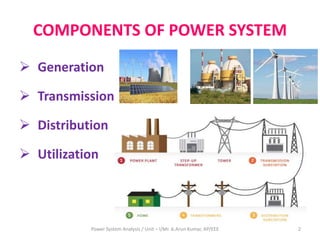
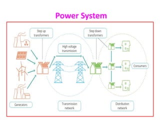
1. The key components of a power system including generation, transmission, distribution, and utilization.
2. The advantages of an interconnected power system such as increased reliability and reduced reserve capacity requirements.
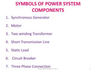
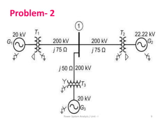
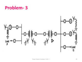
3. Common symbols used to represent power system components like generators, transformers, and transmission lines.
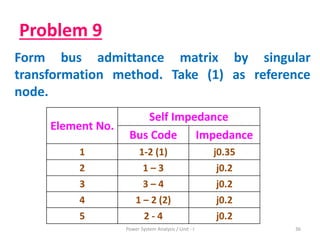
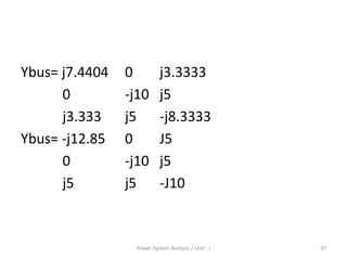
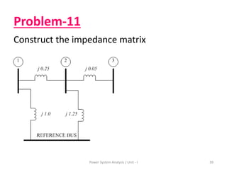
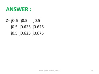
4. Concepts involved in power system analysis including per unit systems, impedance and reactance diagrams, and bus admittance matrices.


![[Deck] What's New in Spark-Iceberg Integration via DSV2.pptx](https://cdn.slidesharecdn.com/ss_thumbnails/deckwhatsnewinspark-icebergintegrationviadsv2-260210005337-25955b12-thumbnail.jpg?width=640&height=640&fit=bounds)
