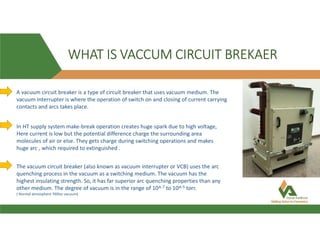
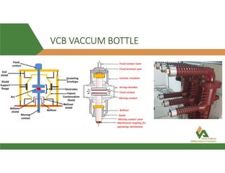
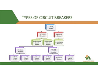
The document discusses vacuum circuit breakers (VCBs). It describes that VCBs use vacuum as an interrupting medium inside vacuum interrupters to extinguish arcs. This provides superior arc quenching over other mediums. The document discusses various components and functions of VCBs like auxiliary switches, anti-pumping relays, contact resistance testing, short circuit ratings, and accessories. It compares features of shunt and undervoltage releases and lists advantages of VCBs like being maintenance-free and having rapid arc interruption.

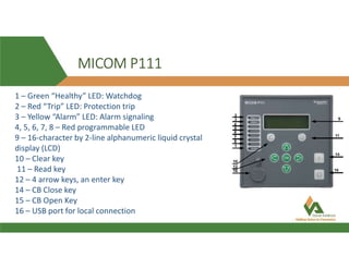
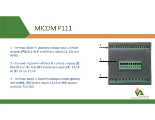
![MICOM P-111 PROTECTION
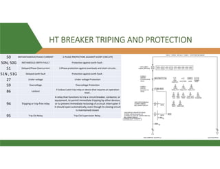
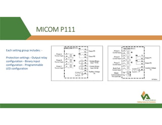
Phase O/C [50/51]:- The overcurrent protection included in the P111 relay provides non-directional three-phase overcurrent
protection with independent time-delay characteristics. All overcurrent settings apply to all of the three phases but are
independent for each of the three stages.
SOTF (Switch On To Fault function) :- With the Switch On To Fault (SOTF) submenu, it is possible to shorten the time to trip
when for example the relay has detected a fault that is still present on a feeder after energizing.
The SOTF overcurrent element is activated after the CB's state changes from open to closed. SOTF is blocked when the auto-
recloser is running (E)
E/Gnd Fault [50N/51N] :- The earth fault element operates from earth fault current that is measured directly from the
system; either by means of a separate CT located in a power system earth connection or via a residual connection of the
three line CTs. All overcurrent settings are independent for each of the two stages (Model E: three stages).
The first stage of e/f non-directional overcurrent protection has time-delayed characteristics which are selectable between
inverse definite minimum time (IDMT) and definite time (DMT). The second stage and the third (E) have definite time
characteristics only.
Negative Sequence O/C [46] (E)
Broken Conductor (E)
Thermal Overload [49]
CB Fail [50BF]](https://image.slidesharecdn.com/vcbppt-210408055935/85/Vcb-ppt-27-320.jpg)