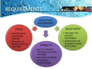
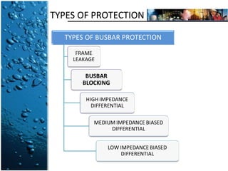
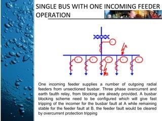
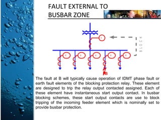
BUSBAR BLOCKING SYSTEM 
KKKL 4043 
PROTECTION AND SAFETY POWER 
SYSTEM 
LECTURER: DR HUSSAIN SHAREEF 
BY NORALINA ABDUL AZIZ A117805
INTRODUCTION 
• The protection scheme for a power system should cover the 
whole system against all probable types of fault. 
Unrestricted forms of line protection, such as overcurrent and 
distance systems, meet this requirement, although 
faults in the busbar zone are cleared only after 
some time delay. But if unit protection is applied to feeders 
and plant, the busbars are not inherently protected.
INTRODUCTION 
• Busbars have often been left without specific protection, for 
one or more of the following reasons: 
 the busbars and switchgear have a high degree of 
reliability, to the point of being regarded as 
intrinsically safe 
 it was feared that accidental operation of busbar 
protection might cause widespread dislocation of the 
power system, which, if not quickly cleared, would 
cause more loss than would the very 
infrequent actual bus faults 
 it was hoped that system protection or back-up 
protection would provide sufficient bus protection if 
needed
REQUIREMENTS
TYPES OF PROTECTION
BUSBAR BLOCKING 
• The application of busbar blocking technology has lagged 
behind that of other protection functions. But, busbar 
blocking technology is now readily available. 
• The very latest developments in the technology are included, 
such as extensive use of a data bus to link the various units 
involved, and fault tolerance against loss of a particular 
link by providing multiple communications path. 
• The development process has been very rigorous, because 
the requirements for busbar protection in respect of 
immunity to maloperation are very high.
SINGLE BUS WITH ONE INCOMING FEEDER 
OPERATION 
50 
A 
50 50 50 50 50 
B 
One incoming feeder supplies a number of outgoing radial 
feeders from unsectioned busbar. Three phase overcurrent and 
earth faulth relay, from blocking are already provided. A busbar 
blocking scheme need to be configured which will give fast 
tripping of the incomer for the busbar fault at A while remaining 
stable for the feeder fault at B. the feeder fault would be cleared 
by overcurrent protection tripping
FAULT EXTERNAL TO 
BUSBAR ZONE 
50 
50 50 50 50 50 
B L O C K 
B 
The fault at B will typically cause operation of IDMT phase fault or 
earth fault elements of the blocking protection relay. These element 
are designed to trip the relay output contacted assigned. Each of 
these element have instantaneous start output contact. In busbar 
blocking schemes, these start output contacts are use to block 
tripping of the incoming feeder element which is nominally set to 
provide busbar protection.
FAULT ON THE BUSBAR 
50 
A 
50 50 50 50 50 
B L O C K 
BACKTRIP 
Rather than wait for the incoming feeder IDMT protection element to 
clear the fault, busbar blocking are used. These blocking element will 
trip on detecting fault current above setting, provided that a block 
signal has not been received from outgoing feeder. Because the 
connection of blocking signals between relays is hardwired. The 
blocking element must allow sufficient time for any start to be issued 
by an outgoing feeder relay, and then to recognize that the block onto 
input has been energized, allowing the block to be applied. For the 
busbar fault at A, no block would be received and incoming feeder 
tripping would be subject to the short time delay set.
ADVANTAGES 
• Very lost or no cost system 
• Simple 
• Faster than faults cleared by back-up relays 
• Covers phase and earth faults 
• Adequate sensitivity – independent of number of circuits 
• No additional CT 
• Commissioning is simple – no primary current stability tests
DISADVANTAGES 
• Only suitable for simple busbars 
• Additional relays and control wiring for complex busbars 
• Beware motor in-feeds to busbar faults 
• Sensitivity limited by load current
APPLICATION 
MiCOM Busbar Blocking Scheme 
• MiCOM relay is busbar protection achieved by simple 
interconnection which already specified for their primary task 
of the feeder protection. 
MiCOM P740 range busbar 
protection relay
APPLICATION 
MiCOM Busbar Blocking Scheme 
Advantages: 
faster busbar fault clearance compared to tripping 
initiated by upstream feeder protection 
busbar protection at minimal additional cost 
Fault and disturbance records stored for busbar faults 
Blocking scheme can be easily modified
THANKS FOR 
THE TIME

Busbar Blocking System

  • 1.
    BUSBAR BLOCKING SYSTEM KKKL 4043 PROTECTION AND SAFETY POWER SYSTEM LECTURER: DR HUSSAIN SHAREEF BY NORALINA ABDUL AZIZ A117805
  • 2.
    INTRODUCTION • Theprotection scheme for a power system should cover the whole system against all probable types of fault. Unrestricted forms of line protection, such as overcurrent and distance systems, meet this requirement, although faults in the busbar zone are cleared only after some time delay. But if unit protection is applied to feeders and plant, the busbars are not inherently protected.
  • 3.
    INTRODUCTION • Busbarshave often been left without specific protection, for one or more of the following reasons:  the busbars and switchgear have a high degree of reliability, to the point of being regarded as intrinsically safe  it was feared that accidental operation of busbar protection might cause widespread dislocation of the power system, which, if not quickly cleared, would cause more loss than would the very infrequent actual bus faults  it was hoped that system protection or back-up protection would provide sufficient bus protection if needed
  • 4.
  • 5.
  • 6.
    BUSBAR BLOCKING •The application of busbar blocking technology has lagged behind that of other protection functions. But, busbar blocking technology is now readily available. • The very latest developments in the technology are included, such as extensive use of a data bus to link the various units involved, and fault tolerance against loss of a particular link by providing multiple communications path. • The development process has been very rigorous, because the requirements for busbar protection in respect of immunity to maloperation are very high.
  • 7.
    SINGLE BUS WITHONE INCOMING FEEDER OPERATION 50 A 50 50 50 50 50 B One incoming feeder supplies a number of outgoing radial feeders from unsectioned busbar. Three phase overcurrent and earth faulth relay, from blocking are already provided. A busbar blocking scheme need to be configured which will give fast tripping of the incomer for the busbar fault at A while remaining stable for the feeder fault at B. the feeder fault would be cleared by overcurrent protection tripping
  • 8.
    FAULT EXTERNAL TO BUSBAR ZONE 50 50 50 50 50 50 B L O C K B The fault at B will typically cause operation of IDMT phase fault or earth fault elements of the blocking protection relay. These element are designed to trip the relay output contacted assigned. Each of these element have instantaneous start output contact. In busbar blocking schemes, these start output contacts are use to block tripping of the incoming feeder element which is nominally set to provide busbar protection.
  • 9.
    FAULT ON THEBUSBAR 50 A 50 50 50 50 50 B L O C K BACKTRIP Rather than wait for the incoming feeder IDMT protection element to clear the fault, busbar blocking are used. These blocking element will trip on detecting fault current above setting, provided that a block signal has not been received from outgoing feeder. Because the connection of blocking signals between relays is hardwired. The blocking element must allow sufficient time for any start to be issued by an outgoing feeder relay, and then to recognize that the block onto input has been energized, allowing the block to be applied. For the busbar fault at A, no block would be received and incoming feeder tripping would be subject to the short time delay set.
  • 10.
    ADVANTAGES • Verylost or no cost system • Simple • Faster than faults cleared by back-up relays • Covers phase and earth faults • Adequate sensitivity – independent of number of circuits • No additional CT • Commissioning is simple – no primary current stability tests
  • 11.
    DISADVANTAGES • Onlysuitable for simple busbars • Additional relays and control wiring for complex busbars • Beware motor in-feeds to busbar faults • Sensitivity limited by load current
  • 12.
    APPLICATION MiCOM BusbarBlocking Scheme • MiCOM relay is busbar protection achieved by simple interconnection which already specified for their primary task of the feeder protection. MiCOM P740 range busbar protection relay
  • 13.
    APPLICATION MiCOM BusbarBlocking Scheme Advantages: faster busbar fault clearance compared to tripping initiated by upstream feeder protection busbar protection at minimal additional cost Fault and disturbance records stored for busbar faults Blocking scheme can be easily modified
  • 14.