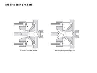
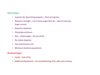
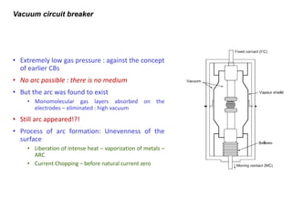
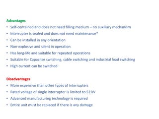
Circuit Breaker
• Gear is a set of equipment for a particular activity
Switchgear
Switchgear is that equipment used for carrying out electrical switching operations
Arc
Switch, Isolator and Circuit Breaker
• Isolator Used for physical isolation after disconnection by CB
• Earthing switch Closed while HV equipment is isolated
• Switch Used for switching on and off under healthy condition
• Contactor Used for automated switching operations
• Circuit breaker Has to be able to successfully operate under all conditions
Switch
Many disciplines of science and engineering like plasma physics, material science, fluid
mechanics, heat and mass transfer, mechanical engineering, electrodynamics and
electrical power systems engineering are involved in the design and operation of a
circuit breaker.
Trip circuit of the CB
Steady and transient states of a circuit breaker
The process of breaking current
1
1. Trip coil energized
2
2. Contacts start separating
3
3. First natural current zero
Arc gets extinguished but restrikes
4
4. Second natural current zero
Arc gets extinguished but restrikes
5
5. Third natural current zero
Arc gets extinguished and does not restrikes
Voltage across the CB
Current through the CB
 Arcing:
• Thermal stress is predominant factor.
• Interrupter attempts to remove heat which is
generated by arcing.
• Further arc diameter is reduced to low value
 Current zero: Arc get extinguished.
 Post arc:
• Voltage stress is predominant factor.
• Flushing the contact space with fresh dielectric
strength medium.
Arc
• The arc consists of ions dissociated from the gas molecules. because of the
high temperature and high energy.
• The physical state of the arc is known as plasma. The plasma is called the
fourth state of the matter, the other three being solid, liquid and gas.
• The typical temperature within the plasma is of the order of 5000 K.
• The conductivity of the plasma is 13 orders of magnitude more than that of
the air, approaching the conductivity of carbon.
Necessity of Arc
The current would have been abruptly forced to zero after the contact separation,
causing severe over-voltages, possibly damaging the breaker itself as well as other
components of the power system
The arc delays the interruption of current up to its natural current zero instant. At the
current zero instant, the energy stored in the system inductance is zero and hence the
interruption does not cause any high voltage as a result of reappearance of energy
stored in the inductor.
The resulting voltage can be expressed as:
Effect of Power Factor on Recovery Voltage
Recovery voltage the voltage which appears across the breaker contacts after the arc
interruption. The recovery voltage depends on power factor. This tends to reignite the arc.
Interruption of lagging zero power
factor current
Interruption of leading zero power
factor current
Interruption of short circuit current of a transmission line.
Restriking Voltage
Restriking Voltage
The natural frequency of oscillation of the
restriking voltage is much higher
Rate of Rise of Restriking Voltage
Circuit Breaker Ratings
• Under fault – CB required to perform
• Capable of opening the faulty circuit and breaking
the fault current
• Must be capable of being closed on to a fault
• Capable carrying fault current for a short time
while another CB (in series) is clearing fault
• Breaking capacity
• Making capacity
• Short – time capacity
Breaking capacity
• RMS current that a CB is capable of breaking at given recovery voltage and under
specified conditions (power factor, RRRV)
• Unsymmetrical current – ac and dc component
• √3 x V x I x 10-6 MVA
Making Capacity
• Possibility of closing CB under fault
• Ability to withstand and close successfully against the electromagnetic force
• In terms of peak value current
• The peak value of current (including dc component) during the first cycle of current
after the closure of CB is known an making capacity
• Making capacity = √2 x 1.8 x Symmetrical breaking capacity
Rated MVA
The product of the pre-fault circuit breaker voltage and post-fault circuit breaker current.
The MVA is expressed on a three-phase basis as: √3*VL-L, pre-fault * IL, post-fault
Rated Continuous Current
The rated continuous current of a circuit breaker is the established limit of current in rms
amperes at rated power frequency that it shall be required to carry continuously without
exceeding specified temperature limits
Rated Voltage
The rated maximum voltage of the circuit breaker is the highest rms phase-to-phase
voltage for which the circuit breaker is designed, and is the upper limit for operation.
Short – time rating
• It is the period for which the circuit breaker is able to carry fault while remaining
closed
Operating Time
Rated Frequency
The frequency at which it is designed to operate. Standard power frequencies are 50 Hz
and 60 Hz.
The time elapsed between the instant when the trip circuit is energized and the instant at
which successful interruption of the current.
Rated Operating Duty
Factor influencing the arc extinction:
• Speed of contact separation
• Material of contact
• Pattern of flow of quenching medium
• Energy liberated from arcing and energy in system inductance
• RRRV
• Rate of regain of dielectric strength
• Instant of contact separation with respect to voltage and current
Arc Extinction
• Methods of Arc Extinction
• High Resistance Method
• Arc resistance is made to increase with time
• Reduction in current to a value insufficient to maintain the arc
• Mostly used low/medium voltage in DC Circuit interruption
• Low Resistance or zero point interruption Method
• Deionization by fresh unionized medium. i.e., Oil, fresh air, SF6
• Mostly used in AC circuit interruption.
Use of Resistor during Breaking
The characteristics equation for the above differential equation is
Use of Resistor during Breaking
Thus, the restriking voltage and RRRV and RRRVmax can be controlled by suitably choosing the value
of the breaking resistor.
The response will be non-oscillatory if
The response will be critically damped if
The response will be oscillatory if
The roots of the above equation are:
Air breaker Circuit breaker - High Resistance
Air-blast circuit breaker
Advantages
• The risk of fire eliminated
• Arcing products are eliminated
• Growth of dielectric strength is high
• Arcing time is very less
• Suitable for very frequent operation is
needed
Disadvantages
• Air has relatively inferior arc extinguishing
properties
• Very sensitive to the variations in the rate of rise of
restriking voltage
• Maintenance is required for the compressor
Bulk oil circuit breakers
• Heat – evaporates the surrounding oil – dissociates into gas – H2
• H2 Creates a good cooling medium – reduce the ionization process
Advantages
• Decomposition of oil – good cooling medium
• Acts as an good insulator (like transformer)
Disadvantages
• It is inflammable – high risk of fire
• It may form explosive mixture with air
• Arcing products remains in the oil – degrades the property of the oil
Minimum oil circuit breaker
Advantages
• Requires Lesser quantity of oil
• Smaller space
• Reduced risk of fire
• Maintenance problem is reduced
Disadvantages
• Due to low oil degree of carbonization is increased
• Removal of gas from the operating point is difficulty
• Dielectric strength of the oil degrades
Circuit chamber requires minimum oil
SF6 circuit breaker
Physical Properties of SF6
• Colourless
• Odourless
• Non Toxic – Pure SF6 – Not harmful to health
• Non – Inflammable
• State – gas at Normal Temperature and Pressure
• Heat Transferability – 2 to 2.5 times that of air at same pressure
SF6 circuit breaker
Chemical Properties of SF6
• Stable upto 5000C
• Inert – the components do not get oxidised
• Maintenance is reduced
• Electronegative Gas – ability of attract and hold electrons
• Does not react with structural materials – upto 5000C
• Products of Decomposition – Sulphur and Fluorine – corrosive
• Metallic Fluorides – it must be removed periodically
Constructional features of an SF6 circuit breaker
Arc extinction principle
Advantages
• Superior Arc Quenching property – Short arcing time
• Dielectric Strength – 2 to 3 times larger than Air – able to interrupt
larger current
• Noiseless operation
• Closed gas enclosure
• Non – inflammable – No risk of fire
• No carbon deposits
• Low maintenance cost
• Minimum Auxiliary equipments
Disadvantages
• Costly – Cost of SF6
• Additional Equipment – For reconditioning of SF6 after every Arcing
Vacuum circuit breaker
• Extremely low gas pressure : against the concept
of earlier CBs
• No arc possible : there is no medium
• But the arc was found to exist
• Monomolecular gas layers absorbed on the
electrodes – eliminated : high vacuum
• Still arc appeared!?!
• Process of arc formation: Unevenness of the
surface
• Liberation of intense heat – vaporization of metals –
ARC
• Current Chopping – before natural current zero
Advantages
• Self-contained and does not need filling medium – no auxiliary mechanism
• Interrupter is sealed and does not need maintenance*
• Can be installed in any orientation
• Non-explosive and silent in operation
• Has long-life and suitable for repeated operations
• Suitable for Capacitor switching, cable switching and industrial load switching
• High current can be switched
Disadvantages
• More expensive than other types of interrupters
• Rated voltage of single interrupter is limited to 52 kV
• Advanced manufacturing technology is required
• Entire unit must be replaced if there is any damage
Circuit Breaker Application Chart

EE6102 Circuit breaker.pdf .............

  • 1.
  • 2.
    • Gear isa set of equipment for a particular activity Switchgear Switchgear is that equipment used for carrying out electrical switching operations
  • 3.
  • 4.
    Switch, Isolator andCircuit Breaker • Isolator Used for physical isolation after disconnection by CB • Earthing switch Closed while HV equipment is isolated • Switch Used for switching on and off under healthy condition • Contactor Used for automated switching operations • Circuit breaker Has to be able to successfully operate under all conditions
  • 5.
    Switch Many disciplines ofscience and engineering like plasma physics, material science, fluid mechanics, heat and mass transfer, mechanical engineering, electrodynamics and electrical power systems engineering are involved in the design and operation of a circuit breaker.
  • 6.
  • 7.
    Steady and transientstates of a circuit breaker
  • 8.
    The process ofbreaking current 1 1. Trip coil energized 2 2. Contacts start separating 3 3. First natural current zero Arc gets extinguished but restrikes 4 4. Second natural current zero Arc gets extinguished but restrikes 5 5. Third natural current zero Arc gets extinguished and does not restrikes Voltage across the CB Current through the CB  Arcing: • Thermal stress is predominant factor. • Interrupter attempts to remove heat which is generated by arcing. • Further arc diameter is reduced to low value  Current zero: Arc get extinguished.  Post arc: • Voltage stress is predominant factor. • Flushing the contact space with fresh dielectric strength medium.
  • 9.
    Arc • The arcconsists of ions dissociated from the gas molecules. because of the high temperature and high energy. • The physical state of the arc is known as plasma. The plasma is called the fourth state of the matter, the other three being solid, liquid and gas. • The typical temperature within the plasma is of the order of 5000 K. • The conductivity of the plasma is 13 orders of magnitude more than that of the air, approaching the conductivity of carbon.
  • 10.
    Necessity of Arc Thecurrent would have been abruptly forced to zero after the contact separation, causing severe over-voltages, possibly damaging the breaker itself as well as other components of the power system The arc delays the interruption of current up to its natural current zero instant. At the current zero instant, the energy stored in the system inductance is zero and hence the interruption does not cause any high voltage as a result of reappearance of energy stored in the inductor. The resulting voltage can be expressed as:
  • 11.
    Effect of PowerFactor on Recovery Voltage Recovery voltage the voltage which appears across the breaker contacts after the arc interruption. The recovery voltage depends on power factor. This tends to reignite the arc.
  • 12.
    Interruption of laggingzero power factor current Interruption of leading zero power factor current
  • 13.
    Interruption of shortcircuit current of a transmission line.
  • 14.
  • 15.
  • 16.
    The natural frequencyof oscillation of the restriking voltage is much higher
  • 17.
    Rate of Riseof Restriking Voltage
  • 19.
    Circuit Breaker Ratings •Under fault – CB required to perform • Capable of opening the faulty circuit and breaking the fault current • Must be capable of being closed on to a fault • Capable carrying fault current for a short time while another CB (in series) is clearing fault • Breaking capacity • Making capacity • Short – time capacity
  • 20.
    Breaking capacity • RMScurrent that a CB is capable of breaking at given recovery voltage and under specified conditions (power factor, RRRV) • Unsymmetrical current – ac and dc component • √3 x V x I x 10-6 MVA
  • 21.
    Making Capacity • Possibilityof closing CB under fault • Ability to withstand and close successfully against the electromagnetic force • In terms of peak value current • The peak value of current (including dc component) during the first cycle of current after the closure of CB is known an making capacity • Making capacity = √2 x 1.8 x Symmetrical breaking capacity
  • 22.
    Rated MVA The productof the pre-fault circuit breaker voltage and post-fault circuit breaker current. The MVA is expressed on a three-phase basis as: √3*VL-L, pre-fault * IL, post-fault Rated Continuous Current The rated continuous current of a circuit breaker is the established limit of current in rms amperes at rated power frequency that it shall be required to carry continuously without exceeding specified temperature limits Rated Voltage The rated maximum voltage of the circuit breaker is the highest rms phase-to-phase voltage for which the circuit breaker is designed, and is the upper limit for operation. Short – time rating • It is the period for which the circuit breaker is able to carry fault while remaining closed
  • 23.
    Operating Time Rated Frequency Thefrequency at which it is designed to operate. Standard power frequencies are 50 Hz and 60 Hz. The time elapsed between the instant when the trip circuit is energized and the instant at which successful interruption of the current.
  • 24.
  • 25.
    Factor influencing thearc extinction: • Speed of contact separation • Material of contact • Pattern of flow of quenching medium • Energy liberated from arcing and energy in system inductance • RRRV • Rate of regain of dielectric strength • Instant of contact separation with respect to voltage and current
  • 26.
    Arc Extinction • Methodsof Arc Extinction • High Resistance Method • Arc resistance is made to increase with time • Reduction in current to a value insufficient to maintain the arc • Mostly used low/medium voltage in DC Circuit interruption • Low Resistance or zero point interruption Method • Deionization by fresh unionized medium. i.e., Oil, fresh air, SF6 • Mostly used in AC circuit interruption.
  • 27.
    Use of Resistorduring Breaking
  • 28.
    Use of Resistorduring Breaking The characteristics equation for the above differential equation is
  • 29.
    Use of Resistorduring Breaking Thus, the restriking voltage and RRRV and RRRVmax can be controlled by suitably choosing the value of the breaking resistor. The response will be non-oscillatory if The response will be critically damped if The response will be oscillatory if The roots of the above equation are:
  • 30.
    Air breaker Circuitbreaker - High Resistance
  • 31.
    Air-blast circuit breaker Advantages •The risk of fire eliminated • Arcing products are eliminated • Growth of dielectric strength is high • Arcing time is very less • Suitable for very frequent operation is needed Disadvantages • Air has relatively inferior arc extinguishing properties • Very sensitive to the variations in the rate of rise of restriking voltage • Maintenance is required for the compressor
  • 32.
    Bulk oil circuitbreakers • Heat – evaporates the surrounding oil – dissociates into gas – H2 • H2 Creates a good cooling medium – reduce the ionization process
  • 33.
    Advantages • Decomposition ofoil – good cooling medium • Acts as an good insulator (like transformer) Disadvantages • It is inflammable – high risk of fire • It may form explosive mixture with air • Arcing products remains in the oil – degrades the property of the oil
  • 34.
    Minimum oil circuitbreaker Advantages • Requires Lesser quantity of oil • Smaller space • Reduced risk of fire • Maintenance problem is reduced Disadvantages • Due to low oil degree of carbonization is increased • Removal of gas from the operating point is difficulty • Dielectric strength of the oil degrades Circuit chamber requires minimum oil
  • 35.
    SF6 circuit breaker PhysicalProperties of SF6 • Colourless • Odourless • Non Toxic – Pure SF6 – Not harmful to health • Non – Inflammable • State – gas at Normal Temperature and Pressure • Heat Transferability – 2 to 2.5 times that of air at same pressure
  • 36.
    SF6 circuit breaker ChemicalProperties of SF6 • Stable upto 5000C • Inert – the components do not get oxidised • Maintenance is reduced • Electronegative Gas – ability of attract and hold electrons • Does not react with structural materials – upto 5000C • Products of Decomposition – Sulphur and Fluorine – corrosive • Metallic Fluorides – it must be removed periodically
  • 37.
    Constructional features ofan SF6 circuit breaker
  • 38.
  • 39.
    Advantages • Superior ArcQuenching property – Short arcing time • Dielectric Strength – 2 to 3 times larger than Air – able to interrupt larger current • Noiseless operation • Closed gas enclosure • Non – inflammable – No risk of fire • No carbon deposits • Low maintenance cost • Minimum Auxiliary equipments Disadvantages • Costly – Cost of SF6 • Additional Equipment – For reconditioning of SF6 after every Arcing
  • 40.
    Vacuum circuit breaker •Extremely low gas pressure : against the concept of earlier CBs • No arc possible : there is no medium • But the arc was found to exist • Monomolecular gas layers absorbed on the electrodes – eliminated : high vacuum • Still arc appeared!?! • Process of arc formation: Unevenness of the surface • Liberation of intense heat – vaporization of metals – ARC • Current Chopping – before natural current zero
  • 41.
    Advantages • Self-contained anddoes not need filling medium – no auxiliary mechanism • Interrupter is sealed and does not need maintenance* • Can be installed in any orientation • Non-explosive and silent in operation • Has long-life and suitable for repeated operations • Suitable for Capacitor switching, cable switching and industrial load switching • High current can be switched Disadvantages • More expensive than other types of interrupters • Rated voltage of single interrupter is limited to 52 kV • Advanced manufacturing technology is required • Entire unit must be replaced if there is any damage
  • 42.