Download to read offline


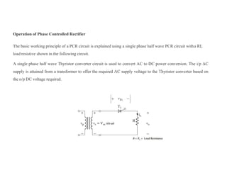


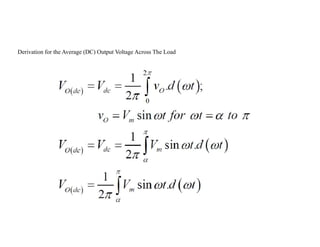


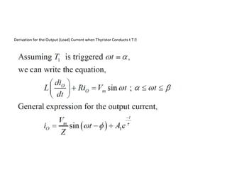

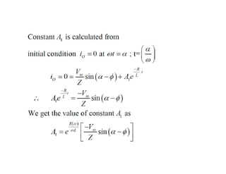

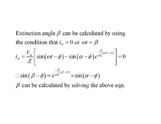


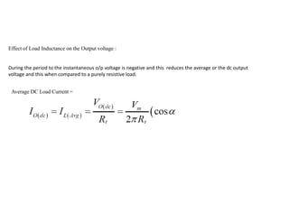

The document discusses different types of phase controlled rectifiers. There are two types - single-phase and three-phase controlled rectifiers. Single-phase rectifiers can be half-wave or full-wave, while three-phase rectifiers can be semi, full, or dual converters. The operation of a single-phase half-wave thyristor converter with a resistive load is explained, including derivations of average output voltage, RMS output voltage, and load current. Effects of an inductive load are also discussed.


