2
Dr. S. N.Patil Department of Electronics T.
C. College
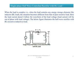
Single-phase Half Wave Controlled Rectifier with RL Load :
When the load is complex i.e., when the load contains any energy storage elements like
inductor (RL load), the situation becomes different from that of pure resistive load. Here
the load current doesn’t follow the waveform of the load voltage (load current will be
out of phase with load voltage). The below figure illustrates the half-wave rectifier with
RL (resistive-inductive) load.
3.
Dr. S. N.Patil Department of Electron
ics T. C. College
3
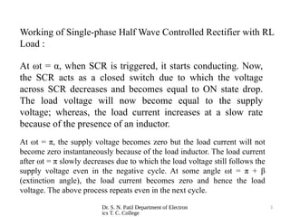
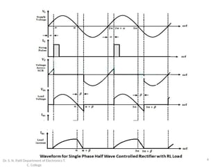
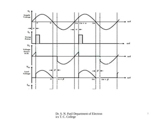
At ωt = α, when SCR is triggered, it starts conducting. Now,
the SCR acts as a closed switch due to which the voltage
across SCR decreases and becomes equal to ON state drop.
The load voltage will now become equal to the supply
voltage; whereas, the load current increases at a slow rate
because of the presence of an inductor.
At ωt = π, the supply voltage becomes zero but the load current will not
become zero instantaneously because of the load inductor. The load current
after ωt = π slowly decreases due to which the load voltage still follows the
supply voltage even in the negative cycle. At some angle ωt = π + β
(extinction angle), the load current becomes zero and hence the load
voltage. The above process repeats even in the next cycle.
Working of Single-phase Half Wave Controlled Rectifier with RL
Load :
4.
4
Dr. S. N.Patil Department of Electronics T.
C. College
5.
Dr. S. N.Patil Department of Electron
ics T. C. College
5
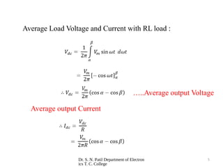
Average Load Voltage and Current with RL load :
…..Average output Voltage
Average output Current
6.
Dr. S. N.Patil Department of Electron
ics T. C. College
6
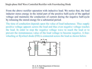
Single-phase Half Wave Controlled Rectifier with Freewheeling Diode
FD
R
L
From the above rectifier operation with inductive load. We notice that, the load
inductor stores energy in the initial part of the positive half-cycle of the applied
voltage and maintains the conduction of current during the negative half-cycle
by releasing the stored energy for a substantial period.
The time of conduction depends upon the value of load inductance. Thus supply
positive voltage appears across the load and thus even negative voltage reaches
the load. In order to stop the negative voltage wave to reach the load or to
prevent the instantaneous value of the load voltage to become negative. A free-
wheeling or flywheel diode (FD) is connected across the load as shown below.
7.
Dr. S. N.Patil Department of Electron
ics T. C. College
7
8.
Dr. S. N.Patil Department of Electron
ics T. C. College
8
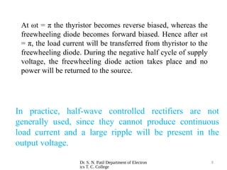
In practice, half-wave controlled rectifiers are not
generally used, since they cannot produce continuous
load current and a large ripple will be present in the
output voltage.
At ωt = π the thyristor becomes reverse biased, whereas the
freewheeling diode becomes forward biased. Hence after ωt
= π, the load current will be transferred from thyristor to the
freewheeling diode. During the negative half cycle of supply
voltage, the freewheeling diode action takes place and no
power will be returned to the source.
9.
Dr. S. N.Patil Department of Electron
ics T. C. College
9
THANK YOU!!