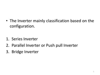
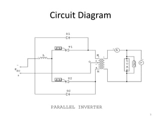
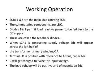
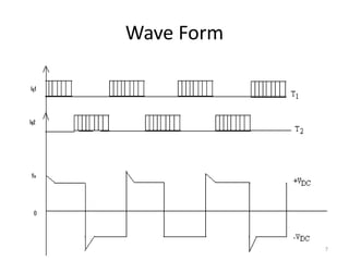
Name :- Smit Shah -140410109096
T.Y Electrical 2 Sem 6
Subject:-Power Electronics 2
Topic :-Parallel Inverter
1
• The Inverter mainly classification based on the
configuration.
1. Series Inverter
2. Parallel Inverter or Push pull Inverter
3. Bridge Inverter
2
Circuit Diagram
3
Working Operation
• SCRs 1 &2 are the main load carrying SCR.
• The commutating components are L&C.
• Diodes 1& 2 permit load reactive power to be fed back to the
DC supply.
• These are called the feedback diodes.
• When sCR1 is conducting supply voltage Edc will appear
across the left half of
• the transformer primary winding OA.
• Terminal O is positive with reference to A thus, capacitor
• C will get charged to twice the input voltage.
• The load voltage will be positive and of magnitude Edc.
4
Working Operation
• At the end of the half period, SCR2 is fired.
• Capacitor C will immediately apply a reverse voltage of 2Edc
across SCR 1 and turns it off.
• When SCR 1 is turned off the capacitor will discharge through
SCR2, inductor L, Diode D1 and a portion of the transformer
winding LA.
• Thus the energy stored in the capacitance will be fed back to
the load through the transformer
• coupling of windings LA and PQ.
• During this period, the potential of point L will be fixed by the
• DC input supply and voltage will still be positive.
5
Working Operation
• The load current which earlier was flowing
• through SCR1 will flow through OL and diode D1 to the
negative input terminal.
• The current through the inductor L will now flow through D2,
M, B & S2 .
• The trapped energy in L will be fedback to the load. Since the
point M is now connected to the negative supply terminal, the
load voltage polarity will be reversed.
• Also the capacitor will be charged in the opposite direction.
6
Wave Form
7
Advantage of parallel Inverter
• The load voltage waveform is not depend on
load , as it does in series inverter.
• Only 2 scr are required as compared to at least
four in brige inverter configuration.
• It uses the simple class c commutation.
• It is simple & economical circuit.
• Commutation components do not have to
carry the entire load current.
8
9

Parallel Inverter

  • 1.
    Name :- SmitShah -140410109096 T.Y Electrical 2 Sem 6 Subject:-Power Electronics 2 Topic :-Parallel Inverter 1
  • 2.
    • The Invertermainly classification based on the configuration. 1. Series Inverter 2. Parallel Inverter or Push pull Inverter 3. Bridge Inverter 2
  • 3.
  • 4.
    Working Operation • SCRs1 &2 are the main load carrying SCR. • The commutating components are L&C. • Diodes 1& 2 permit load reactive power to be fed back to the DC supply. • These are called the feedback diodes. • When sCR1 is conducting supply voltage Edc will appear across the left half of • the transformer primary winding OA. • Terminal O is positive with reference to A thus, capacitor • C will get charged to twice the input voltage. • The load voltage will be positive and of magnitude Edc. 4
  • 5.
    Working Operation • Atthe end of the half period, SCR2 is fired. • Capacitor C will immediately apply a reverse voltage of 2Edc across SCR 1 and turns it off. • When SCR 1 is turned off the capacitor will discharge through SCR2, inductor L, Diode D1 and a portion of the transformer winding LA. • Thus the energy stored in the capacitance will be fed back to the load through the transformer • coupling of windings LA and PQ. • During this period, the potential of point L will be fixed by the • DC input supply and voltage will still be positive. 5
  • 6.
    Working Operation • Theload current which earlier was flowing • through SCR1 will flow through OL and diode D1 to the negative input terminal. • The current through the inductor L will now flow through D2, M, B & S2 . • The trapped energy in L will be fedback to the load. Since the point M is now connected to the negative supply terminal, the load voltage polarity will be reversed. • Also the capacitor will be charged in the opposite direction. 6
  • 7.
  • 8.
    Advantage of parallelInverter • The load voltage waveform is not depend on load , as it does in series inverter. • Only 2 scr are required as compared to at least four in brige inverter configuration. • It uses the simple class c commutation. • It is simple & economical circuit. • Commutation components do not have to carry the entire load current. 8
  • 9.