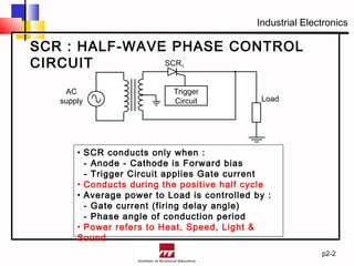
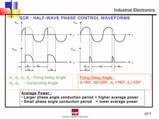
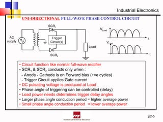
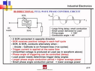
Industrial Electronics
p2-1
SCR Phase Control
Circuit
- Half-wave Circuit
- Full-wave Circuit)
Industrial Electronics
SCR : HALF-WAVE PHASE CONTROL
CIRCUIT
p2-2
Trigger
Circuit
SCR1
AC
supply Load
• SCR conducts only when :
- Anode - Cathode is Forward bias
- Trigger Circuit applies Gate current
• Conducts during the positive half cycle
• Average power to Load is controlled by :
- Gate current (firing delay angle)
- Phase angle of conduction period
• Power refers to Heat, Speed, Light &
Sound
Industrial Electronics
SCR : HALF-WAVE PHASE CONTROL WAVEFORMS
p2-3
t
VAK
t
t
Vload
d1 d2
d5 d5
VAK
Vload
d6 d4
d3
d6
t
d1, d2, d3, d4 - Firing Delay Angle
d5, d6 - Conducting Angle
Firing Delay Angle :
d1=800
, d2=2600
, d3,=1600
, d4=3300
Average Power :
• Larger phase angle conduction period = higher average power
• Small phase angle conduction period = lower average power
Industrial Electronics
SCR : FULL-WAVE PHASE
CONTROL CIRCUIT
p2-4
2 types of Full-wave control
circuits :
• Unidirectional
• Bi-directional
Industrial Electronics
UNI-DIRECTIONAL FULL-WAVE PHASE CONTROL CIRCUIT
p2-5
Trigger
Circuit(s)
SCR1
SCR2
AC
supply
Load
VLoad
t
VLoad
t
• Circuit function like normal full-wave rectifier
• SCR1 & SCR2 conducts only when :
- Anode - Cathode is on Forward bias (+ve cycles)
- Trigger Circuit applies Gate current
• DC pulsating voltage is produced at Load
• Phase angle of triggering can be controlled (delay)
• Load power needs determines trigger delay angles
• Larger phase angle conduction period = higher average power
• Small phase angle conduction period = lower average power
Industrial Electronics
BI-DIRECTIONAL FULL-WAVE PHASE CONTROL CIRCUIT
p2-6
Trigger
Circuit(s)
SCR1
SCR2
AC
supply
VLoad
t
• Large firing delay; small conduction
• Small power delivered to Load
• Firing angle = 1350
• Conduction angle = 450
• 2 SCR connected in opposite direction
• SCR receives positive voltage in each half cycle
• SCR1 & SCR2 conducts alternately when :
- Anode - Cathode is on Forward bias (+ve cycles)
• Trigger current is applied at the same time
• Unrectified voltage is produced at Load (as in waveform above)
• Phase angle of triggering can be controlled (delay)
• Load power needs determines trigger delay angles
• Larger phase angle conduction period = higher average power
• Small phase angle conduction period = lower average power

Silicon Control Rectifier Phase Control

  • 1.
    Industrial Electronics p2-1 SCR PhaseControl Circuit - Half-wave Circuit - Full-wave Circuit)
  • 2.
    Industrial Electronics SCR :HALF-WAVE PHASE CONTROL CIRCUIT p2-2 Trigger Circuit SCR1 AC supply Load • SCR conducts only when : - Anode - Cathode is Forward bias - Trigger Circuit applies Gate current • Conducts during the positive half cycle • Average power to Load is controlled by : - Gate current (firing delay angle) - Phase angle of conduction period • Power refers to Heat, Speed, Light & Sound
  • 3.
    Industrial Electronics SCR :HALF-WAVE PHASE CONTROL WAVEFORMS p2-3 t VAK t t Vload d1 d2 d5 d5 VAK Vload d6 d4 d3 d6 t d1, d2, d3, d4 - Firing Delay Angle d5, d6 - Conducting Angle Firing Delay Angle : d1=800 , d2=2600 , d3,=1600 , d4=3300 Average Power : • Larger phase angle conduction period = higher average power • Small phase angle conduction period = lower average power
  • 4.
    Industrial Electronics SCR :FULL-WAVE PHASE CONTROL CIRCUIT p2-4 2 types of Full-wave control circuits : • Unidirectional • Bi-directional
  • 5.
    Industrial Electronics UNI-DIRECTIONAL FULL-WAVEPHASE CONTROL CIRCUIT p2-5 Trigger Circuit(s) SCR1 SCR2 AC supply Load VLoad t VLoad t • Circuit function like normal full-wave rectifier • SCR1 & SCR2 conducts only when : - Anode - Cathode is on Forward bias (+ve cycles) - Trigger Circuit applies Gate current • DC pulsating voltage is produced at Load • Phase angle of triggering can be controlled (delay) • Load power needs determines trigger delay angles • Larger phase angle conduction period = higher average power • Small phase angle conduction period = lower average power
  • 6.
    Industrial Electronics BI-DIRECTIONAL FULL-WAVEPHASE CONTROL CIRCUIT p2-6 Trigger Circuit(s) SCR1 SCR2 AC supply VLoad t • Large firing delay; small conduction • Small power delivered to Load • Firing angle = 1350 • Conduction angle = 450 • 2 SCR connected in opposite direction • SCR receives positive voltage in each half cycle • SCR1 & SCR2 conducts alternately when : - Anode - Cathode is on Forward bias (+ve cycles) • Trigger current is applied at the same time • Unrectified voltage is produced at Load (as in waveform above) • Phase angle of triggering can be controlled (delay) • Load power needs determines trigger delay angles • Larger phase angle conduction period = higher average power • Small phase angle conduction period = lower average power
  • 7.
    Industrial Electronics BI-DIRECTIONAL FULL-WAVEPHASE CONTROL CIRCUIT p2-6 Trigger Circuit(s) SCR1 SCR2 AC supply VLoad t • Large firing delay; small conduction • Small power delivered to Load • Firing angle = 1350 • Conduction angle = 450 • 2 SCR connected in opposite direction • SCR receives positive voltage in each half cycle • SCR1 & SCR2 conducts alternately when : - Anode - Cathode is on Forward bias (+ve cycles) • Trigger current is applied at the same time • Unrectified voltage is produced at Load (as in waveform above) • Phase angle of triggering can be controlled (delay) • Load power needs determines trigger delay angles • Larger phase angle conduction period = higher average power • Small phase angle conduction period = lower average power