Downloaded 618 times


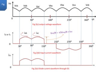
![Average output voltage V0 =(1/periodicity) ∫VmL sin(ᾠt+30⁰) d(ᾠt)
=(3/∏) ∫VmL sin(ᾠt+30⁰) d(ᾠt)
= (3/∏)VmL = (3√2/ ∏)VL = (3√6/∏)Vp
Where, VmL = maximum value of line voltage
VL = rms value of line voltage
Vp = rms value of phase voltage
R.M.S value of output voltage(Vor) =[3/∏ ∫VmL sinᾠt d(ᾠt)]
= 0.9558 VmL
Ripple Voltage (Vr) = √(Vrms – Vavg.) = 0.0408 VmL
Voltage ripple factor (VRF) = Vr/Vo = 0.0408 VmL/(3/∏)VmL = 0.0427 or 4.27%
Form Factor = Vor/Vo = 1.0009
R.M.S value of O/P current (Ior) = 0.9558Vml/R = 0.9558 ImL
ᾳ2
ᾳ1
∏/2
∏/6
∏/3
2∏/3
22 1/2
2 2](https://image.slidesharecdn.com/threephasefullwaverectifier-161019195451/85/Three-phase-full-wave-rectifier-9-320.jpg)
![Pdc = Vo Io = (3/∏) VmL ImL
Pac = Vr Ir = 0.9558 VmL ImL
Rectifier efficiency = Pdc/Pac = 0.9982
% Rectifier efficiency = 0.9982 ×100 = 99.82%
Rms value of source voltage(Vs) = Vmp/√2 = VmL/√6 (Since, VmL= √3Vmp)
Rms value of line current(Is) = rms value of T/F secondary current
= [2/∏ ∫ ImL sinᾠt d(ᾠt)]
= 0.7804 ImL
VA rating of transformer = 3Vs Is = 3 (VmL/√6) × 0.7804 ImL
= 0.955791 VmL ImL
Transformer Utilization Factor(TUF)= (Pdc / Transformer VA Rating)
= (3/∏)^2 /0.955791 = 0.9541
2
2 2
1/2
∏/3
2∏/3
2](https://image.slidesharecdn.com/threephasefullwaverectifier-161019195451/85/Three-phase-full-wave-rectifier-10-320.jpg)
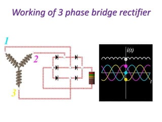
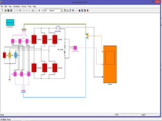


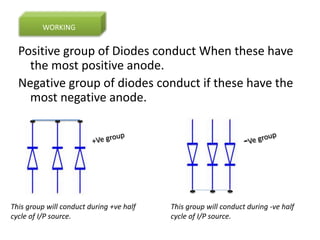
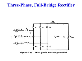
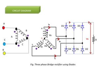
The document describes a three-phase, full-wave rectifier circuit using 6 diodes arranged in a bridge configuration. The upper diodes (D1, D3, D5) form the positive group and conduct during the positive half cycles of the input voltage. The lower diodes (D2, D4, D6) form the negative group and conduct during the negative half cycles. Calculations are provided for the output voltage, current, power, ripple, efficiency and transformer utilization factor of the three-phase full-wave rectifier.


