Downloaded 159 times
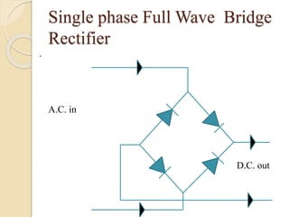
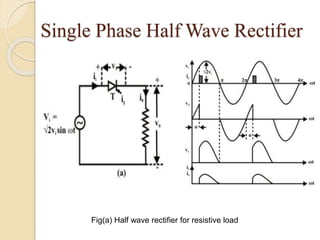
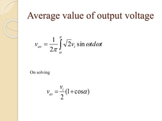
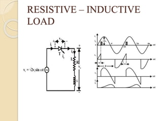
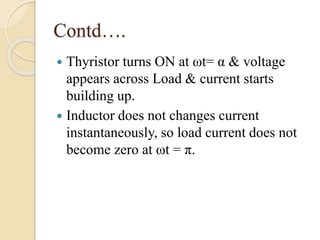
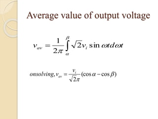
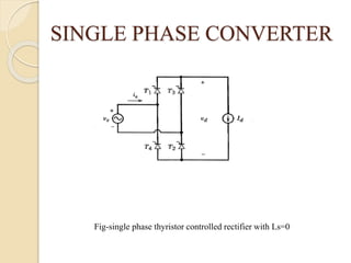
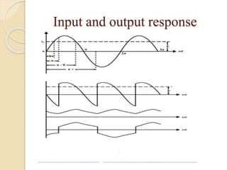
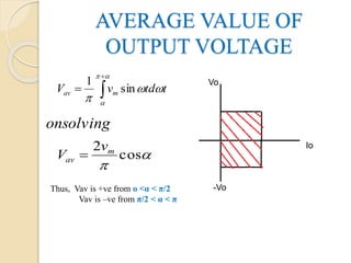
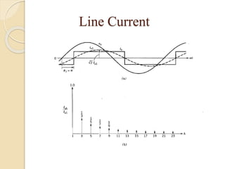
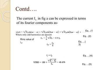
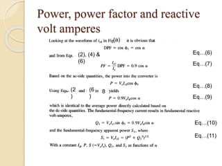
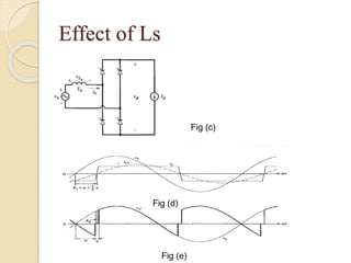


This document summarizes a seminar on single phase converters. It discusses different types of single phase converters including half wave and full wave rectifiers as well as controlled rectifiers using thyristors. It provides equations for calculating the average output voltage and current for resistive and resistive-inductive loads. The operation and triggering of thyristors in a single phase converter is explained. Graphs of input voltage and output voltage and current are shown. The effect of an output inductor and finite commutation interval are also discussed.