Downloaded 144 times


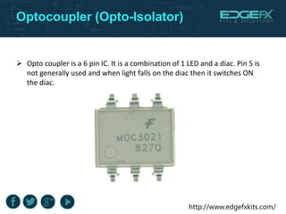


The document discusses the design and operation of a dual converter using thyristors, which enables speed control for AC induction motors commonly used in domestic appliances. It outlines the hardware and software requirements, including the use of a microcontroller from the 8051 family and various components like SCRs and opto-isolators. The conclusion emphasizes the dual converter's capability to provide adjustable DC polarity for motor control and the benefits of its full controllability in both forward and reverse directions.