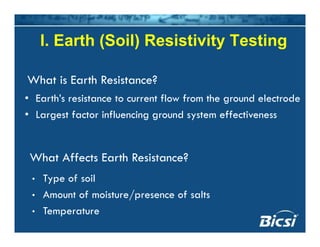
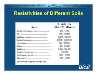
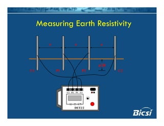
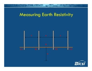
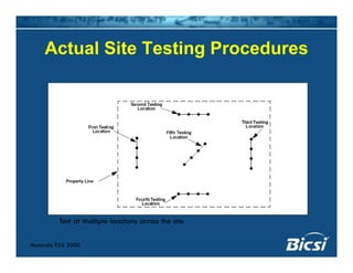
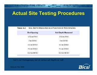
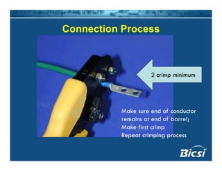
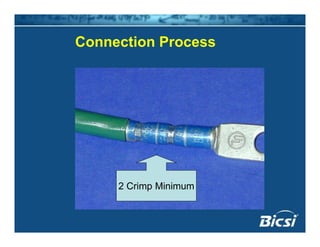
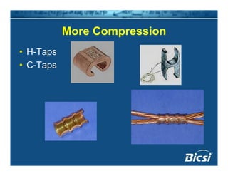
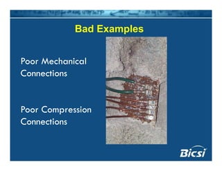
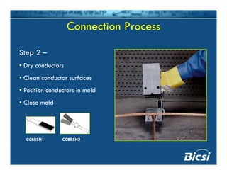
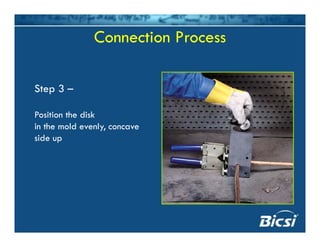
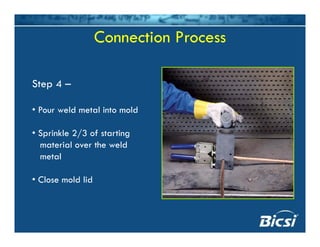
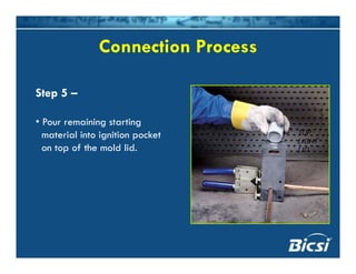
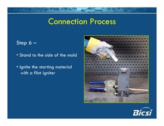
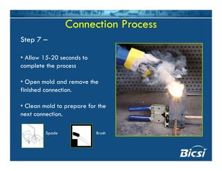
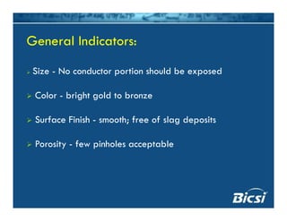
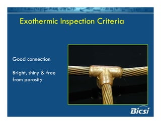
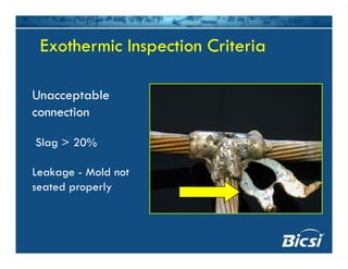
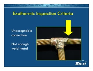
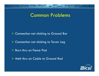
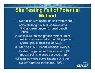
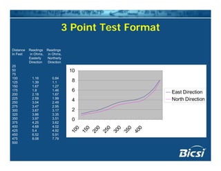
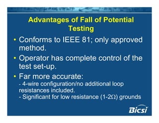
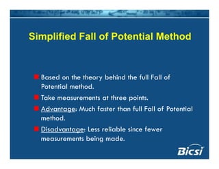
Grounding and Bonding
Testing
Presented by Mike Lewis
Senior Application Engineer
Meggergg
ObjectiveObjective
• Review Proper soil resistivity techniques
Id tif d l t d t• Identify ground electrode system
components and bonding materials
• Ensure proper installation
• Measure the effectiveness of the groundg
electrode and bonding system by means
of ground testingg g
Simply PutSimply Put…
• Step 1 Earth (Soil) Testp ( )
• Step 2 Install System
• Step 3 Test System• Step 3 Test System
I. Earth (Soil) Resistivity TestingI. Earth (Soil) Resistivity Testing
Wh i E h R i ?
• Earth’s resistance to current flow from the ground electrode
What is Earth Resistance?
• Largest factor influencing ground system effectiveness
What Affects Earth Resistance?
• Type of soil
• Amount of moisture/presence of salts
• Temperature
Resistivities of Different SoilsResistivities of Different Soils
Why Earth (Soil) Test?Why Earth (Soil) Test?
Tells you how “good” (conductive) your
soil issoil is
Good indication on whether or not
generic ground specification designg g p g
will work
Helps reduce “surprises” at the end ofp p
the installation
5 Ohm Requirements5 Ohm Requirements
Soil Resistivity ranges:
100 - 15,000 Ohms cm – Standard Design Ok
15 000 25 000 Oh M b15,000- 25,000 Ohms cm- Maybe
25 000 - 50 000 Ohms cm- Special25,000 - 50,000 Ohms cm- Special
50,000 + - Very Special; maybe not practical50,000 y Sp a ; ayb o p a a
Earth (Soil) Resistivity TestingEarth (Soil) Resistivity Testing
• How do we test the soil?• How do we test the soil?
4 P W T• 4 Part Wenner Test
Measuring Earth ResistivityMeasuring Earth Resistivity
Use a 4 terminal gro nd testerUse a 4-terminal ground tester.
Space the electrodes an equal distance
“a” aparta apart.
Insert the electrodes a distance of a/20
into the groundinto the ground.
Measures the average soil resistivity to a
depth equal to the electrode separationdepth equal to the electrode separation.
Measuring Earth ResistivityMeasuring Earth Resistivity
a a a
a/20
C2P2P1C1 C2P2P1C1
C2 P2 C1P1
DET2/2
M i E h R i i iMeasuring Earth Resistivity
a a a
C2P2P1C1
X
C2P2P1C1
a
Actual Site Testing ProceduresActual Site Testing Procedures
Test at Multiple locations across the site
Motorola R56 2000
Test at Multiple locations across the site
Actual Site Testing ProceduresActual Site Testing Procedures
Soil is not Homogenous; test at various soil depths as well
Motorola R56 2000
Soil Resistivity Test SummarySoil Resistivity Test Summary
• If the Results of the Soil Test are in the
15,000 Ohm-cm range or less, it is
prudent to go with the generic ground
system specified
• If the Results of the Soil Test areIf the Results of the Soil Test are
substantially above 15,000 Ohm-cm;
contact the carrier owner and thecontact the carrier, owner and the
engineering firm.
Ground Electrode System
Components
• Ground Electrodes
• Ground ConductorsGround Conductors
• Ground Bars
• Bonding Connectors
Mechanical–Mechanical
–Compression
–Exothermic
Ground ElectrodesGround Electrodes
1. Ground Electrodes
Types -yp
Ground Rods:
Copper Clad Steel
Solid Copper
GalvanizedGalvanized
Stainless Steel
Enhanced
Ground PlatesGround Plates
Copper Ground Mesh
Ground Electrodes… ConsiderationsGround Electrodes… Considerations
Soil Resistivity - Some soils, (such as sandy soils), have such high
resistivities that conventional ground rods or ground electrode
Ground Electrodes… ConsiderationsGround Electrodes… Considerations
g g
systems may be unable to attain the desired ground resistance
requirement. Enhanced ground electrodes or ground
enhancement materials may be required to meet the groundingenhancement materials may be required to meet the grounding
specification.
/Soil PH/type - PH a factor in choosing. Some ground rod types
work better in different soils.
Soil Characteristics - Some sites may have only a few inches of
soil (or none) sitting on top of bedrock. In this case, ground
mesh is the preferred electrode (Never drill into bedrock)mesh is the preferred electrode. (Never drill into bedrock).
Ground Mesh
Ground Electrodes…
Considerations
Ground Rod Diameter - Doubling diameter of ground rod
reduces resistance only 10%. Using larger diameter ground
rods is mainly a strength issue (ie. In rocky conditions, a largerrods is mainly a strength issue (ie. In rocky conditions, a larger
diameter ground rod might be advantageous).
G d R d L th D bli l th th ti ll dGround Rod Length - Doubling length theoretically reduces
resistance 40%, actual reduction depends on soil resistivities
encountered in multi-
layered soils.
Ground Rod Spacing - Approximately twice the length (inGround Rod Spacing Approximately twice the length (in
good soil).
Ground Rod Driving TipGround Rod Driving Tip
• Don’t do this!
Ground Rod Spacing Rule of ThumbGround Rod Spacing Rule of Thumb
Proper Spacing
1x length
Too Close
Ground Electrodes… ConsiderationsGround Electrodes… Considerations
Ufer Grounds - Concrete
encased electrode. Forencased electrode. For
example, tying into the tower
footing rebar or building
pad rebar provides a Ufer
ground. Ufer grounds should
b d th lnever be used as the sole
ground electrode.
Enhanced Grounding Materialg
Should be >
95%95% pure
carbon
Should not
contain concrete
or bentonite
fillers
ApplicationsApplications
Vertical Application Horizontal Application
Enhanced Ground RodsEnhanced Ground Rods
Contain electrolytic salts that lower ground resistivity over time
Grounding ConductorsGrounding ConductorsGrounding ConductorsGrounding Conductors
Types -
Grounding: Solid
Stranded
Flat Strap
Lightning: Rope Lay
Inductance Flat strap conductors have less inductance than their similarly
Conductors... ConsiderationsConductors... Considerations
Inductance - Flat strap conductors have less inductance than their similarly
sized round conductor counterparts.
Strength/Durability - Round conductors whether solid or stranded are muchStrength/Durability Round conductors whether solid or stranded are much
stronger than a 24 or 26 gauge flat strap conductor. This should be a
consideration when backfilling trenches.
Exothermic Connections - The preferred type of connection for underground
uses. Availability as well as ease of connection is better for the round
conductors than the flat strap conductors.
Cost Effectiveness - Although the inductance may be less for the flat strap
conductors, their cost is much higher. It may be more cost effective to use
lti l d d t th l i ll d t i d thmultiple round conductors, thus lowering overall ground system impedance than
single flat strap conductors.
Lightning Tra els on the o tside s rface of a
Conductors…ConsiderationsConductors…Considerations
Lightning Travels on the outside surface of a
conductor, the so called “skin affect”. Therefore, the
larger the surface area of a conductor, the betterlarger the surface area of a conductor, the better
path it makes.
Remember, multiple parallel paths are very
important. The fewer paths you have the larger the
f di h d dsurface area or diameter the conductor needs to
have.
Remember, a Tower is the down conductor.
Conductor…ConsiderationsConductor…Considerations
- Selection of Proper Size
I h b f S f d R- In the absence of a Specified Requirement…
- No Standards exist in Wireless Telecommunications. (ANSI
J Std 607)J-Std 607)
- LP Standards state if building height is equal or greaterg g q g
than >75’ use class II
- Size Should be Dependent on the length and number of- Size Should be Dependent on the length and number of
paths
Conductor… ConsiderationsConductor… Considerations
Conductor Routing and PlacementConductor Routing and Placement
General Rules of Thumb for Placement:
As far as possible from communications cable
(12” minimum for a ground conductor. Reference NEC 800(12 minimum for a ground conductor. Reference NEC 800
for Power lines).
Lightning conductors must be 6’ away from power &Lightning conductors must be 6 away from power &
communications cable. (Reference NEC 800 & NEC 250).
C i di l f hi if d dCross in a perpendicular fashion if needed.
Not Good….Not Good….
Pl tPl tPlacement….Placement….
Placement….Placement….
Even Better….Even Better….
A little Better….A little Better….
Placement….Placement….
Good example….Good example….
Routing….Routing….
C d C id iC d C id iConductor…ConsiderationsConductor…Considerations
Routing and Placement
General Rules of Thumb for Routing:
M i t i d d l i th t d ( i t ti lMaintain downward sloping path to ground (equipotential
bonds exception)
Do not run conductors uphill (1/4 rise acceptable to
a point)
Maintain at least an 8” radius of bend
- Uphill path to ground
- Radius of bend less
than 8”
- Bonding issue
- Water pipe?
Not bonded to conduit….Not bonded to conduit….
Harger Lightning & Grounding © 2006
Conductor…ConsiderationsConductor…Considerations
Routing in conduit…
- Sometimes required by local codes
If i t lli d it it t b b d d- If run in metallic conduit, it must be bonded
on both ends
- Might be beneficial if run in metallic conduit
- Conduit on left a little
better….
- Needs to be bonded
as close to the
opening as possible...
- Two conduits on right
t b d d t d itnot bonded to conduit
Better yet….Better yet….
- A really good
idea !!!idea !!!
- Used “romex”
style fittings
Ground BarsGround Bars
Ground BarGround Bar
• What is a Ground Bar?
– Simply a connection point
• What does it do?What does it do?
– Facilitates ease of bonding connections
• Issues• Issues
– Theft
Tamper resistantTamper resistant
– Galvanized
Bad idea, galvanic coupleg p
Grounding/Bonding ConnectionsGrounding/Bonding Connections
Three Types of Connectionsy
MechanicalMechanical
Compression
Exothermic
Mechanical ConnectionsMechanical Connections
• Use StandardUse Standard
Tools & Hardware
Mechanical ConnectionsMechanical Connections
• Used when compression or exothermic
connections are not practical/feasible
• Surface preparation essentialp p
• Use appropriate hardware
• Tighten to proper torque rating• Tighten to proper torque rating
Mechanical ConnectionsMechanical Connections
• Advantagesg
– Can be removed
– Use common tools
– Lower material Cost
• Disadvantagesg
– Can be removed
– Loosen over time
– Require more maintenance
Surface Preparationp
Hardware RequirementsHardware Requirements
• Stainless Steel• Stainless Steel
or
• Silicon Bronze• Silicon Bronze
• No Zinc!
Galvanic SeriesGalvanic Series
• Galvanic SeriesGalvanic Series
– >.3 volts difference in
potential can causep
corrosion
– Use stainless steel
hardware instead of zinc
Zinc HardwareZinc Hardware
Proper Torque
Proper TorqueProper Torque
More MechanicalsMore Mechanicals
• Possible “burn
h h” ithrough” issues
More MechanicalsMore Mechanicals
Motorola R56 2000
Mechanicals MoreMechanicals More
More MechanicalsMore Mechanicals
• Dissimilar
metals
Compression ConnectionsCompression Connections
• Used when it is desirable to make an
irreversible electrical connectionirreversible electrical connection
• Less maintenance than a mechanical
connection
• Not a molecular bond, (Not recommended
for underground use)
Compression ConnectionsCompression Connections
• Specialized tools/dies requiredSpecialized tools/dies required
– Generate, 2, 6 and 13 tons of
crimping forcep g
Compression ConnectionsCompression Connections
AdvantagesAdvantages
Irreversible
UL listedUL listed
Low/no maintenance
Di dDisadvantages
Expensive tooling
Sometimes hard to make, (location)
Not a molecular bond
Compression LugsCompression Lugs
Long Barrel
Inspection Port
g
p
2-Hole
Connection ProcessConnection Process
Trim insulation back so that
b d d t i li htlbared conductor is slightly
longer than barrel.
Connection ProcessConnection Process
Insert conductor so that it
butts up against end of barrel.
View this thru inspection portView this thru inspection port.
Connection ProcessConnection Process
2 crimp minimum2 crimp minimum
Make sure end of conductor
i t d f b lremains at end of barrel;
Make first crimp
Repeat crimping process
Connection ProcessConnection Process
2 Crimp Minimum
More CompressionMore Compression
• H-TapsH Taps
• C-Taps
Bad ExamplesBad Examples
Poor Mechanical
ConnectionsConnections
Poor Compression
Connections
Exothermic ConnectionsExothermic Connections
What is an exothermic
connection?
An exothermic connection
is used to form a
molecular bond between
two metals such as
copper and steel.pp
Exothermic Connections
Provides a Molecular Bond
Ampacity exceeds that of conductors
Connections will not loosenConnections will not loosen
Connections never increase in resistance
Does not deteriorate with age
Maintenance free
Compression vs. Exothermicp
Molecular BondPoint-to-Point Contact Molecular BondPoint-to-Point Contact
The Exothermic ProcessThe Exothermic Process
Tools Required
Tools
Mold
Handle
Weld Metal
Flint Igniter
Disks
Exothermic Connection ProcessExothermic Connection Process
Safety First
Protective Glasses
Gloves
C ACover Arms
Connection Process
Step 1 –
Connection Process
Step 1 –
Torch dry the
mold to eliminate moisture!
(First connection and…)
torch
Connection Process
Step 2 –Step 2
• Dry conductors
Cl d t f• Clean conductor surfaces
• Position conductors in mold
• Close mold
CCBRSH1 CCBRSH2
Connection Process
Step 3 –
Position the disk
in the mold evenly, concave
side upside up
Connection Process
Step 4 –
P ld t l i t ld• Pour weld metal into mold
• Sprinkle 2/3 of starting
material over the weld
metal
• Close mold lid
Connection ProcessConnection Process
Step 5 –
P i i t ti• Pour remaining starting
material into ignition pocket
on top of the mold lid.
TOPTOP
LIGHTLIGHT
LIDLID
Connection ProcessConnection Process
Step 6 –
• Stand to the side of the mold• Stand to the side of the mold
• Ignite the starting material
with a flint igniter
Connection Process
Step 7 –
• Allow 15-20 seconds to
complete the process
• Open mold and remove the
finished connection.
• Clean mold to prepare for the
next connection.
Spade Brush
Exothermic InspectionExothermic Inspection
ProcessProcess
General Indicators:General Indicators:
Si N d i h ld b dSize - No conductor portion should be exposed
Color - bright gold to bronzeColor - bright gold to bronze
Surface Finish - smooth; free of slag depositsg p
Porosity - few pinholes acceptable
Exothermic Inspection CriteriaExothermic Inspection CriteriaExothermic Inspection CriteriaExothermic Inspection Criteria
Good connection
Bright, shiny & free
from porosity
Exothermic Inspection CriteriaExothermic Inspection CriteriaExothermic Inspection CriteriaExothermic Inspection Criteria
Unacceptable
connection
Slag > 20%
Leakage - Mold not
t d lseated properly
Exothermic Inspection CriteriaExothermic Inspection CriteriaExothermic Inspection CriteriaExothermic Inspection Criteria
UnacceptableUnacceptable
connection
Not enough
weld metalweld metal
C P blCommon Problems
Connection not sticking to Ground BarConnection not sticking to Ground Bar
Connection not sticking to Tower LegConnection not sticking to Tower Leg
Burn thru on Fence Post
Melt thru on Cable to Ground Rod
Ground Electrode System
Testing
• Ok, So the System is installed
• Let’s Test!
Choose the Proper Instruments:Choose the Proper Instruments:
• Use a dedicated ground tester
(designed to make this measurement)(designed to make this measurement).
• Don’t make the measurement with a
generalized ohmmeter or multimetergeneralized ohmmeter or multimeter -
results will be erroneous.
Don’t use an insulation tester• Don t use an insulation tester.
3-Terminal Earth Tester3 Terminal Earth Tester
Current SupplyCurrent Supply
Ammeter (I)Ammeter (I)
Voltmeter (E)
P C
Current
Probe
Potential
Probe
Ground
Electrode
Under Test
P C
EarthEarth
Probe
X
4-Terminal Earth Tester
Current Supply
Ammeter (I)( )
G d
Voltmeter (E)
P2 C2
C1 P1
Auxiliary
Current
ElectrodeAuxiliary
Potential
Electrode
Ground
Electrode
Under Test
2 2
EarthEarth
X
Theoretical BackgroundTheoretical Background
Ground Rod Sphere of Influence
I
Current
I
Current
Theoretical BackgroundTheoretical Background
Current Probe Sphere of Influence
Auxiliary
Current
Auxiliary
Potential
Ground
Electrode
Under
Test (X) Current
Probe (C)
Potential
Probe (P)
( )
Theoretical Background - Resistance Curve
Ohmsistancein
True Resistance
Resi
Current
Probe
Distance of Potential Probe from X (dp)
Ground
El t d
X C
Probe
Position
Electrode
Position
Theoretical Backgroundg
Insufficient Probe Spacing
Ground
Current
Probe (C)
Potential
Probe (P)
Ground
Electrode
Under
Test (X)
nOhmssistancein
Distance of Potential Probe from X (dp)
Res
Test Methods Serve Two Primary
Purposes:Purposes:
Verify that correct spacing is being used to assure
reliable results.
Provide specific shortcuts to reduce testing time.
Ground Testing Methodsg
Fall of Potential Method
61 8% R l /M th d61.8% Rule/Method
Four Potential Method
I i C M h dIntersecting Curves Method
Slope Method
Dead Earth Method
Star-Delta Method
Fall of Potential Method
Advantage: Extremely reliableAdvantage: Extremely reliable.
Disadvantage: Extremely time consuming and
labor intensivelabor intensive.
Theoretical Background - Fall of Potential
Current
Probe (C)
Potential
Probe (P)
Positions
Ground
Electrode
Under
Test (X) Probe (C)Test (X)
stanceinOhm
Current
Probe
Distance of Potential Probe from X (dp)
Ground
El d
X C
Resist
Probe
Position
Electrode
Position
Site Testing Fall of Potential
Method
1. Determine size of ground grid system and
calculate length of test leads required.
(Pythagorean theorem). Lead Length
CriticalCritical.
2. Make sure that the ground system under
test is non connected to the Utility ground
system grid. (Telephone as well).
3. Starting at 50’, record readings every 50’
t bt i d i t (Oto obtain a ground resistance curve. (Or
enough points to ensure a good graph.
4.The point where curve flattens out is the4.The point where curve flattens out is the
system’s ground resistance. (62%)
3 Point Test Format
Distance Readings Readings
I F t i Oh i Oh
10
In Feet in Ohms, in Ohms,
Easterly Northerly
Direction Direction
25
50
75
6
8
East Direction
75
100 1.16 0.84
125 1.39 1.1
150 1.67 1.27
175 1.8 1.46
200 2.18 1.67
0
2
4 North Direction225 2.59 1.99
250 3.04 2.49
275 3.47 2.95
300 3.67 3.17
325 3.86 3.35
350 3 97 3 51 0
100
150
200
250
300
350
400
350 3.97 3.51
375 4.25 3.62
400 4.68 4.02
425 5.4 4.92
450 6.52 5.91
475 8 08 7 79475 8.08 7.79
500
Advantages of Fall of Potentialg
Testing
Conforms to IEEE 81 onl appro ed• Conforms to IEEE 81; only approved
method.
• Operator has complete control of the
test set-up.p
• Far more accurate:
- 4-wire configuration/no additional loop- 4 wire configuration/no additional loop
resistances included.
- Significant for low resistance (1-2Ω) grounds
Simplified Fall of Potential Method
Based on the theory behind the full Fall of
Potential method.
k hTake measurements at three points.
Advantage: Much faster than full Fall of Potential
th dmethod.
Disadvantage: Less reliable since fewer
measurements being mademeasurements being made.
Simplified Fall of Potential Methodp
dc
C2P2X
50%
60%40%
50%
C2 P2 C1P1
DET2/2
Simplified Fall of Potential Methodp
• RA = R1 + R2 + R3
33
• RMax Deviation = RA - RX
(RX is furthest R value from RA)( X A)
• % deviation = (RMax Deviation )*100
RARA
• If (% deviation)*1.2 > 10%; C2 must be
moved further awaymoved further away
61.8% Rule/Method
Based on the theory behind the full Fall of
P t ti l th dPotential method.
Take measurement at only one point.
Ad E l i k dAdvantage: Extremely quick and easy.
Disadvantage: Assumes that conditions are
f t ( d t b i d ilperfect (adequate probe spacing and soil
homogeneity).
61 8% R l /M th d61.8% Rule/Method
dcdc
dp = 61.8%dc
CPX
C2 P2 C1P1
DET2/2
Theoretical Background - 61 8% RuleTheoretical Background - 61.8% Rule
Ground
Electrode
Current
Probe (C)
Potential
Probe (P)
Under
Test (X)
anceinOhms
Current Probe
Resistance
Resista
61.8%
Ground Electrode
Resistance
Distance of Potential Probe from X (dp)
X C
The Problem of LimitedThe Problem of Limited
Distance/Space
Ground
Current
Probe (C)
Potential
Probe (P)
Ground
Electrode
Under
Test (X)
sanceinOhms
Distance of Potential Probe from X (dp)
Resist
Stakeless/Clamp-On MethodStakeless/Clamp-On Method
Stakeless
Tester
V
I
R6R5R4R3R2R1
Di d tDisadvantages
Stakeless/Clamp-On Method
• Effective only in situations with multiple
grounds in parallel (pole grounds)grounds in parallel (pole grounds).
• Cannot be used on isolated grounds.
- no return path- no return path
• Cannot be used if an alternate lower
resistance return exists not involving theresistance return exists not involving the
soil.
Cellular towers- Cellular towers
- Substations
DisadvantagesDisadvantages
Stakeless/Clamp-On Method
• Subject to influence if another part of
the ground system is in “resistance
area”.
• Test is less representative of a fault at
power frequency.power frequency.
• Accuracies are greatly reduced.
Disadvantagesg
Stakeless/Clamp-On Method
• Requires a good return path.
• Connection must be on the correct
part of the loop.p p
• Susceptible to noise from nearby
substations and transformers (nosubstations and transformers (no
reading).
Clamp-on Applicationp pp
Motorola R56 2000
Ground Testing SummaryGround Testing Summary
• 3 Point Fall of Potential Method most accurate
– Must disconnect from Utility Grid
– Testing Area often an issue
• Clamp-On Style has limited Applications
L t ti l f i– Large potential for misuse
– Not as accurate as 3 point method
• Testing must be done correctly to determine if theTesting must be done correctly to determine if the
desired ground resistance specification is met
SummarySummary
• Proper Testing and Installation methods
are often over-lookedare often over-looked.
• Following these guidelines will help
l f t i ith di dlessen future issues with grounding and
bonding related events.
• For more information please contact
BICSI or Megger.gg

Grounding and bonding testing

  • 1.
    Grounding and Bonding Testing Presentedby Mike Lewis Senior Application Engineer Meggergg
  • 2.
    ObjectiveObjective • Review Propersoil resistivity techniques Id tif d l t d t• Identify ground electrode system components and bonding materials • Ensure proper installation • Measure the effectiveness of the groundg electrode and bonding system by means of ground testingg g
  • 3.
    Simply PutSimply Put… •Step 1 Earth (Soil) Testp ( ) • Step 2 Install System • Step 3 Test System• Step 3 Test System
  • 4.
    I. Earth (Soil)Resistivity TestingI. Earth (Soil) Resistivity Testing Wh i E h R i ? • Earth’s resistance to current flow from the ground electrode What is Earth Resistance? • Largest factor influencing ground system effectiveness What Affects Earth Resistance? • Type of soil • Amount of moisture/presence of salts • Temperature
  • 5.
    Resistivities of DifferentSoilsResistivities of Different Soils
  • 6.
    Why Earth (Soil)Test?Why Earth (Soil) Test? Tells you how “good” (conductive) your soil issoil is Good indication on whether or not generic ground specification designg g p g will work Helps reduce “surprises” at the end ofp p the installation
  • 7.
    5 Ohm Requirements5Ohm Requirements Soil Resistivity ranges: 100 - 15,000 Ohms cm – Standard Design Ok 15 000 25 000 Oh M b15,000- 25,000 Ohms cm- Maybe 25 000 - 50 000 Ohms cm- Special25,000 - 50,000 Ohms cm- Special 50,000 + - Very Special; maybe not practical50,000 y Sp a ; ayb o p a a
  • 8.
    Earth (Soil) ResistivityTestingEarth (Soil) Resistivity Testing • How do we test the soil?• How do we test the soil? 4 P W T• 4 Part Wenner Test
  • 9.
    Measuring Earth ResistivityMeasuringEarth Resistivity Use a 4 terminal gro nd testerUse a 4-terminal ground tester. Space the electrodes an equal distance “a” aparta apart. Insert the electrodes a distance of a/20 into the groundinto the ground. Measures the average soil resistivity to a depth equal to the electrode separationdepth equal to the electrode separation.
  • 10.
    Measuring Earth ResistivityMeasuringEarth Resistivity a a a a/20 C2P2P1C1 C2P2P1C1 C2 P2 C1P1 DET2/2
  • 11.
    M i Eh R i i iMeasuring Earth Resistivity a a a C2P2P1C1 X C2P2P1C1 a
  • 12.
    Actual Site TestingProceduresActual Site Testing Procedures Test at Multiple locations across the site Motorola R56 2000 Test at Multiple locations across the site
  • 13.
    Actual Site TestingProceduresActual Site Testing Procedures Soil is not Homogenous; test at various soil depths as well Motorola R56 2000
  • 14.
    Soil Resistivity TestSummarySoil Resistivity Test Summary • If the Results of the Soil Test are in the 15,000 Ohm-cm range or less, it is prudent to go with the generic ground system specified • If the Results of the Soil Test areIf the Results of the Soil Test are substantially above 15,000 Ohm-cm; contact the carrier owner and thecontact the carrier, owner and the engineering firm.
  • 15.
    Ground Electrode System Components •Ground Electrodes • Ground ConductorsGround Conductors • Ground Bars • Bonding Connectors Mechanical–Mechanical –Compression –Exothermic
  • 16.
    Ground ElectrodesGround Electrodes 1.Ground Electrodes Types -yp Ground Rods: Copper Clad Steel Solid Copper GalvanizedGalvanized Stainless Steel Enhanced Ground PlatesGround Plates Copper Ground Mesh
  • 17.
    Ground Electrodes… ConsiderationsGroundElectrodes… Considerations Soil Resistivity - Some soils, (such as sandy soils), have such high resistivities that conventional ground rods or ground electrode Ground Electrodes… ConsiderationsGround Electrodes… Considerations g g systems may be unable to attain the desired ground resistance requirement. Enhanced ground electrodes or ground enhancement materials may be required to meet the groundingenhancement materials may be required to meet the grounding specification. /Soil PH/type - PH a factor in choosing. Some ground rod types work better in different soils. Soil Characteristics - Some sites may have only a few inches of soil (or none) sitting on top of bedrock. In this case, ground mesh is the preferred electrode (Never drill into bedrock)mesh is the preferred electrode. (Never drill into bedrock).
  • 18.
  • 19.
    Ground Electrodes… Considerations Ground RodDiameter - Doubling diameter of ground rod reduces resistance only 10%. Using larger diameter ground rods is mainly a strength issue (ie. In rocky conditions, a largerrods is mainly a strength issue (ie. In rocky conditions, a larger diameter ground rod might be advantageous). G d R d L th D bli l th th ti ll dGround Rod Length - Doubling length theoretically reduces resistance 40%, actual reduction depends on soil resistivities encountered in multi- layered soils. Ground Rod Spacing - Approximately twice the length (inGround Rod Spacing Approximately twice the length (in good soil).
  • 20.
    Ground Rod DrivingTipGround Rod Driving Tip • Don’t do this!
  • 21.
    Ground Rod SpacingRule of ThumbGround Rod Spacing Rule of Thumb Proper Spacing 1x length Too Close
  • 22.
    Ground Electrodes… ConsiderationsGroundElectrodes… Considerations Ufer Grounds - Concrete encased electrode. Forencased electrode. For example, tying into the tower footing rebar or building pad rebar provides a Ufer ground. Ufer grounds should b d th lnever be used as the sole ground electrode.
  • 23.
    Enhanced Grounding Materialg Shouldbe > 95%95% pure carbon Should not contain concrete or bentonite fillers
  • 24.
  • 25.
    Enhanced Ground RodsEnhancedGround Rods Contain electrolytic salts that lower ground resistivity over time
  • 26.
    Grounding ConductorsGrounding ConductorsGroundingConductorsGrounding Conductors Types - Grounding: Solid Stranded Flat Strap Lightning: Rope Lay
  • 27.
    Inductance Flat strapconductors have less inductance than their similarly Conductors... ConsiderationsConductors... Considerations Inductance - Flat strap conductors have less inductance than their similarly sized round conductor counterparts. Strength/Durability - Round conductors whether solid or stranded are muchStrength/Durability Round conductors whether solid or stranded are much stronger than a 24 or 26 gauge flat strap conductor. This should be a consideration when backfilling trenches. Exothermic Connections - The preferred type of connection for underground uses. Availability as well as ease of connection is better for the round conductors than the flat strap conductors. Cost Effectiveness - Although the inductance may be less for the flat strap conductors, their cost is much higher. It may be more cost effective to use lti l d d t th l i ll d t i d thmultiple round conductors, thus lowering overall ground system impedance than single flat strap conductors.
  • 28.
    Lightning Tra elson the o tside s rface of a Conductors…ConsiderationsConductors…Considerations Lightning Travels on the outside surface of a conductor, the so called “skin affect”. Therefore, the larger the surface area of a conductor, the betterlarger the surface area of a conductor, the better path it makes. Remember, multiple parallel paths are very important. The fewer paths you have the larger the f di h d dsurface area or diameter the conductor needs to have. Remember, a Tower is the down conductor.
  • 29.
    Conductor…ConsiderationsConductor…Considerations - Selection ofProper Size I h b f S f d R- In the absence of a Specified Requirement… - No Standards exist in Wireless Telecommunications. (ANSI J Std 607)J-Std 607) - LP Standards state if building height is equal or greaterg g q g than >75’ use class II - Size Should be Dependent on the length and number of- Size Should be Dependent on the length and number of paths
  • 30.
    Conductor… ConsiderationsConductor… Considerations ConductorRouting and PlacementConductor Routing and Placement General Rules of Thumb for Placement: As far as possible from communications cable (12” minimum for a ground conductor. Reference NEC 800(12 minimum for a ground conductor. Reference NEC 800 for Power lines). Lightning conductors must be 6’ away from power &Lightning conductors must be 6 away from power & communications cable. (Reference NEC 800 & NEC 250). C i di l f hi if d dCross in a perpendicular fashion if needed.
  • 31.
    Not Good….Not Good…. PltPl tPlacement….Placement….
  • 32.
  • 33.
    A little Better….Alittle Better…. Placement….Placement….
  • 34.
  • 35.
    C d Cid iC d C id iConductor…ConsiderationsConductor…Considerations Routing and Placement General Rules of Thumb for Routing: M i t i d d l i th t d ( i t ti lMaintain downward sloping path to ground (equipotential bonds exception) Do not run conductors uphill (1/4 rise acceptable to a point) Maintain at least an 8” radius of bend
  • 36.
    - Uphill pathto ground - Radius of bend less than 8” - Bonding issue - Water pipe?
  • 37.
    Not bonded toconduit….Not bonded to conduit…. Harger Lightning & Grounding © 2006
  • 38.
    Conductor…ConsiderationsConductor…Considerations Routing in conduit… -Sometimes required by local codes If i t lli d it it t b b d d- If run in metallic conduit, it must be bonded on both ends - Might be beneficial if run in metallic conduit
  • 39.
    - Conduit onleft a little better…. - Needs to be bonded as close to the opening as possible... - Two conduits on right t b d d t d itnot bonded to conduit
  • 40.
  • 41.
    - A reallygood idea !!!idea !!! - Used “romex” style fittings
  • 42.
  • 43.
    Ground BarGround Bar •What is a Ground Bar? – Simply a connection point • What does it do?What does it do? – Facilitates ease of bonding connections • Issues• Issues – Theft Tamper resistantTamper resistant – Galvanized Bad idea, galvanic coupleg p
  • 44.
    Grounding/Bonding ConnectionsGrounding/Bonding Connections ThreeTypes of Connectionsy MechanicalMechanical Compression Exothermic
  • 45.
    Mechanical ConnectionsMechanical Connections •Use StandardUse Standard Tools & Hardware
  • 46.
    Mechanical ConnectionsMechanical Connections •Used when compression or exothermic connections are not practical/feasible • Surface preparation essentialp p • Use appropriate hardware • Tighten to proper torque rating• Tighten to proper torque rating
  • 47.
    Mechanical ConnectionsMechanical Connections •Advantagesg – Can be removed – Use common tools – Lower material Cost • Disadvantagesg – Can be removed – Loosen over time – Require more maintenance
  • 48.
  • 49.
  • 50.
    Hardware RequirementsHardware Requirements •Stainless Steel• Stainless Steel or • Silicon Bronze• Silicon Bronze • No Zinc!
  • 51.
    Galvanic SeriesGalvanic Series •Galvanic SeriesGalvanic Series – >.3 volts difference in potential can causep corrosion – Use stainless steel hardware instead of zinc
  • 52.
  • 53.
  • 54.
  • 55.
    More MechanicalsMore Mechanicals •Possible “burn h h” ithrough” issues
  • 56.
  • 57.
  • 58.
  • 59.
    Compression ConnectionsCompression Connections •Used when it is desirable to make an irreversible electrical connectionirreversible electrical connection • Less maintenance than a mechanical connection • Not a molecular bond, (Not recommended for underground use)
  • 60.
    Compression ConnectionsCompression Connections •Specialized tools/dies requiredSpecialized tools/dies required – Generate, 2, 6 and 13 tons of crimping forcep g
  • 61.
    Compression ConnectionsCompression Connections AdvantagesAdvantages Irreversible ULlistedUL listed Low/no maintenance Di dDisadvantages Expensive tooling Sometimes hard to make, (location) Not a molecular bond
  • 62.
    Compression LugsCompression Lugs LongBarrel Inspection Port g p 2-Hole
  • 63.
    Connection ProcessConnection Process Triminsulation back so that b d d t i li htlbared conductor is slightly longer than barrel.
  • 64.
    Connection ProcessConnection Process Insertconductor so that it butts up against end of barrel. View this thru inspection portView this thru inspection port.
  • 65.
    Connection ProcessConnection Process 2crimp minimum2 crimp minimum Make sure end of conductor i t d f b lremains at end of barrel; Make first crimp Repeat crimping process
  • 66.
  • 67.
    More CompressionMore Compression •H-TapsH Taps • C-Taps
  • 68.
    Bad ExamplesBad Examples PoorMechanical ConnectionsConnections Poor Compression Connections
  • 69.
  • 70.
    Exothermic ConnectionsExothermic Connections Whatis an exothermic connection? An exothermic connection is used to form a molecular bond between two metals such as copper and steel.pp
  • 71.
    Exothermic Connections Provides aMolecular Bond Ampacity exceeds that of conductors Connections will not loosenConnections will not loosen Connections never increase in resistance Does not deteriorate with age Maintenance free
  • 72.
    Compression vs. Exothermicp MolecularBondPoint-to-Point Contact Molecular BondPoint-to-Point Contact
  • 73.
    The Exothermic ProcessTheExothermic Process Tools Required
  • 74.
  • 75.
    Exothermic Connection ProcessExothermicConnection Process Safety First Protective Glasses Gloves C ACover Arms
  • 76.
    Connection Process Step 1– Connection Process Step 1 – Torch dry the mold to eliminate moisture! (First connection and…) torch
  • 77.
    Connection Process Step 2–Step 2 • Dry conductors Cl d t f• Clean conductor surfaces • Position conductors in mold • Close mold CCBRSH1 CCBRSH2
  • 78.
    Connection Process Step 3– Position the disk in the mold evenly, concave side upside up
  • 79.
    Connection Process Step 4– P ld t l i t ld• Pour weld metal into mold • Sprinkle 2/3 of starting material over the weld metal • Close mold lid
  • 80.
    Connection ProcessConnection Process Step5 – P i i t ti• Pour remaining starting material into ignition pocket on top of the mold lid. TOPTOP LIGHTLIGHT LIDLID
  • 81.
    Connection ProcessConnection Process Step6 – • Stand to the side of the mold• Stand to the side of the mold • Ignite the starting material with a flint igniter
  • 82.
    Connection Process Step 7– • Allow 15-20 seconds to complete the process • Open mold and remove the finished connection. • Clean mold to prepare for the next connection. Spade Brush
  • 83.
  • 84.
    General Indicators:General Indicators: SiN d i h ld b dSize - No conductor portion should be exposed Color - bright gold to bronzeColor - bright gold to bronze Surface Finish - smooth; free of slag depositsg p Porosity - few pinholes acceptable
  • 85.
    Exothermic Inspection CriteriaExothermicInspection CriteriaExothermic Inspection CriteriaExothermic Inspection Criteria Good connection Bright, shiny & free from porosity
  • 86.
    Exothermic Inspection CriteriaExothermicInspection CriteriaExothermic Inspection CriteriaExothermic Inspection Criteria Unacceptable connection Slag > 20% Leakage - Mold not t d lseated properly
  • 87.
    Exothermic Inspection CriteriaExothermicInspection CriteriaExothermic Inspection CriteriaExothermic Inspection Criteria UnacceptableUnacceptable connection Not enough weld metalweld metal
  • 88.
    C P blCommonProblems Connection not sticking to Ground BarConnection not sticking to Ground Bar Connection not sticking to Tower LegConnection not sticking to Tower Leg Burn thru on Fence Post Melt thru on Cable to Ground Rod
  • 89.
    Ground Electrode System Testing •Ok, So the System is installed • Let’s Test!
  • 90.
    Choose the ProperInstruments:Choose the Proper Instruments: • Use a dedicated ground tester (designed to make this measurement)(designed to make this measurement). • Don’t make the measurement with a generalized ohmmeter or multimetergeneralized ohmmeter or multimeter - results will be erroneous. Don’t use an insulation tester• Don t use an insulation tester.
  • 91.
    3-Terminal Earth Tester3Terminal Earth Tester Current SupplyCurrent Supply Ammeter (I)Ammeter (I) Voltmeter (E) P C Current Probe Potential Probe Ground Electrode Under Test P C EarthEarth Probe X
  • 92.
    4-Terminal Earth Tester CurrentSupply Ammeter (I)( ) G d Voltmeter (E) P2 C2 C1 P1 Auxiliary Current ElectrodeAuxiliary Potential Electrode Ground Electrode Under Test 2 2 EarthEarth X
  • 93.
    Theoretical BackgroundTheoretical Background GroundRod Sphere of Influence I Current I Current
  • 94.
    Theoretical BackgroundTheoretical Background CurrentProbe Sphere of Influence Auxiliary Current Auxiliary Potential Ground Electrode Under Test (X) Current Probe (C) Potential Probe (P) ( )
  • 95.
    Theoretical Background -Resistance Curve Ohmsistancein True Resistance Resi Current Probe Distance of Potential Probe from X (dp) Ground El t d X C Probe Position Electrode Position
  • 96.
    Theoretical Backgroundg Insufficient ProbeSpacing Ground Current Probe (C) Potential Probe (P) Ground Electrode Under Test (X) nOhmssistancein Distance of Potential Probe from X (dp) Res
  • 97.
    Test Methods ServeTwo Primary Purposes:Purposes: Verify that correct spacing is being used to assure reliable results. Provide specific shortcuts to reduce testing time.
  • 98.
    Ground Testing Methodsg Fallof Potential Method 61 8% R l /M th d61.8% Rule/Method Four Potential Method I i C M h dIntersecting Curves Method Slope Method Dead Earth Method Star-Delta Method
  • 99.
    Fall of PotentialMethod Advantage: Extremely reliableAdvantage: Extremely reliable. Disadvantage: Extremely time consuming and labor intensivelabor intensive.
  • 100.
    Theoretical Background -Fall of Potential Current Probe (C) Potential Probe (P) Positions Ground Electrode Under Test (X) Probe (C)Test (X) stanceinOhm Current Probe Distance of Potential Probe from X (dp) Ground El d X C Resist Probe Position Electrode Position
  • 101.
    Site Testing Fallof Potential Method 1. Determine size of ground grid system and calculate length of test leads required. (Pythagorean theorem). Lead Length CriticalCritical. 2. Make sure that the ground system under test is non connected to the Utility ground system grid. (Telephone as well). 3. Starting at 50’, record readings every 50’ t bt i d i t (Oto obtain a ground resistance curve. (Or enough points to ensure a good graph. 4.The point where curve flattens out is the4.The point where curve flattens out is the system’s ground resistance. (62%)
  • 102.
    3 Point TestFormat Distance Readings Readings I F t i Oh i Oh 10 In Feet in Ohms, in Ohms, Easterly Northerly Direction Direction 25 50 75 6 8 East Direction 75 100 1.16 0.84 125 1.39 1.1 150 1.67 1.27 175 1.8 1.46 200 2.18 1.67 0 2 4 North Direction225 2.59 1.99 250 3.04 2.49 275 3.47 2.95 300 3.67 3.17 325 3.86 3.35 350 3 97 3 51 0 100 150 200 250 300 350 400 350 3.97 3.51 375 4.25 3.62 400 4.68 4.02 425 5.4 4.92 450 6.52 5.91 475 8 08 7 79475 8.08 7.79 500
  • 103.
    Advantages of Fallof Potentialg Testing Conforms to IEEE 81 onl appro ed• Conforms to IEEE 81; only approved method. • Operator has complete control of the test set-up.p • Far more accurate: - 4-wire configuration/no additional loop- 4 wire configuration/no additional loop resistances included. - Significant for low resistance (1-2Ω) grounds
  • 104.
    Simplified Fall ofPotential Method Based on the theory behind the full Fall of Potential method. k hTake measurements at three points. Advantage: Much faster than full Fall of Potential th dmethod. Disadvantage: Less reliable since fewer measurements being mademeasurements being made.
  • 105.
    Simplified Fall ofPotential Methodp dc C2P2X 50% 60%40% 50% C2 P2 C1P1 DET2/2
  • 106.
    Simplified Fall ofPotential Methodp • RA = R1 + R2 + R3 33 • RMax Deviation = RA - RX (RX is furthest R value from RA)( X A) • % deviation = (RMax Deviation )*100 RARA • If (% deviation)*1.2 > 10%; C2 must be moved further awaymoved further away
  • 107.
    61.8% Rule/Method Based onthe theory behind the full Fall of P t ti l th dPotential method. Take measurement at only one point. Ad E l i k dAdvantage: Extremely quick and easy. Disadvantage: Assumes that conditions are f t ( d t b i d ilperfect (adequate probe spacing and soil homogeneity).
  • 108.
    61 8% Rl /M th d61.8% Rule/Method dcdc dp = 61.8%dc CPX C2 P2 C1P1 DET2/2
  • 109.
    Theoretical Background -61 8% RuleTheoretical Background - 61.8% Rule Ground Electrode Current Probe (C) Potential Probe (P) Under Test (X) anceinOhms Current Probe Resistance Resista 61.8% Ground Electrode Resistance Distance of Potential Probe from X (dp) X C
  • 110.
    The Problem ofLimitedThe Problem of Limited Distance/Space Ground Current Probe (C) Potential Probe (P) Ground Electrode Under Test (X) sanceinOhms Distance of Potential Probe from X (dp) Resist
  • 111.
  • 112.
    Di d tDisadvantages Stakeless/Clamp-OnMethod • Effective only in situations with multiple grounds in parallel (pole grounds)grounds in parallel (pole grounds). • Cannot be used on isolated grounds. - no return path- no return path • Cannot be used if an alternate lower resistance return exists not involving theresistance return exists not involving the soil. Cellular towers- Cellular towers - Substations
  • 113.
    DisadvantagesDisadvantages Stakeless/Clamp-On Method • Subjectto influence if another part of the ground system is in “resistance area”. • Test is less representative of a fault at power frequency.power frequency. • Accuracies are greatly reduced.
  • 114.
    Disadvantagesg Stakeless/Clamp-On Method • Requiresa good return path. • Connection must be on the correct part of the loop.p p • Susceptible to noise from nearby substations and transformers (nosubstations and transformers (no reading).
  • 115.
  • 116.
    Ground Testing SummaryGroundTesting Summary • 3 Point Fall of Potential Method most accurate – Must disconnect from Utility Grid – Testing Area often an issue • Clamp-On Style has limited Applications L t ti l f i– Large potential for misuse – Not as accurate as 3 point method • Testing must be done correctly to determine if theTesting must be done correctly to determine if the desired ground resistance specification is met
  • 117.
    SummarySummary • Proper Testingand Installation methods are often over-lookedare often over-looked. • Following these guidelines will help l f t i ith di dlessen future issues with grounding and bonding related events. • For more information please contact BICSI or Megger.gg