This document discusses various aspects of oil impregnated paper cables and extruded cables, including their construction, classification, properties of insulating materials, and common faults. It highlights the types of materials used in insulation, fault occurrences, and contrasts the advantages and disadvantages of paper insulation versus polymer (XLPE) cables. Additionally, it mentions monitoring methods for cable conditions and stresses the importance of selecting suitable cables based on operational requirements.


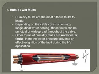
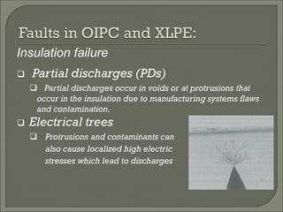
![ Paper or paper propylene
laminated (PPL) insulated with
individual metal sheaths and
impregnated with low pressure oil
It is estimated that about 83% of HV
cables in existing systems are paper
insulated [1].
At higher voltages they present
operational problems due to high
dielectric losses and presence of
voids.](https://image.slidesharecdn.com/power-cables-160211193139/85/Power-cables-16-320.jpg)
![ Paper insulation is still common, especially for land UG cables.
However, there is an increasing application of polymer cables
(XLPE),especially for in DC and submarine installations.
In polymer insulation the insulating XLPE compounds must act as
thermoplastic materials, be immune to thermal degradation and
must not be prone to defects such as voids ,contaminants [1].](https://image.slidesharecdn.com/power-cables-160211193139/85/Power-cables-18-320.jpg)
![ XLPE cables constitute about 2 - 5% of installed HV cable
capacity in the 115-161 kV range, and make up about 50 -
70% of new cable installations in the HV range(220KV and
more) [1].](https://image.slidesharecdn.com/power-cables-160211193139/85/Power-cables-19-320.jpg)