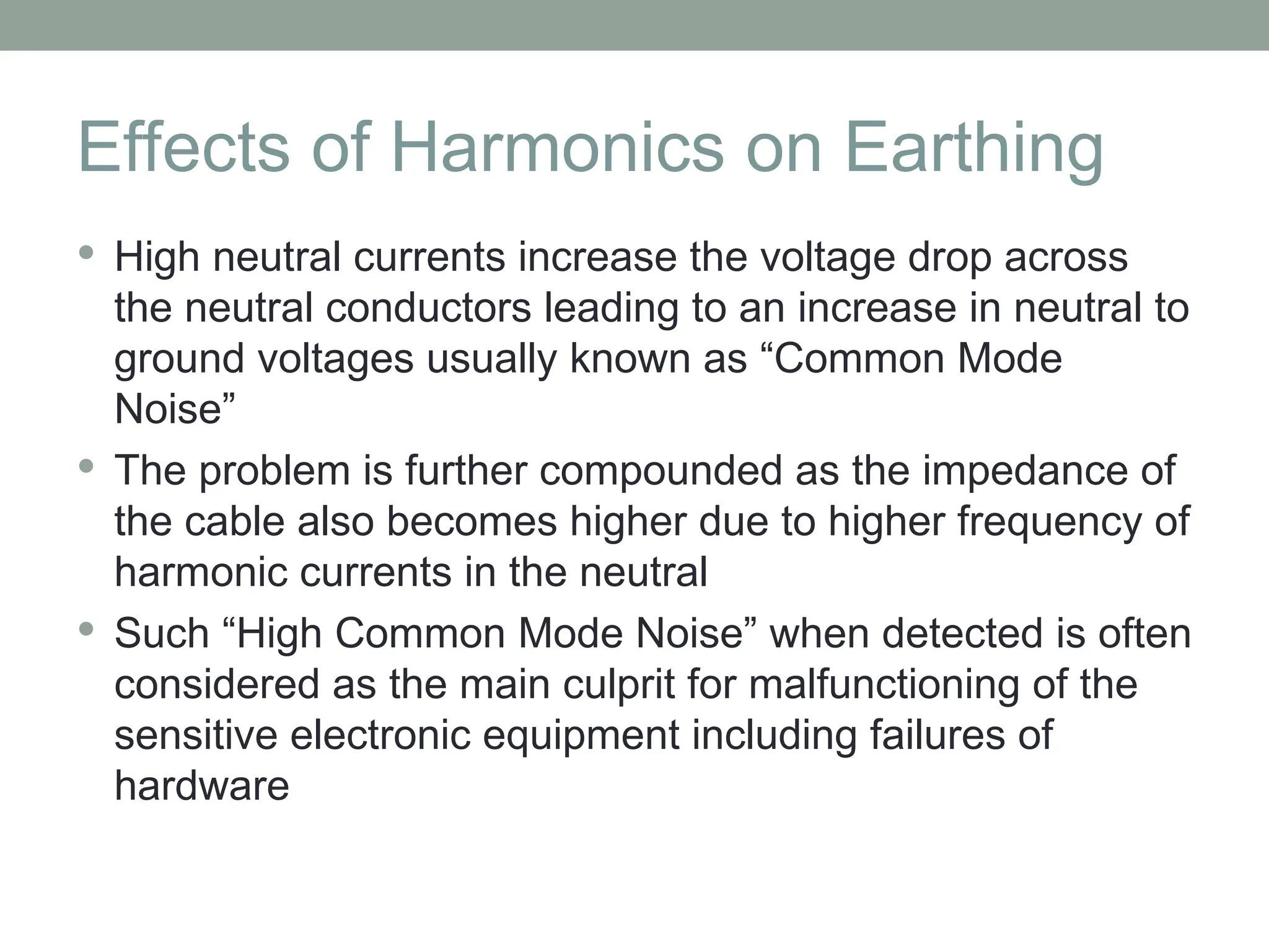
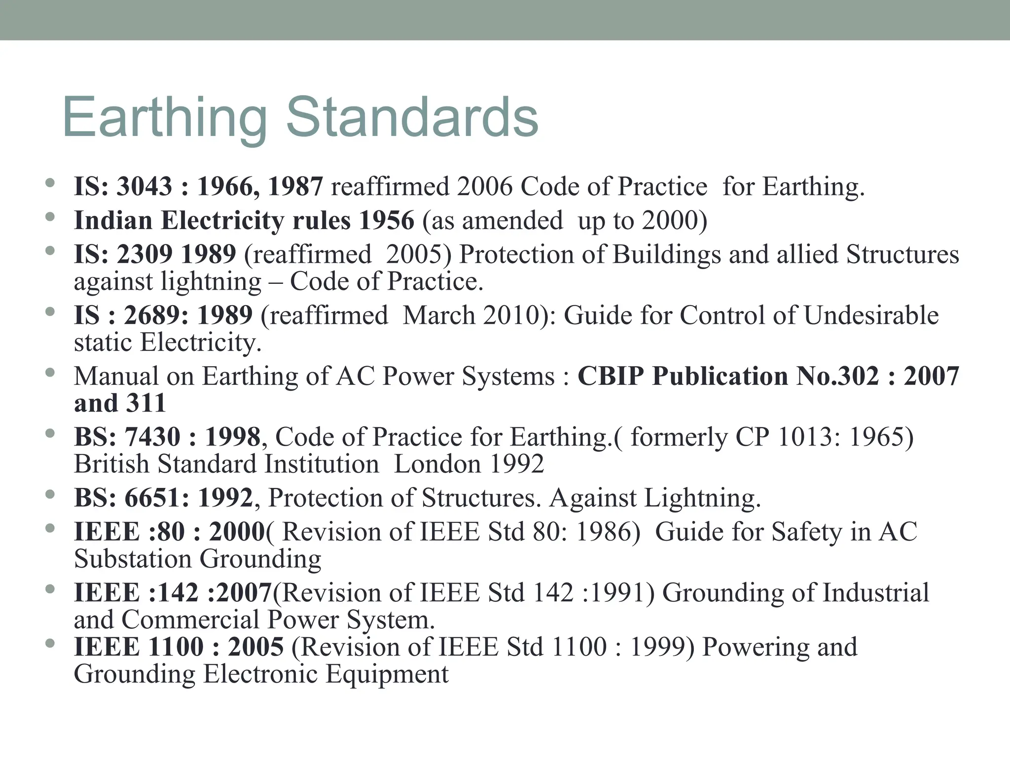
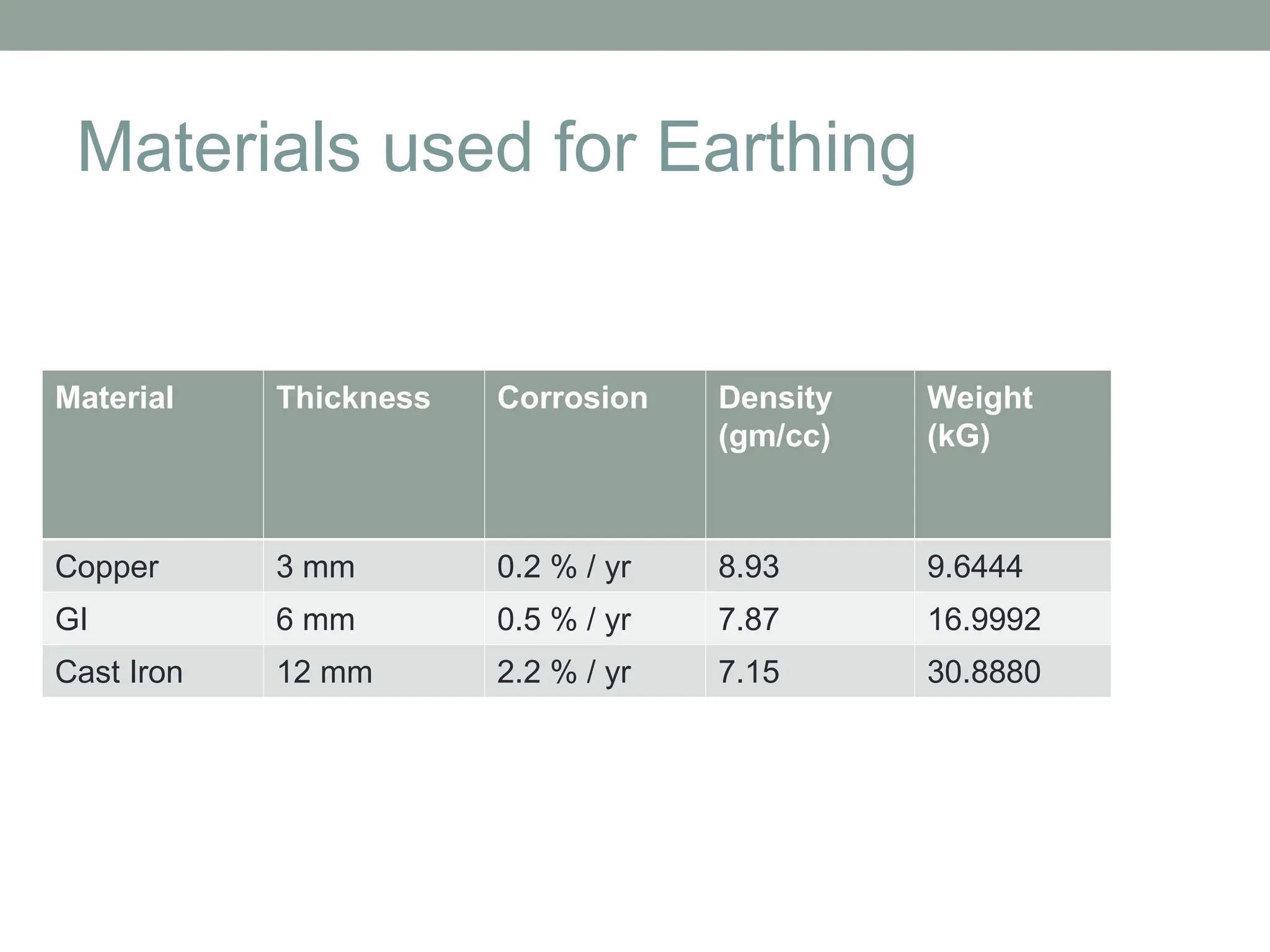
The document discusses the importance of earthing in power systems, highlighting its critical role in ensuring personal safety and protecting equipment from fault currents and lightning. It details various earthing methods, such as plate, pipe/rod, strip, and mat earthing, along with relevant standards and calculation methods for determining ground resistance. Furthermore, it emphasizes factors affecting soil resistivity and presents procedures for measuring soil resistivity in substation sites.


![Down Conductor
• Down conductor material
• Copper
• Galvanized Iron (GI)
Parameter Copper GI
Minimum Size 25 mm X 3 mm 50 mm X 6 mm
Initial Temperature 40 o
C
Final Temperature 395 o
C 500 o
C
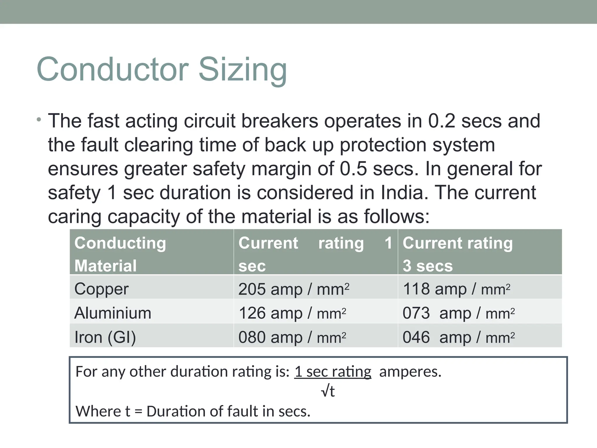
1 Sec Rating (Amp / Sq mm) 205 80
3 Sec Rating (Amp / Sq mm) 118 46
100 µs Rating
= Conductor size X
[(1 Sec rating) / √(100 µs) ]
(25 X 3 X 205) /
√(0.000100)]
= 1537.3 kA
(50 X 6 X 80) /
√(0.000100)]
= 2400 kA
Shape Shall be in the form of strip (flat) in order to
reduce the inductance](https://image.slidesharecdn.com/earthingsystempptsst-240806063149-612e3b23/75/EarthingSystem_PPT-sst-in-optcl-substation-ppt-9-2048.jpg)

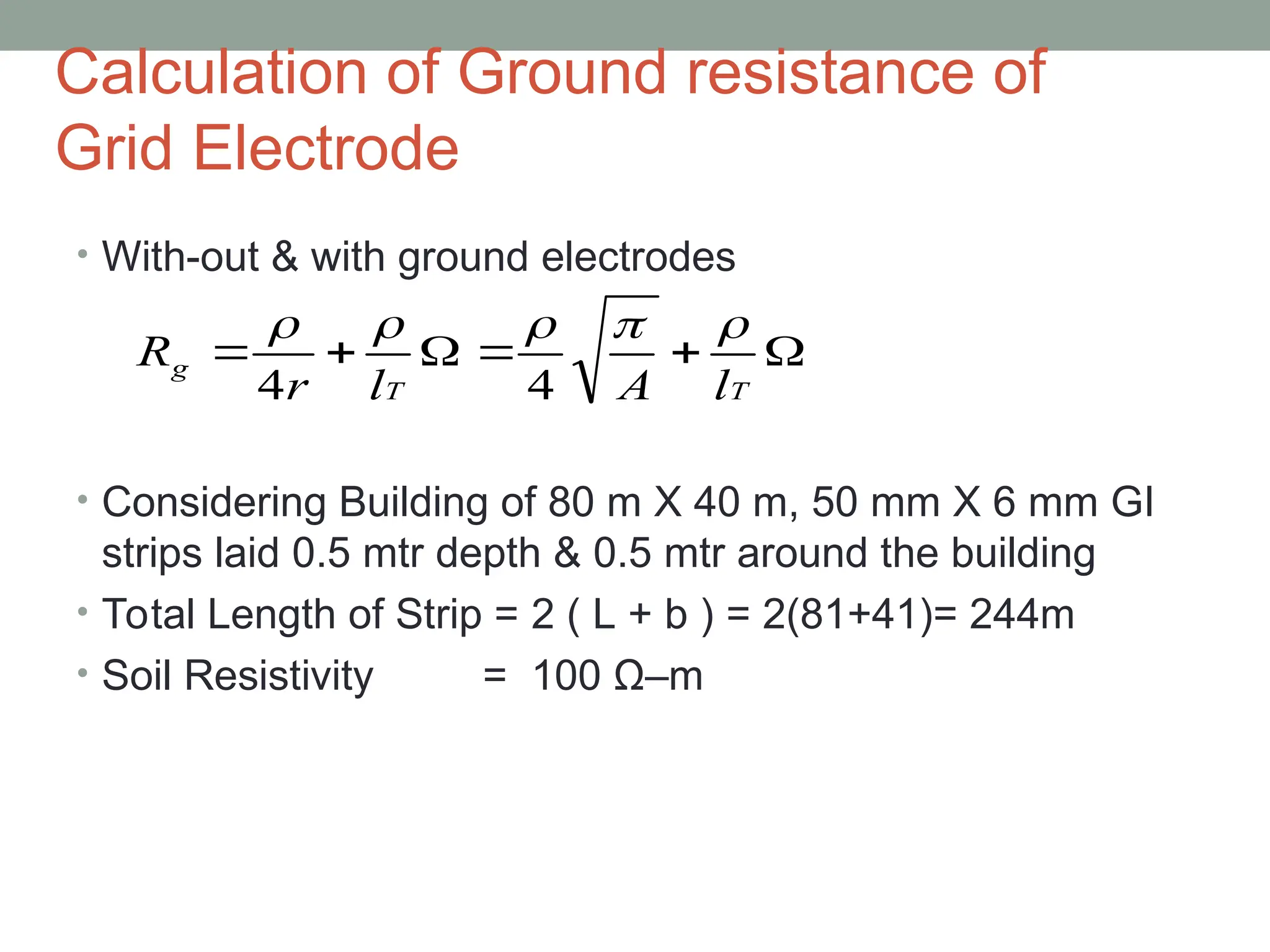
![Mat earthing
Is the combination of Strip & Rod earthing
Reference
IEEE 80 : 2000 Clause 14.2 ( 51) Page 64 (Laurent & Newmann)
IEEE 80 : 2000 Clause 14.2 ( 52) Page 65 (Sverak)
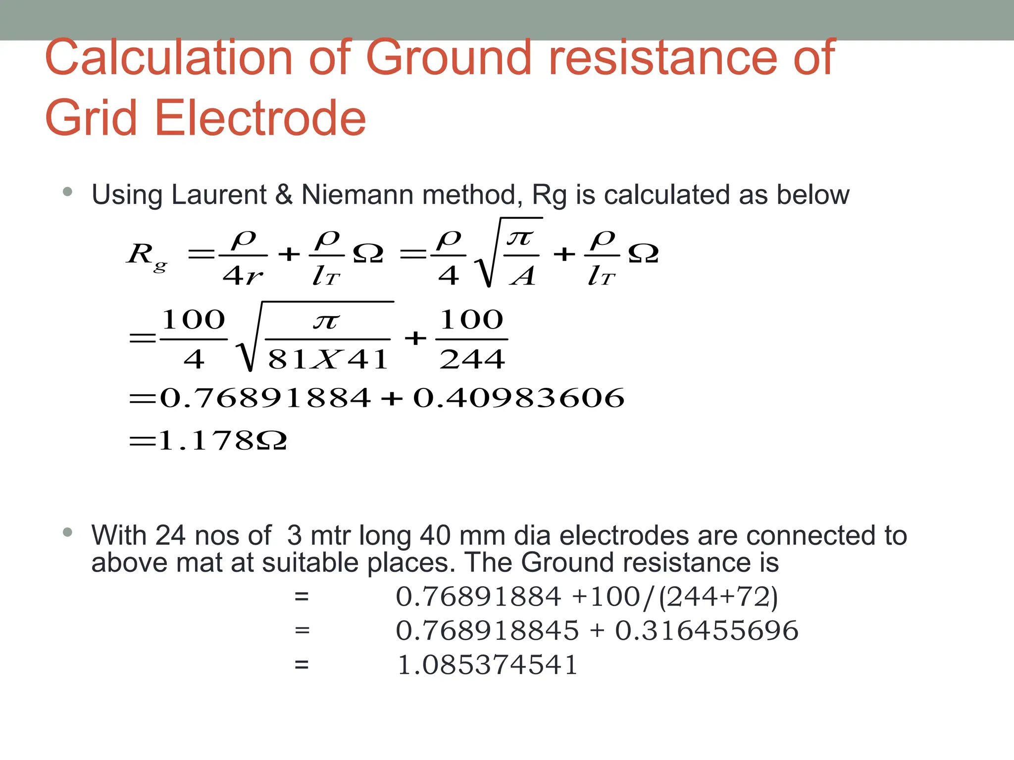
Earth resistance can be calculated using Laurent & Niemann
method as below
(OR)
Earth resistance can be calculated using Sverak method as below
T
T
g
l
A
l
r
R
4
4
)]
/
20
1
1
1
(
20
1
1
[
A
h
A
l
R
T
g
ρ = Resistivity of the soil (in ohm-m )
A = area of the station (in sq mtr)
lT = Total length of the conductor
(both strips & rods)
lt
A
Rg
443
.
0](https://image.slidesharecdn.com/earthingsystempptsst-240806063149-612e3b23/75/EarthingSystem_PPT-sst-in-optcl-substation-ppt-18-2048.jpg)
![Calculation of Ground resistance of
Grid Electrode
Using Sverak method, the earth resistance is calculated as below
With 24 nos of 3 mtr long 40 mm dia electrodes are connected to
above mat at suitable places. The Ground resistance is
= 100 [ 1/(244+72) + 0.00761540 ]
= 100 [0.010779956]
= 1.0779956
1.1713762
)
0.01171376
(
100
)
0.00761540
0.00409836
(
100
)]
41
81
/
20
5
.
0
1
1
1
(
41
81
20
1
244
1
[
100
)]
/
20
1
1
1
(
20
1
1
[
X
X
X
A
h
A
l
R
T
g ](https://image.slidesharecdn.com/earthingsystempptsst-240806063149-612e3b23/75/EarthingSystem_PPT-sst-in-optcl-substation-ppt-21-2048.jpg)