Download as PPSX, PPTX


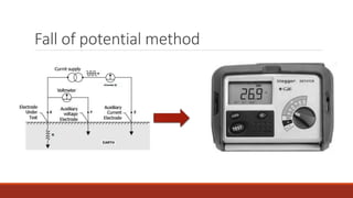
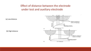
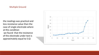
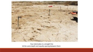
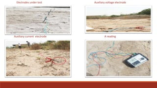


This document discusses methods for measuring ground resistance to ensure safe and effective grounding of electrical systems. It explains that ground resistance testing is important to verify a low-resistance path for fault currents. The most common method is the fall-of-potential test, which applies a known current through a test electrode and auxiliary electrode, then measures the voltage drop to calculate resistance. Proper spacing of electrodes is also important, as resistance readings are most accurate when the test and auxiliary electrodes are farther apart.


