This document provides an overview of central plant and specialty HVAC system design considerations. It outlines the course topics and instructors for a class on the subject. The document then discusses various central plant configurations including chilled water, condenser water, and thermal energy storage systems. It also provides examples of central plants for large campus systems and specialized facilities like the Bancroft Library archives building.
Cooling Optimization 101: A Beginner's Guide to Data Center CoolingUpsite Technologies
As new personnel enter the industry, they are often bombarded with a slew of buzz words and marketing messages that would lead them to believe that data centers almost run themselves. And while monitoring and DCIM solutions are improving the management of power and cooling, an understanding of the fundamental science is crucial to both see through the hype and get the most out of management systems. More so, as the veterans in our industry start to retire, much of the basic knowledge around power and cooling is often overlooked when training their successors. This session will provide that basic knowledge and give a fundamental understanding of the power and cooling infrastructure in a data center, with an emphasis on cooling optimization. In this session, you’ll learn how to recover stranded cooling capacity, reduce operating costs, improve IT equipment reliability, and prolong the life and capacity of the data center.
Gaining Data Center Cooling Efficiency Through Airflow ManagementUpsite Technologies
This presentation highlights research from Upsite Technologies regarding the latest best in data center airflow management and cooling, including steps to improvement. Originally delivered by Upsite President John Thornell at the AFCOM Boston-New England Chapter meeting.
PRINCIPAL OF COOLING TOWER
TYPES OF COOLING TOWER
DIFFERENT TERMS USED IN COOLING TOWER SPECIFICATION
AIR PROPERTIES AND
SIZING OF COOLING TOWER HEIGHT
TYPICAL SPECIFICATION FORMAT / DATASHEET
What is meant by “Airconditioning”?
Human Comfort
Why do we need A.C.?
Advantages and Disadvantage of A.C.
Ideal room temperature
some terminology-
Dry-bulb temperature
Wet-bulb temperature:
Dew point
Latent heat
Absolute humidity
Relative humidity
Specific humidity
Sensible heat
Evaporating Cooling
Condensation
Enthalpy
Entropy
7. Classification of air conditioners
8. Windows AC- advantages
Parts of the Window Air Conditioners
Working
The refrigeration system,
Air circulation system-room air cycle and
The hot air cycle.
Ventilation system,
Control system,
electrical protection system.
9.Split or Ductless AC-
Advantages, parts indoor and outdoor,
Types-
Wall mounted
Floor mounted/Tower AC
Ceiling mounted/Cassette AC
Multi Split ACs
10. Central Air Conditioning System
Advantages and disadvantages
11. Key differences between "Window", "Split" and a "cassette" air conditioners.
12. Cooling capacity
13. Energy Efficiency
14.Energy Consumption
15.Energy Efficiency Ratio
16.Energy Saving Methods
17.Some AC brands
Marco Piovan, Sales & Marketing HVAC Application Manager and Matteo Venturi, Sales & Marketing Application Specialist at Chillventa eSpecial 2020. NEW uChiller for process chiller and use of Chillbooster for condenser and liquid coolers for industrial applications.
Know more: carel.com/product/mchiller-process
When developing data center energy-use estimations, engineers must account for all sources of energy use in the facility. Most energy consumption is obvious: computers, cooling plant and related equipment, lighting, and other miscellaneous electrical loads. Designing efficient and effective data centers is a top priority for consulting engineers. Cooling is a large portion of data center energy use, second only to the IT load. Although there are several options to help maximize HVAC efficiency and minimize energy consumption, data centers come in many shapes, sizes, and configurations. By developing a deep understanding of their client’s data center HVAC requirements, consulting engineers can help maintain the necessary availability level of mission critical applications while reducing energy consumption.
Nereus for cooling - Sustainable Water Solutions, LLCdamiendasher
Sustainable Water Solutions, LLC is is a multi-discipline group of highly experienced and innovative water industry professionals who focus on providing the most complete, efficient and effective water reuse, water recycling, and process fluid treatment solutions available today.
Looking to save money on your hot water bills? Consider the free heat pump hot water rebate! Get cash back for installing an energy-efficient heat pump hot water system and enjoy long-term savings on your utility bills. Act now and take advantage of this valuable rebate offer. To get further details visit our website. www.timetosave.com.au
In latest years the use of waterloop systems in commercial refrigeration has seen a great boost thanks to the use of DC inverter driven compressors that have significantly improve the energy efficiency of this kind of systems.
The synergic use of DC inverter driven compressors and electronic expansion valves jointly managed by advanced control systems permit to combine the typical benefits of a waterloop system, such as factory tested plug and play cabinets, flexibility and charge/leaks reduction, with energy efficiency, food quality improvements, regulation stability and prehentive diagnostics.
CAREL is continuously improving its Heos sistema for DC waterloop systems, presenting how this technology can further improve the system analysis to a cabinet vs cabinet level, details not available with traditional systems, and how the benefits of this systems can be adapted using different refrigerants.
The Roman Empire A Historical Colossus.pdfkaushalkr1407
The Roman Empire, a vast and enduring power, stands as one of history's most remarkable civilizations, leaving an indelible imprint on the world. It emerged from the Roman Republic, transitioning into an imperial powerhouse under the leadership of Augustus Caesar in 27 BCE. This transformation marked the beginning of an era defined by unprecedented territorial expansion, architectural marvels, and profound cultural influence.
The empire's roots lie in the city of Rome, founded, according to legend, by Romulus in 753 BCE. Over centuries, Rome evolved from a small settlement to a formidable republic, characterized by a complex political system with elected officials and checks on power. However, internal strife, class conflicts, and military ambitions paved the way for the end of the Republic. Julius Caesar’s dictatorship and subsequent assassination in 44 BCE created a power vacuum, leading to a civil war. Octavian, later Augustus, emerged victorious, heralding the Roman Empire’s birth.
Under Augustus, the empire experienced the Pax Romana, a 200-year period of relative peace and stability. Augustus reformed the military, established efficient administrative systems, and initiated grand construction projects. The empire's borders expanded, encompassing territories from Britain to Egypt and from Spain to the Euphrates. Roman legions, renowned for their discipline and engineering prowess, secured and maintained these vast territories, building roads, fortifications, and cities that facilitated control and integration.
The Roman Empire’s society was hierarchical, with a rigid class system. At the top were the patricians, wealthy elites who held significant political power. Below them were the plebeians, free citizens with limited political influence, and the vast numbers of slaves who formed the backbone of the economy. The family unit was central, governed by the paterfamilias, the male head who held absolute authority.
Culturally, the Romans were eclectic, absorbing and adapting elements from the civilizations they encountered, particularly the Greeks. Roman art, literature, and philosophy reflected this synthesis, creating a rich cultural tapestry. Latin, the Roman language, became the lingua franca of the Western world, influencing numerous modern languages.
Roman architecture and engineering achievements were monumental. They perfected the arch, vault, and dome, constructing enduring structures like the Colosseum, Pantheon, and aqueducts. These engineering marvels not only showcased Roman ingenuity but also served practical purposes, from public entertainment to water supply.
Ethnobotany and Ethnopharmacology:
Ethnobotany in herbal drug evaluation,
Impact of Ethnobotany in traditional medicine,
New development in herbals,
Bio-prospecting tools for drug discovery,
Role of Ethnopharmacology in drug evaluation,
Reverse Pharmacology.
2024.06.01 Introducing a competency framework for languag learning materials ...Sandy Millin
http://sandymillin.wordpress.com/iateflwebinar2024
Published classroom materials form the basis of syllabuses, drive teacher professional development, and have a potentially huge influence on learners, teachers and education systems. All teachers also create their own materials, whether a few sentences on a blackboard, a highly-structured fully-realised online course, or anything in between. Despite this, the knowledge and skills needed to create effective language learning materials are rarely part of teacher training, and are mostly learnt by trial and error.
Knowledge and skills frameworks, generally called competency frameworks, for ELT teachers, trainers and managers have existed for a few years now. However, until I created one for my MA dissertation, there wasn’t one drawing together what we need to know and do to be able to effectively produce language learning materials.
This webinar will introduce you to my framework, highlighting the key competencies I identified from my research. It will also show how anybody involved in language teaching (any language, not just English!), teacher training, managing schools or developing language learning materials can benefit from using the framework.
Students, digital devices and success - Andreas Schleicher - 27 May 2024..pptxEduSkills OECD
Andreas Schleicher presents at the OECD webinar ‘Digital devices in schools: detrimental distraction or secret to success?’ on 27 May 2024. The presentation was based on findings from PISA 2022 results and the webinar helped launch the PISA in Focus ‘Managing screen time: How to protect and equip students against distraction’ https://www.oecd-ilibrary.org/education/managing-screen-time_7c225af4-en and the OECD Education Policy Perspective ‘Students, digital devices and success’ can be found here - https://oe.cd/il/5yV
Welcome to TechSoup New Member Orientation and Q&A (May 2024).pdfTechSoup
In this webinar you will learn how your organization can access TechSoup's wide variety of product discount and donation programs. From hardware to software, we'll give you a tour of the tools available to help your nonprofit with productivity, collaboration, financial management, donor tracking, security, and more.
Read| The latest issue of The Challenger is here! We are thrilled to announce that our school paper has qualified for the NATIONAL SCHOOLS PRESS CONFERENCE (NSPC) 2024. Thank you for your unwavering support and trust. Dive into the stories that made us stand out!
Synthetic Fiber Construction in lab .pptxPavel ( NSTU)
Synthetic fiber production is a fascinating and complex field that blends chemistry, engineering, and environmental science. By understanding these aspects, students can gain a comprehensive view of synthetic fiber production, its impact on society and the environment, and the potential for future innovations. Synthetic fibers play a crucial role in modern society, impacting various aspects of daily life, industry, and the environment. ynthetic fibers are integral to modern life, offering a range of benefits from cost-effectiveness and versatility to innovative applications and performance characteristics. While they pose environmental challenges, ongoing research and development aim to create more sustainable and eco-friendly alternatives. Understanding the importance of synthetic fibers helps in appreciating their role in the economy, industry, and daily life, while also emphasizing the need for sustainable practices and innovation.
Model Attribute Check Company Auto PropertyCeline George
In Odoo, the multi-company feature allows you to manage multiple companies within a single Odoo database instance. Each company can have its own configurations while still sharing common resources such as products, customers, and suppliers.
GIÁO ÁN DẠY THÊM (KẾ HOẠCH BÀI BUỔI 2) - TIẾNG ANH 8 GLOBAL SUCCESS (2 CỘT) N...
2015 x472 class 04 - central and specialty
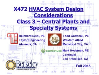
1. X472 HVAC System Design
Considerations
Class 3 – Central Plants and
Specialty Systems
Todd Gottshall, PE
Western Allied
Redwood City, CA
Reinhard Seidl, PE
Taylor Engineering
Alameda, CA
Fall 2015
Mark Hydeman, PE
Continual
San Francisco, CA
2. 2
General
Contact Information
Reinhard: rseidl@taylor-engineering.com
Mark: mhydeman@continual.net
Todd: tgottshall@westernallied.com
Text
• None
Slides
• download from web before class
• Log in to Box at https://app.box.com/login
• Username: x472student@gmail.com
• Password: x472_student (case sensitive)
3. 3
Course Outline
Date Class Topic Teacher
9/02/2015 1. Introduction / Systems Overview / walkthrough RS
9/09/2015 2. Generation Systems TG
9/16/2015 3. Distribution Systems RS
9/23/2015 4. Central Plants TG
9/30/2015 5. System Selection 1 - class exercises RS
10/07/2015 6. Specialty Building types (High rise, Lab, Hospital,
Data center)
TG
10/14/2015 7. System Selection 2 - class exercises RS
10/21/2015 8. Construction codes and Project delivery methods TG
10/28/2015 9. 2013 T24 and LEED v4 MH
11/04/2015 10. Life-Cycle Cost Analysis and exam hand-out TG
There are three instructors for this class. Todd Gottshall (TG), Reinhard Seidl (RS)
and Mark Hydeman (MH). The schedule below shows what topics will be covered by
who, and in what order.
4. 4
Birds Eye View of Systems
Single Story – tilt-up
• Single zone rooftop AC
• Split units, VRV
Two-Story
• Single zone rooftop AC
• Multi-zone rooftop AC
3-8 Story
• Centralized systems
• Dual Duct
• VAV RH
High-rise
• Floor-by-floor
• Built-up Systems
• Condenser loops, tenant heat
pumps
Campus Systems
• Central plant, airside/water
side economizers, thermal
energy storage
• Cogeneration
Specialty Systems
• Hotel
• Library
• Laboratory
• Data Center
• Underfloor
• Natural Ventilation
• Direct/Indirect
• Cascading cooling towers
Covered
last lesson
5. 5
Birds Eye View of Systems
Single Story – tilt-up
• Single zone rooftop AC
• Split units, VRV
Two-Story
• Single zone rooftop AC
• Multi-zone rooftop AC
3-8 Story
• Centralized systems
• Dual Duct
• VAV RH
High-rise
• Floor-by-floor
• Built-up Systems
• Condenser loops, tenant heat
pumps
Campus Systems
• Central plant, airside/water
side economizers, thermal
energy storage
• Cogeneration
Specialty Systems
• Hotel
• Library
• Laboratory
• Data Center
• Underfloor
• Natural Ventilation
• Direct/Indirect
• Cascading cooling towers
This lesson
12. 12
Central Plants
Old Paradigm
• Controls respond to changes in CHW temperature
• Variable flow causes low temperature trips, locks
out chiller, requires manual reset (may even
freeze)
• Maintain constant flow through chillers
New Paradigm
• Modern controls are robust and very responsive to
both flow and temperature variations
• Variable flow OK within range and rate-of-change
spec’d by chiller manufacturer
14. 14
Variable Flow Plant –
Chilled Water
Primary only, variable flow
system
COILS are now controlled
with 2-way valves, not 3-way
valves
CHILLER pump can “ride the
pump curve” or be equipped
with a variable speed drive to
vary flow.
15. 15
Variable Flow Plant –
Chilled Water
Multiple chillers,
headered pumps,
primary only,
variable flow
system
17. 17
Primary pump
Primary/Secondary Plant
Primary and
secondary pumps
de-couple the
chilled water flow
in the system
from the chilled
water flow in the
plant
Secondary
pump
Primary and
secondary pumps
de-couple the
chilled water flow
in the system
from the chilled
water flow in the
plant
Secondary
pump
Primary pump
Secondary
pump
ON
ON
100
gpm
100
gpm
100
gpm
ON
OFF
100
gpm
100
gpm
0 gpm
18. 18
Variable Flow Plant –
Chilled Water
Multiple chillers,
headered pumps,
primary/secondary,
variable flow
system
Primary pumps
Secondary
pumps
21. 21
Variable Flow Plant –
Chilled Water
Dedicated Pumping Advantages:
• Less control complexity
• Custom pump heads w/ unmatched chillers
• Usually less expensive
Headered Pumping Advantages:
• Better redundancy
• Valves can “soft load” chillers with primary-only
systems
• Easier to incorporate stand-by pump
22. 22
Variable Flow Plant –
Condenser Water
Dedicated Pumping Advantages:
• Less control complexity
• Custom pump heads w/ unmatched chillers
• Usually less expensive
Headered Pumping Advantages:
• Better redundancy
• Valves can double as head pressure control
• Easier to incorporate stand-by pump
• Can operate fewer CW pumps than chillers
Isolation
valve for low
flow – avoid
by using low-
flow options
on towers
23. 23
Low dT – primary only
system
Low load but excessively open valves – high flow,
low dT – problem originates on the use side, not on
the plant side
Becomes a problem on the plant side – have to run
multiple chillers to generate sufficient flow – now
running multiple chillers at low load, inefficiently
24. 24
“Death spiral” –
primary/secondary
As before, problem with coils results in high
flow on building side and low dT, and high
secondary pump speed
Primary
pumps
Secondary
pumps
Unless the primary pumps are sped up, CHWR (warm) now goes
through the bypass backward, and gets into the CHWS, heating it
up, and thus forcing valves even more open / secondary pumps
to even higher speed
Indepth Article:
http://www.taylor-
engineering.com/downloads/articles/ASHRAE%20Symposium%2
0AC-02-6-1%20Degrading%20Delta-T-Taylor.pdf
25. 25
Lower First Costs
Less Plant Space Required
Reduced Pump HP
• Reduced pressure drop due to fewer pump
connections, less piping
• Higher efficiency pumps (unless more expensive
reduced speed pumps used on primary side)
Lower Pump Energy
• Reduced connected HP
• “Cube Law” savings due to VFD and variable flow
through both primary and secondary circuit
Advantages of Primary-only Vs.
Primary/Secondary
26. 26
Use Primary-only Systems for:
• Plants with many chillers (more than three) and
with fairly high base loads where the need for
bypass is minimal or nil and flow fluctuations
during staging are small due to the large number of
chillers; and
• Plants where design engineers and future on-site
operators understand the complexity of the
controls and the need to maintain them.
Otherwise Use Primary-secondary
Primary-only Vs.
Primary/secondary
27. 27
UC Merced – Large Scale
Energy Efficiency
500,000 sq.ft., growing
LEED Gold Campus
Comprehensive Controls and
Commissioning including Central
Plant
Classroom Building, Health and
Wellness Center, Sierra Terraces
Housing, Dining Center
31. 31
Birds Eye View of Systems
Single Story – tilt-up
• Single zone rooftop AC
• Split units, VRV
Two-Story
• Single zone rooftop AC
• Multi-zone rooftop AC
3-8 Story
• Centralized systems
• Dual Duct
• VAV RH
High-rise
• Floor-by-floor
• Built-up Systems
• Condenser loops, tenant heat
pumps
Campus Systems
• Central plant, airside/water
side economizers, thermal
energy storage
• Cogeneration
Specialty Systems
• Hotel
• Library
• Laboratory
• Underfloor
• Natural Ventilation
• Direct/Indirect
• Cascading cooling towers
36. 36
Birds Eye View of Systems
Single Story – tilt-up
• Single zone rooftop AC
• Split units, VRV
Two-Story
• Single zone rooftop AC
• Multi-zone rooftop AC
3-8 Story
• Centralized systems
• Dual Duct
• VAV RH
High-rise
• Floor-by-floor
• Built-up Systems
• Condenser loops, tenant heat
pumps
Campus Systems
• Central plant, airside/water
side economizers, thermal
energy storage
• Cogeneration
Specialty Systems
• Hotel
• Library (Bancroft)
• Laboratory
• Data Center
• Underfloor
• Natural Ventilation
• Direct/Indirect
• Cascading cooling towers
38. 38
Bancroft Library
Multiple systems serving different
portions of the building with
different environmental criteria
Full size duct diagram: See Bancroft Iso.pdf
40. 40
Bancroft: Base HVAC
Systems
Two water-cooled screw chillers – 120
tons each
Design chilled water temperature = 39oF
Class A System criteria: 60oF, 40% RH =
36oF DP
Cannot adequately dehumidify with
Chilled Water
41. 41
Desiccant Dehumidification
The outdoor air (OA) point on the chart is shown at the dehumidification design conditions described in
section 2.6.3 above. OA is cooled with the pre-cooling coil to a dry-bulb (DB) temperature of 45°F. With
39°F CHW this is an achievable temperature.
The resulting point is labeled OA-cooled on the chart.
The cooled OA is now run through the desiccant dehumidification wheel and dried/heated. The chart
shows this as an adiabatic process where the moisture level goes down and the DB temperature goes
up. Air leaving the desiccant wheel is at the point labeled OA-dry.
Some of the cooled OA is bypassed around the desiccant wheel and some goes through
the wheel. After the wheel, the bypassed air and dried air is mixed. Design ratio is 2400
cfm through the wheel and 2600 cfm bypassed. Resulting mixed air condition is at point
OA-mix.
This OA-mix air is then mixed with the return air from the Class A spaces. Design
quantities are 4000 cfm OA-mix and 19,500 cfm return air. Resulting condition is labeled
The mixed air would then be cooled with the
cooling coil to down to the required supply
air temperature (SAT) of 54.8°F. This is
point “SA” on the chart. The cooling process
is not shown. This would be sensible cooling
only.
“Mix” on the chart. This mixed air has a DP of 36°F, which is below the
37°F DP required to make the Class A spaces the required relative
humidity. Actual quantity of air that is bypassed around the desiccant
wheel will be modulated by the control system. to achieve the correct
supply air dew point, but this chart shows we have adequate capacity for
the design scenario.
Outdoor air
cooled to 45°F
With CHW
Outdoor dried
w desiccant
unit
Mixed w
return air
Cooled to final supply
temp with CHW
1
2
3
4
43. 43
The “B” systems serve the archive areas of the building where active research is occurring. The relative
humidity requirements of these areas are the same as the “A” areas, but the temperatures are warmer
to allow more comfortable conditions for researchers. The Class B air handling system consists of 2 air
handling units, AH-B1 and AH-B2.
AH-B1 delivers cold, dry air to the zones while AH-B2 delivers “neutral” (70 °F temperature) humid air
to the zones. AH-B2 is essentially a large humidifier for the entire building. The Class B spaces require
both temperature and humidity control. Cold dry air from AH-B1 is mixed with neutral humid air from
AH-B2 and then a reheat coil is provided in each zone to be able to achieve the required space
conditions.
COOLING: The cold deck with air coming from AH-B1 is shown at the
lower left, with some heat gain from fan and duct. The air is reheated for
temperature control and mixed with neutral deck air for humidity control.
This scheme allows zones to be individually controlled for
both temperature and humidity, without the more typical
approach of using individual humidifiers per zone.
Humidity/Temp control w. dual
duct
From cold deck AHU, reheated to
move the “Cold VAV Reheat”
point left or right on the chart, and
thus change the slope of the
mixing line.
1
Air warms up in room to go from
“VAV mix” at 58°F / 65%RH to
“Room mix” at 72°F / 43% RH
3
Air from neutral deck AHU is essentially
like laundry exhaust – warm and very
humid, at about 72°F / 50% RH
2
44. 44
HEATING: The cold deck with air coming from AH-B1 is shown at the
lower left, with some heat gain from fan and duct. The air is now
significantly reheated for temperature control and mixed with neutral
deck air for humidity control.
This scheme allows zones to be individually controlled for
both temperature and humidity, without the more typical
approach of using individual humidifiers per zone.
Humidity/Temp control w. dual
duct
In addition to fan and duct heat
gain, reheat (HW) is added to get
to correct leaving air temp (much
like typical VAV RH)
1
Neutral deck air mixed
in to control humidity
2
The “B” systems serve the archive areas of the building where active research is occurring. The relative humidity requirements of these areas are the same as the
“A” areas, but the temperatures are warmer to allow more comfortable conditions for researchers. The Class B air handling system consists of 2 air handling units,
AH-B1 and AH-B2.
AH-B1 delivers cold, dry air to the zones while AH-B2 delivers “neutral” (70 °F temperature) humid air to the zones. AH-B2 is essentially a large humidifier for the
entire building. The Class B spaces require both temperature and humidity control. Cold dry air from AH-B1 is mixed with neutral humid air from AH-B2 and then a
reheat coil is provided in each zone to be able to achieve the required space conditions.
Room cools air w slight
addition of moisture
3
45. 45
Birds Eye View of Systems
Single Story – tilt-up
• Single zone rooftop AC
• Split units, VRV
Two-Story
• Single zone rooftop AC
• Multi-zone rooftop AC
3-8 Story
• Centralized systems
• Dual Duct
• VAV RH
High-rise
• Floor-by-floor
• Built-up Systems
• Condenser loops, tenant heat
pumps
Campus Systems
• Central plant, airside/water
side economizers, thermal
energy storage
• Cogeneration
Specialty Systems
• Hotel
• Library
• Laboratory
• Data Center
• Underfloor
• Natural Ventilation
• Direct/Indirect
• Cascading cooling towers
50. 50
Hospitals and Laboratories
Both need pressure control
• Hospital: infection control
• Lab: infection / toxic / flammable control
Historically, constant volume systems
used to ensure pressure control
Big reheat penalty for fluctuating loads
T24-2013 Section 140.9c has prescriptive
requirement for VAV supply/exhaust
51. 51
Hospitals and Laboratories
Low load Low Load High load Low load
A B C D
Constant volume system means easy pressure control (which is a plus)
But: the supply air temperature from the air handler has to be low
enough to handle the room with the highest load (room C). Since the
other rooms have low loads, they all have to reheat (their full design air
flow) to maintain temperature.
Some reheat ($$)Big reheat ($$$) Big reheat ($$$)
52. 52
Hospitals and Laboratories
Ways around this energy penalty
• VAV lab:
Tracking VAV controls: one VAV zone makes up air, one exhausts air, CFM on
hood monitored by air valve position or fume hood face velocity monitor with
sash sensor, or exhaust duct airflow sensors
Pressure control: hoods take what they need, supply maintains load and min
ACH, exhaust maintains room pressure
Adaptive control: combination of the two above, where room pressure sensor
resets cfm differential between supply and exhaust
• Zone coils: install heating and cooling coils at the zone level, so there is
no reheat penalty
• Dual duct system with mixing operation: maintain constant airflow with
neutral air (from hot deck) mixed with cooling air
• Active chilled beams – is essentially little different than zone coils: means
installing zone level temperature controls with DOAS upgraded to
maintain pressurization minimums. In theory, this is more efficient than
zone coils because of reduced pressure drop.
54. 54
Hospitals and Laboratories
Zone coils:
• Expensive solution
• Requires lots of piping and adds pressure
drop to central system unless fan-powered
terminals are used, or terminal units such
as fancoils or induction units
• But: gets rid of potentially high reheat
energy cost which is driven by high air
volumes
55. 55
Hospitals and Laboratories
Dual Duct:
• Less expensive solution than zone coils
• Requires a good floor plate as interior with
spaces like offices or general purpose
rooms – this provides neutral (return) air
that can be used for mixing high-minimum
rooms such as labs.
• For buildings with lots of exterior spaces, or
buildings with mostly lab spaces, this
system offers little advantage because of
large outside air requirements.
56. 56
Hospitals and Laboratories
Chilled beams:
• Works for load driven rooms, if the actual loads are higher
than the minimum airflow requirements or hood
requirements already cover (for air-change or hood driven
rooms).
• Only difference to zone coils is that the chilled beam
operates without condensation, so that a wet surface
(prohibited in some hospital applications, for cleanliness)
is prevented.
• However, the same thing can be achieved with terminal
coils running warmer water, will have more Btu/h for same
coil because of higher airflow through coil (not just
induced)
57. 57
Control methods
Pressure tracking
• Cheapest. Hoods and terminals don’t need to communicate. Hood “does its
own thing” and exhaust simply trims room pressure.
• Disadvantage: when a door is opened, pressure cannot be maintained, and
terminals either go haywire or are limited to begin with in their range. Slowing
reaction of system helps combat doors opening and closing, but then makes
control less effective
Volume or Flow tracking
• Always “keeps its cool” regardless of envelope / door changes, maintains a
steady offset
• Disadvantage: More expensive, does not actually check room pressure
which is the original driver for the whole mechanism
Adaptive offset (both pressure and volume tracking)
• Most expensive
• Offset between supply and return is reset by pressure readings, giving the
best of both worlds – fast, steady operation AND actual pressure control
58. 58
Laboratories
With hoods, typically 3 elements involved: Hood, Supply, and general exhaust. In
VAV hood application, all three have controllers. For critical applications, all three
will be fast acting.
60. 60
1. Pressure tracking
Hood just looks at its own exhaust
(typ. with face velocity monitor).
Only hood velocity matters, the
exhaust volume “is what it is”
1
Supply valve satisfies 2 conditions:
A. Heat load (with thermostat)
B. Airflow minimum, either
1. Air change minimum (set by
designer or owner, code)
2. or CFM/sqft
2
3 Exhaust valve
modulates to maintain
room pressure
61. 61
2. Flow tracking
Now calculates airflow (either with
hood velocity and sash position,
or with flow sensor in exhaust)
1
Supply valve satisfies 2 conditions:
A. Heat load (with thermostat)
B. Airflow minimum, either
1. Air change minimum (set by
designer or owner, code)
2. or CFM/sqft
2
3 Exhaust valve
modulates to maintain
airflow offset by
subtracting hood
exhaust from makeup,
and then exhausting a
little bit more than the
result to get a
negative room
62. 62
3. Adaptive offset
Supply valve satisfies 2 conditions:
A. Heat load (with thermostat)
B. Airflow minimum, either
1. Air change minimum (set by
designer or owner, code)
2. or CFM/sqft
2
3 Exhaust valve
modulates to maintain
airflow offset by
subtracting hood
exhaust from makeup,
and then exhausting a
little bit more than
the result to get a
negative room
PLUS: the “little bit
more” differential
keeps getting reset to
new values to ensure
that the room pressure
is actually doing what
we want
63. 63
Hospitals and Laboratories
Pressure-based VAV Tracking
• Pressure control: hoods take what they need, supply VAV
maintains load and min ACH, exhaust VAV maintains room
pressure
No hood cfm monitoring required, although hood volume still
modulates (sash position or face velocity monitor)
• Low pressures (0.03”-0.05”). Can be done with “through the wall”
hot-wire sensors or pressure transducers without flow across
wall.
• Disadvantage: hard to tune correctly to ignore doors opening
(no reaction wanted even though pressures will swing wildly).
Typically more expensive
• Advantage: better feedback on actual operation.
64. 64
Hospitals and Laboratories
Airflow Tracking VAV
• Tracking VAV controls: Hoods take what they need, one VAV terminal
makes up air for loads and min. ACH, one terminal exhausts air to
maintain overall CFM differential. CFM on hood monitored by
Air valve position or
Fume hood face velocity monitor and sash sensor or
Exhaust duct airflow sensor
• Either differential (i.e. maintain 100 cfm negative per door)
• Or ratio (i.e. maintain exhaust at 110% of supply)
• Disadvantage: no real feedback on how well system works to maintain
room pressure (typ. = lab negative with respect to corridor). No check
on whether balance is maintained over time
• Advantage: (less) expensive and stable
65. 65
Hospitals and Laboratories
Adaptive offset control
• Basic control loop uses airflow tracking
• The airflow differential may not be correct after some time (think 1-2
years) because of changes in leakage rate in the envelope (door
frames warp, holes drilled for wiring, conduit) or in the short term
because a door opens
• Pressure sensor then used to update the airflow differential at slower
loop speed than airflow tracking, to reset differential for what is
required to maintain room pressure
• The reset mechanism can be slow to avoid unstable controls, but
airflow control can be fast
• Disadvantage: Most expensive option (combines all sensors from
both underlying control methods)
• Advantage: best stability and performance.
67. 67
Hospitals and Laboratories
Hood exhaust valves can be a venturi-type valves that are self-balancing (like griswold flow
controllers) to their setpoint, and can be actuated without a flow sensor (to prevent
corrosion of sensor)
Other air valves use vortex shedding sensors in lieu of pitot-style flow crosses and fast
actuators to maintain airflow. Benefits are that the airflow can be reset via the control
system.
Spring-loaded venturi
damper maintains a pre-
defined cfm flow rater over
wide pressure range when
actuator is set to a certain
setting. Example: 40%
open actuator means 840
cfm, regardless of duct and
room pressure
Used without actuator for
constant volume hood
systems. No flow cross.
Actuated Dampers and
Fast Control Algorithms
adjust the airflow to Airflow
Setpoint from the DDC.
Airflow can be set by
Space Load, ACH
Requirements, or Pressure
Offset. Can be used on
Supply and Exhaust
Butterfly Dampers without
flow sensing can be used
with hood face velocity
sensors.
68. 68
Birds Eye View of Systems
Single Story – tilt-up
• Single zone rooftop AC
• Split units, VRV
Two-Story
• Single zone rooftop AC
• Multi-zone rooftop AC
3-8 Story
• Centralized systems
• Dual Duct
• VAV RH
High-rise
• Floor-by-floor
• Built-up Systems
• Condenser loops, tenant heat
pumps
Campus Systems
• Central plant, airside/water
side economizers, thermal
energy storage
• Cogeneration
Specialty Systems
• Hotel
• Library
• Laboratory
• Data Center
• Underfloor
• Natural Ventilation
• Direct/Indirect
• Cascading cooling towers
69. 69
Data Centers
History:
• Started off with all PC’s crammed into one room, then rack mounted
• As more racks were added, first more house air and then ceiling splits or
fancoils were added.
• When that failed to work, dedicated large splits or fancoils
(CRACs=computer room air conditioning unit or CRAHs=computer room
air handlers) were developed and added.
• With ongoing problems and hot spots, underfloor distribution gained
acceptance followed by hot-aisle/cold aisle configuration
• With larger densities still, additional fancoils on top of racks, in line with
racks or on the rear of racks (heat exchangers) are now coming onto the
market.
• In combination with these, capped aisles (hot or cold) are also being
added (This is now a Prescriptive requirement for rooms larger than
175KW.)
70. 70
Data Centers
Slides from NREL Presentation, 2015
Data Center Efficiency Metric
Power Usage Effectiveness (PUE)
76. 76
Data Centers
Step 5: more load
Large scale dedicated facilities with perimeter CRAC/CRAH
Underfloor distribution with hot aisle/cold aisle setup in racks
77. 77
Data Centers
Step 6a: more load
Fewer CRACs/CRAHs (base load, dehum., filtration)
Overhead fancoils for added cooling density
78. 78
Data Centers
Step 6a: more load
Fewer CRACs/CRAHs (base load, dehum., filtration)
Overhead fancoils for added cooling density
79. 79
Data Centers
Step 6b: more load
Fewer CRACs/CRAHs (base load, dehum., filtration)
In-row fancoils for more direct cooling
80. 80
Data Centers
Step 6b: more load
Fewer CRACs/CRAHs (base load, dehum., filtration)
In-row fancoils for more direct cooling
Capped cold aisles for better air flow management
81. 81
Data Centers
Step 6b: more load
Fewer CRACs/CRAHs (base load, dehum., filtration)
In-row fancoils for more direct cooling
Capped hot aisles for better airflow mgmt – note return duct
82. 82
Data Centers
Step 6c: more load
More CRACs/CRAHs (base load, dehum., filtration)
Rear door heat exchangers leave entire room neutral
85. 85
Data Centers
Elimination of chiller plant
• Higher overall temperatures make cooling without chillers
a possibility,
• Typical arrangement with chilled water shown below
95°/66°
55°42° CHW
75° CW
85° CW
55° CHW
86. 86
Data Centers
Elimination of chiller plant
• Higher overall temperatures make cooling without chillers
a possibility
• Alternate arrangement shown below, uses a coil with CW
in the AHU
85°
75° CW
85° CW
95°/66°
87. 87
Data Centers
Elimination of chiller plant
• Higher overall temperatures make cooling without chillers
a possibility
• “Insert” cooling tower into AHU as it were (swamp cooler,
Indirect Evaporative Cooling)
68°
95°/66°
88. 88
Data Centers
Elimination of chiller plant
• Higher overall temperatures make cooling without chillers
a possibility
• “Insert” cooling tower into AHU as it were (swamp cooler,
Indirect Evaporative Cooling)
• Slide from ASHRAE Journal March 2015 Article
89. 89
Data Centers
Elimination of chiller plant
• Higher overall temperatures make cooling without chillers
a possibility
• Also possible: dry plate air-to-air HX in AHU, with swamp
cooler on scavenger air side
• Slide again from March 2015 ASHRAE Journal
90. 90
Data Centers
Elimination of chiller plant
• Also possible for rear doors when load density per rack not
too high (~ 10kW/rack or so)
70° CW possible in Bay Area
w 66°F design wet bulb
85° CW
78°78° 100°
Example: 600 gpm, 85°->70°F tower, 375 tons
30 Hp fan, 20’ L x 10’ W x 12’ H
91. 91
Birds Eye View of Systems
Single Story – tilt-up
• Single zone rooftop AC
• Split units, VRV
Two-Story
• Single zone rooftop AC
• Multi-zone rooftop AC
3-8 Story
• Centralized systems
• Dual Duct
• VAV RH
High-rise
• Floor-by-floor
• Built-up Systems
• Condenser loops, tenant heat
pumps
Campus Systems
• Central plant, airside/water
side economizers, thermal
energy storage
• Cogeneration
Specialty Systems
• Hotel
• Library
• Laboratory
• Underfloor
• Natural Ventilation
• Direct/Indirect
• Cascading cooling towers
92. 92
Multi-stage towers
Not common, but in theory allow cooling tower system to
produce water at wetbulb of surrounding air (note – very
similar principle as used in the Coolerado cooler)
Direct 2-stage
83F DB,
62F WB
93. 93
Multi-stage towers
Not common, but in theory allow cooling tower system to
produce “chilled” water at or lower than the wetbulb of
surrounding air
Indirect 2-stage
83F DB,
63F WB
94. 94
Data Centers
Elimination of chiller plant
• Title-24 2013 Requires Economizers on Computer Rooms over
20 Watts / SF. Eliminates the “Process Load” Exception
• Can be incorporated with Direct Evaporative Cooling
• Additive Energy Conservation Measure: Use waste heat to heat
adjacent Office spaces
Hydeman, 2012
95. 95
Data Centers
Step 8: more load
• On-Board liquid cooling
• See http://hightech.lbl.gov/training/modules/08-liquid-
cooling.pdf
• and
http://datacenterpulse.org/The
ChillOff
96. 96
Birds Eye View of Systems
Single Story – tilt-up
• Single zone rooftop AC
• Split units, VRV
Two-Story
• Single zone rooftop AC
• Multi-zone rooftop AC
3-8 Story
• Centralized systems
• Dual Duct
• VAV RH
High-rise
• Floor-by-floor
• Built-up Systems
• Condenser loops, tenant heat
pumps
Campus Systems
• Central plant, airside/water
side economizers, thermal
energy storage
• Cogeneration
Specialty Systems
• Hotel
• Library
• Laboratory
• Underfloor
• Natural Ventilation
• Direct/Indirect
• Cascading cooling towers