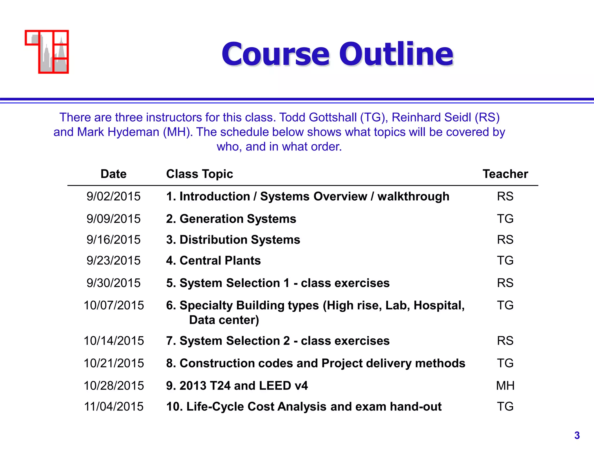
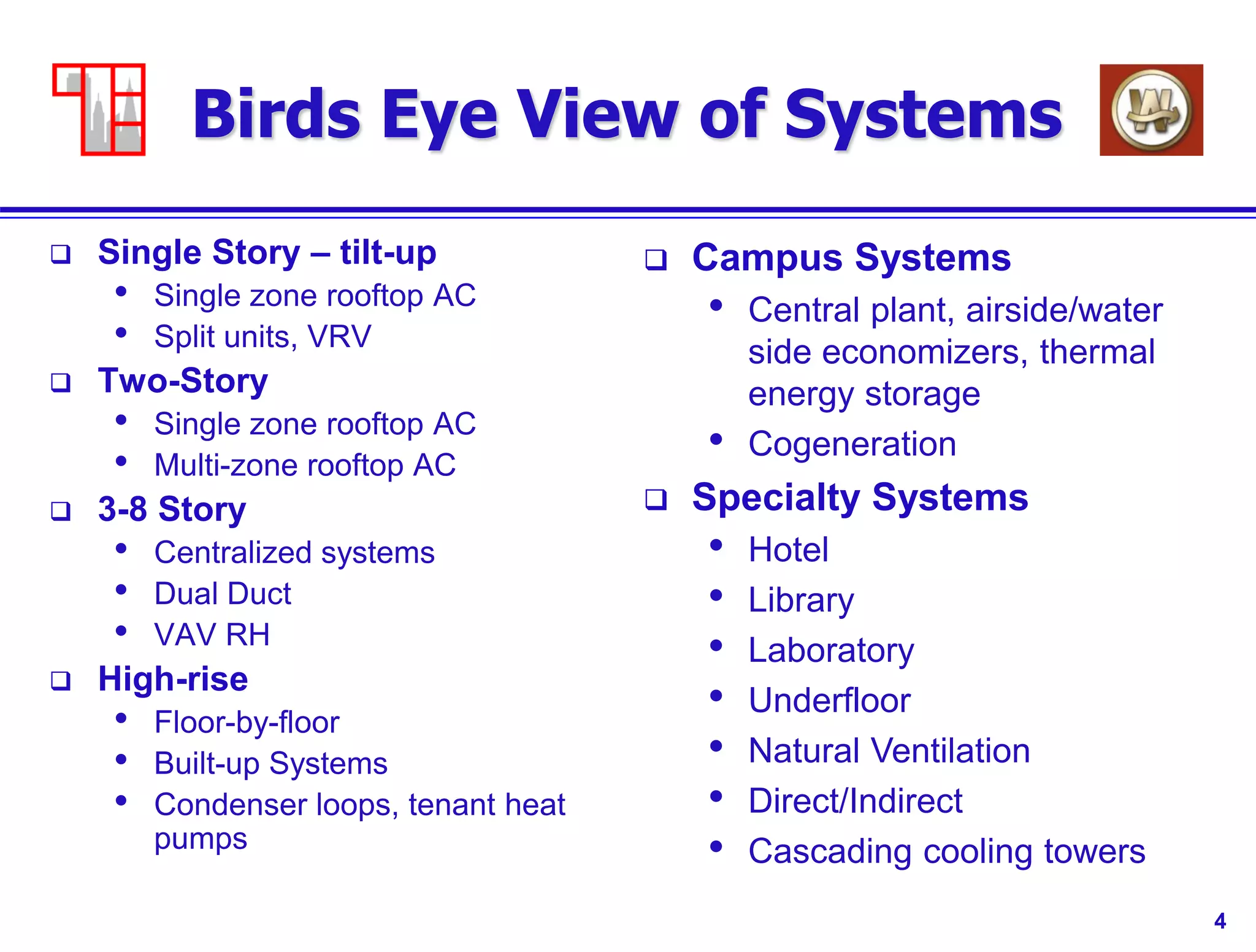
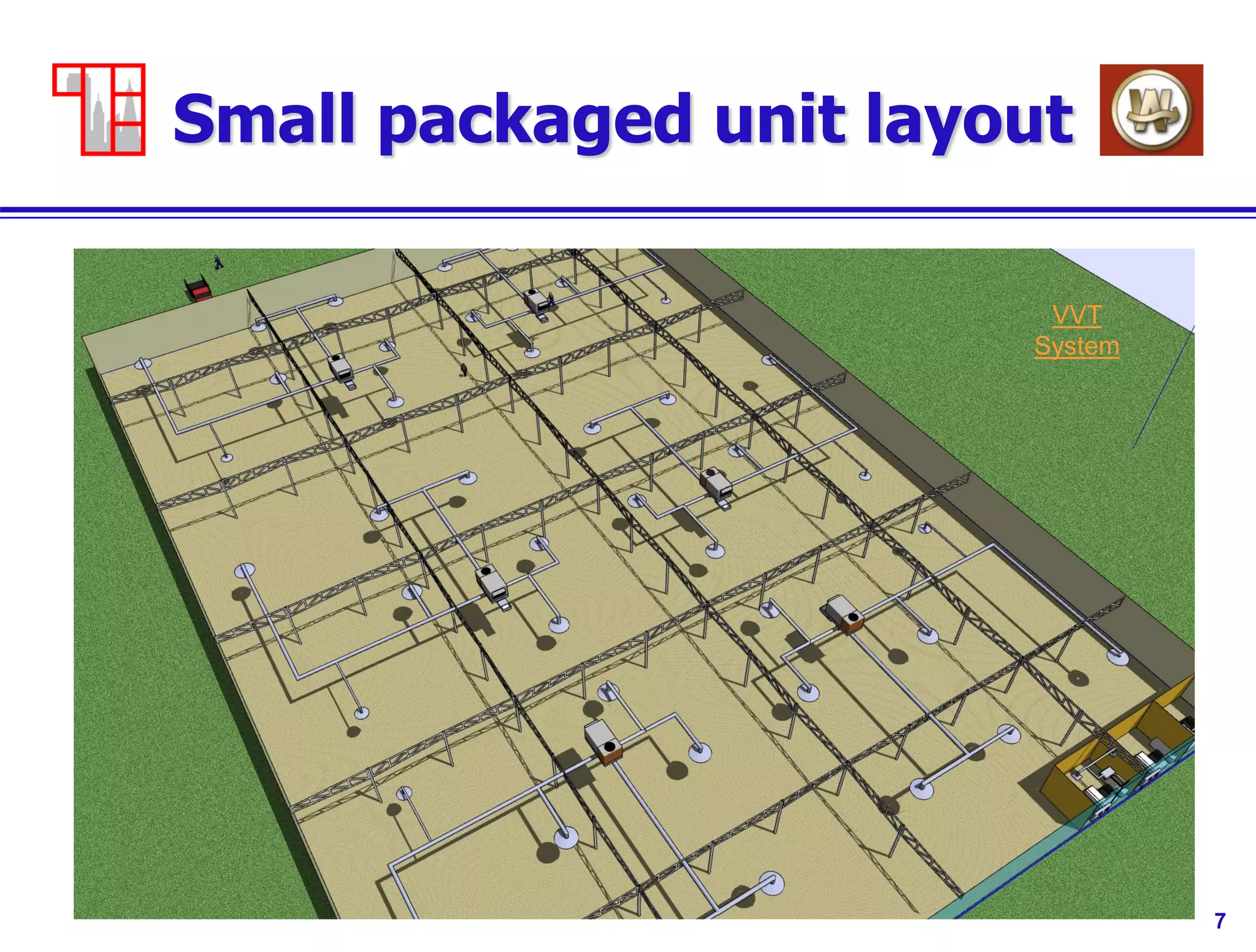
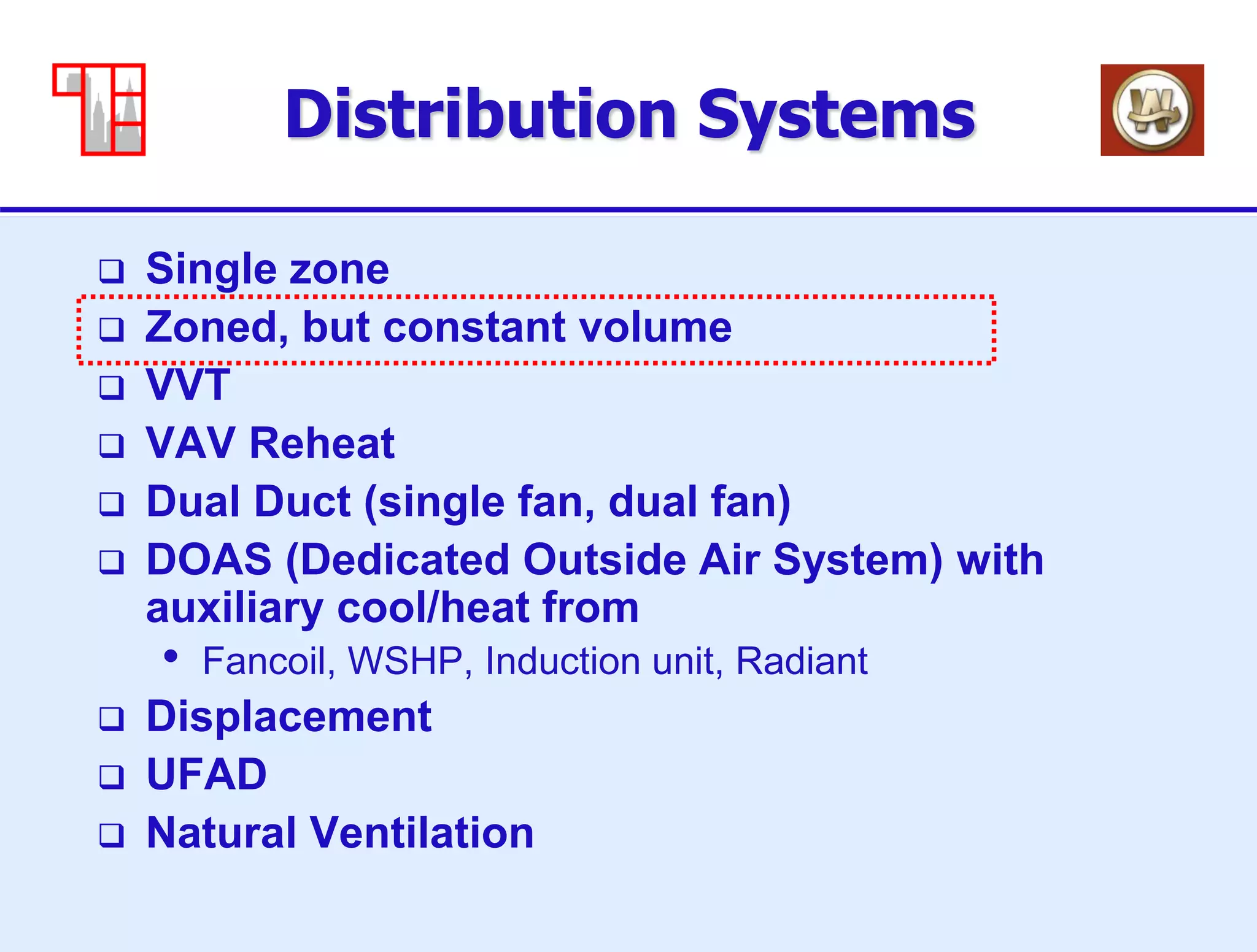
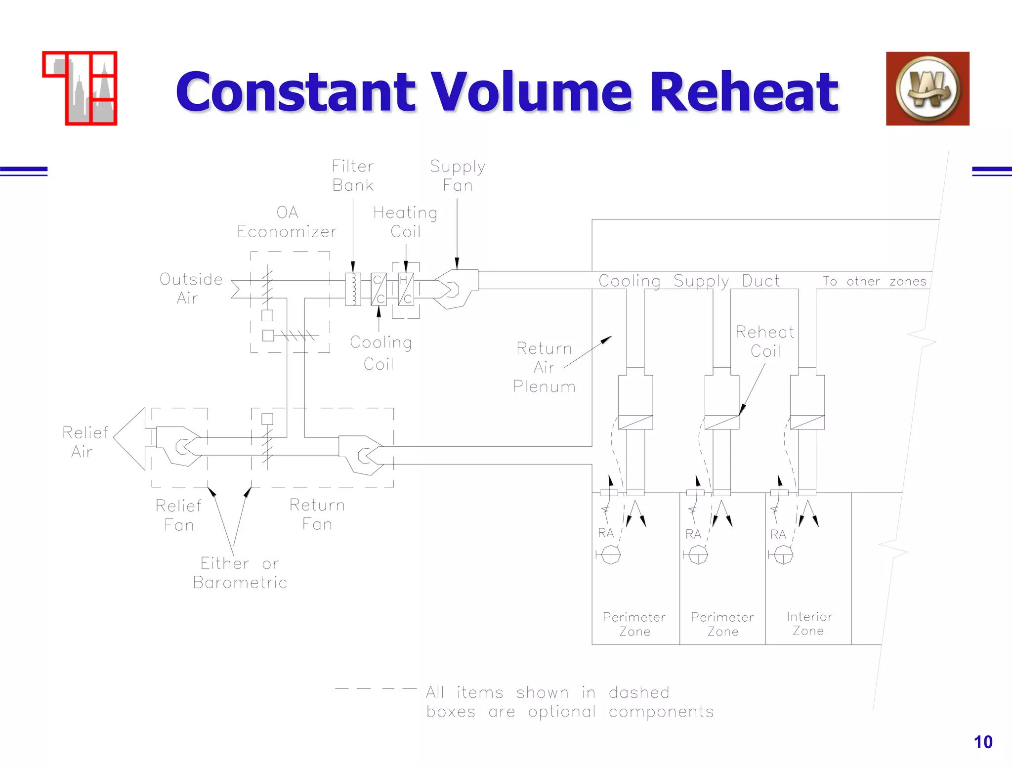
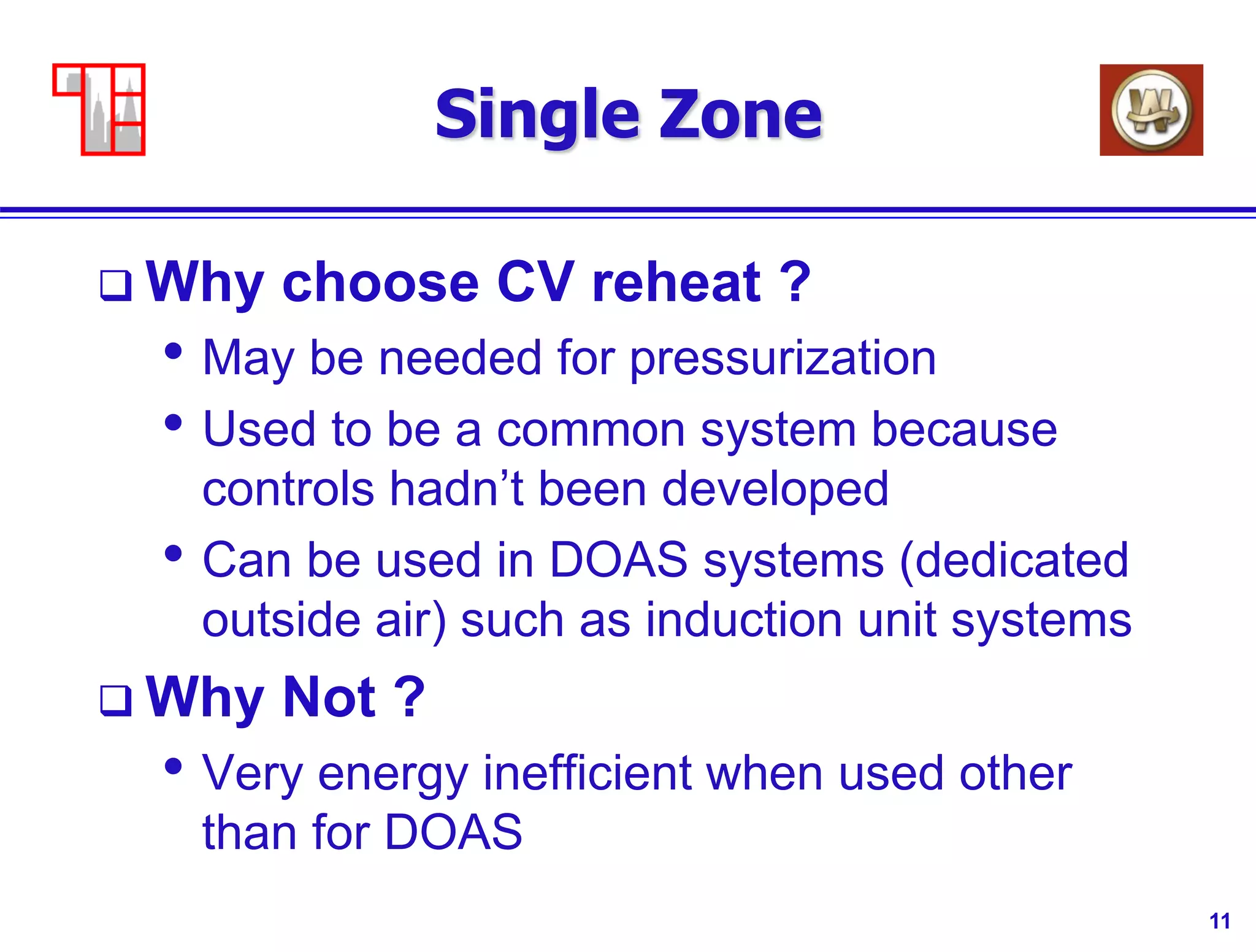
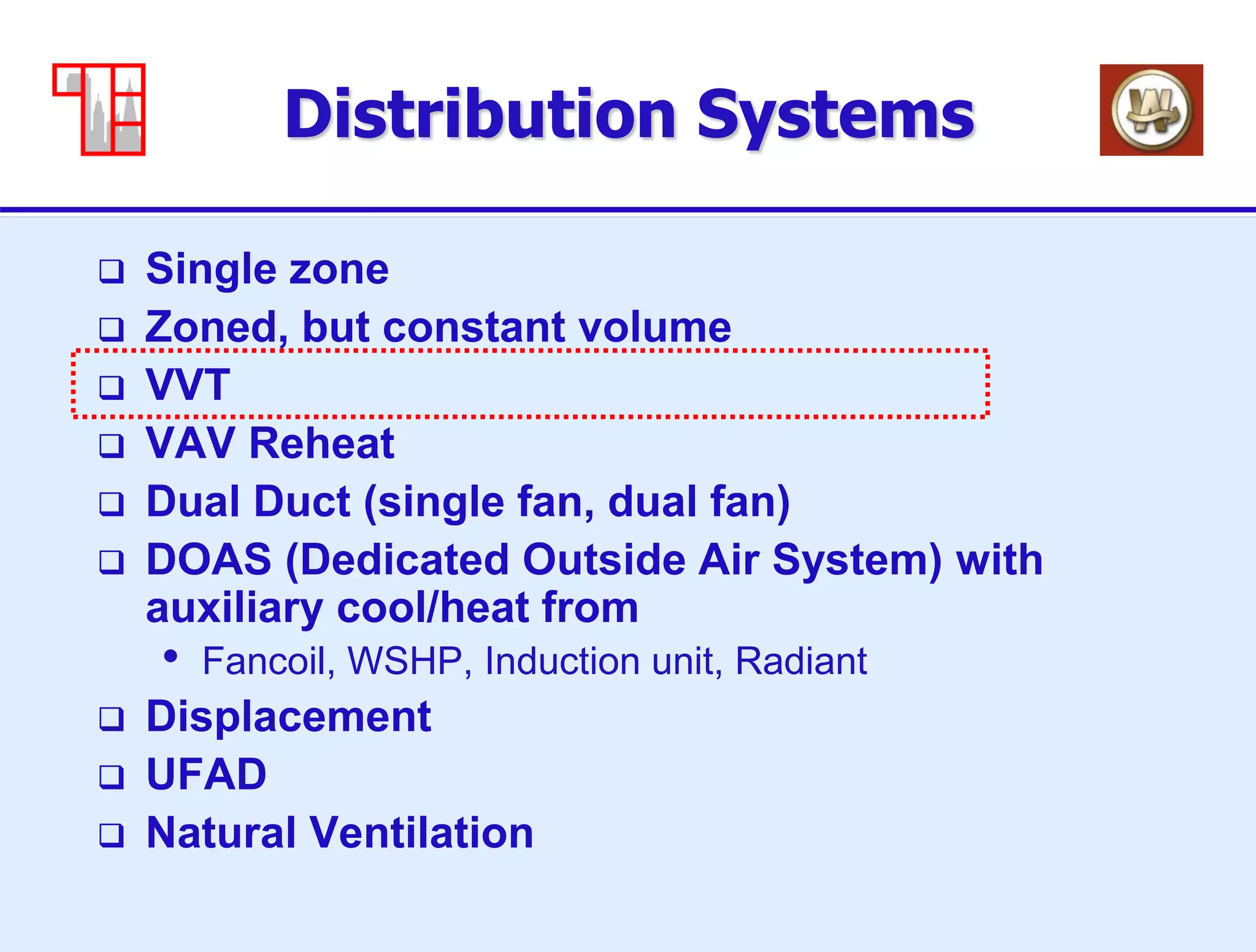
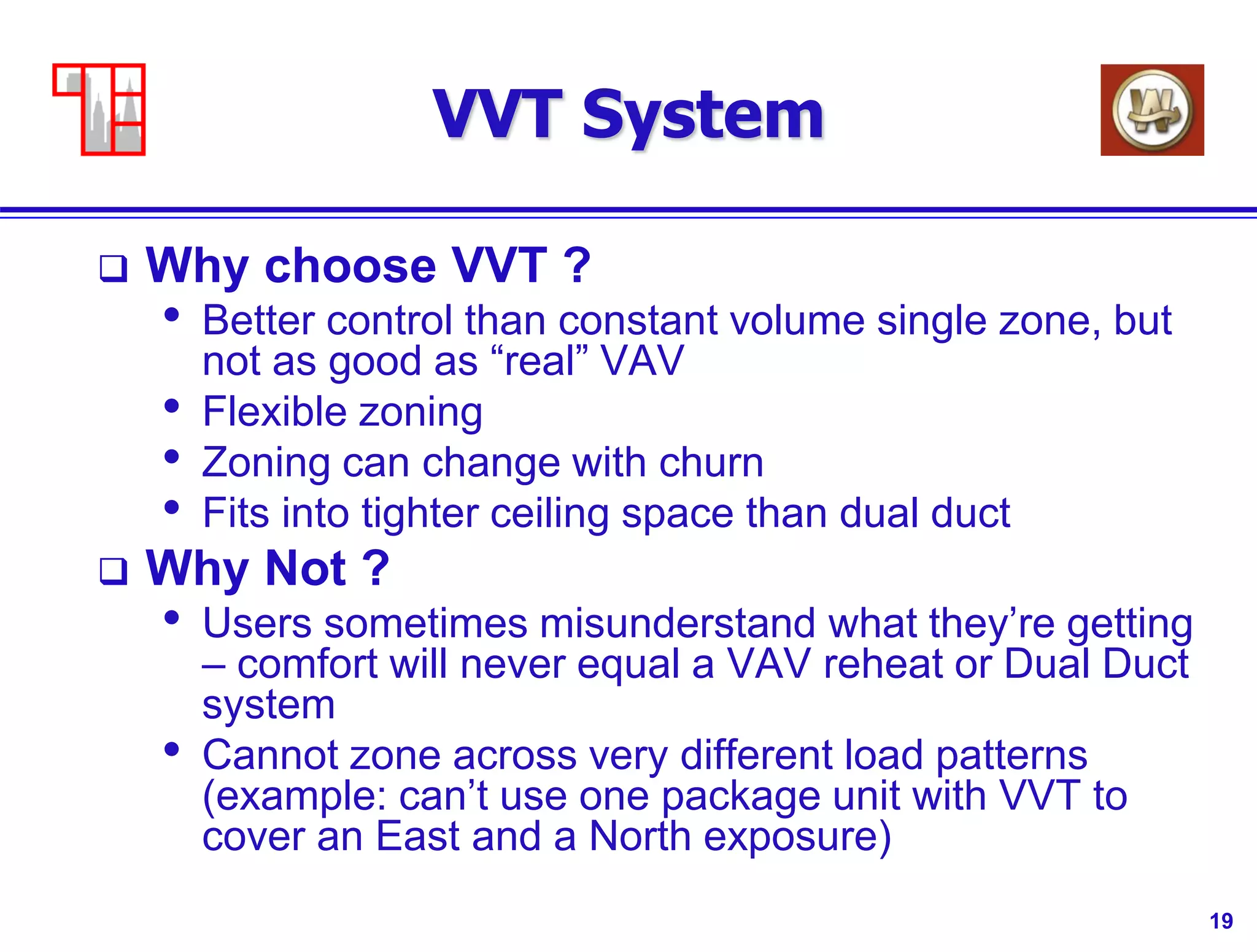
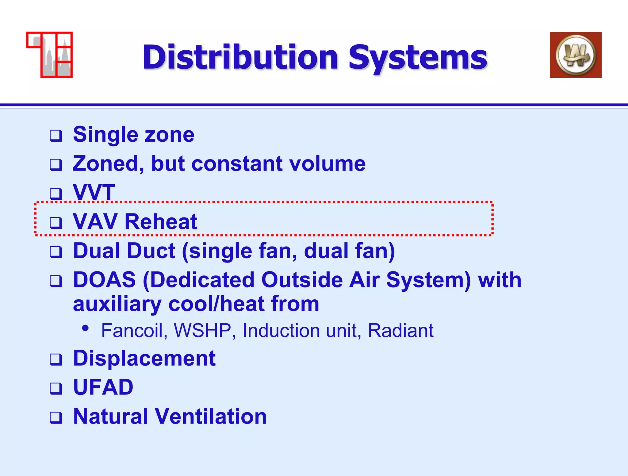
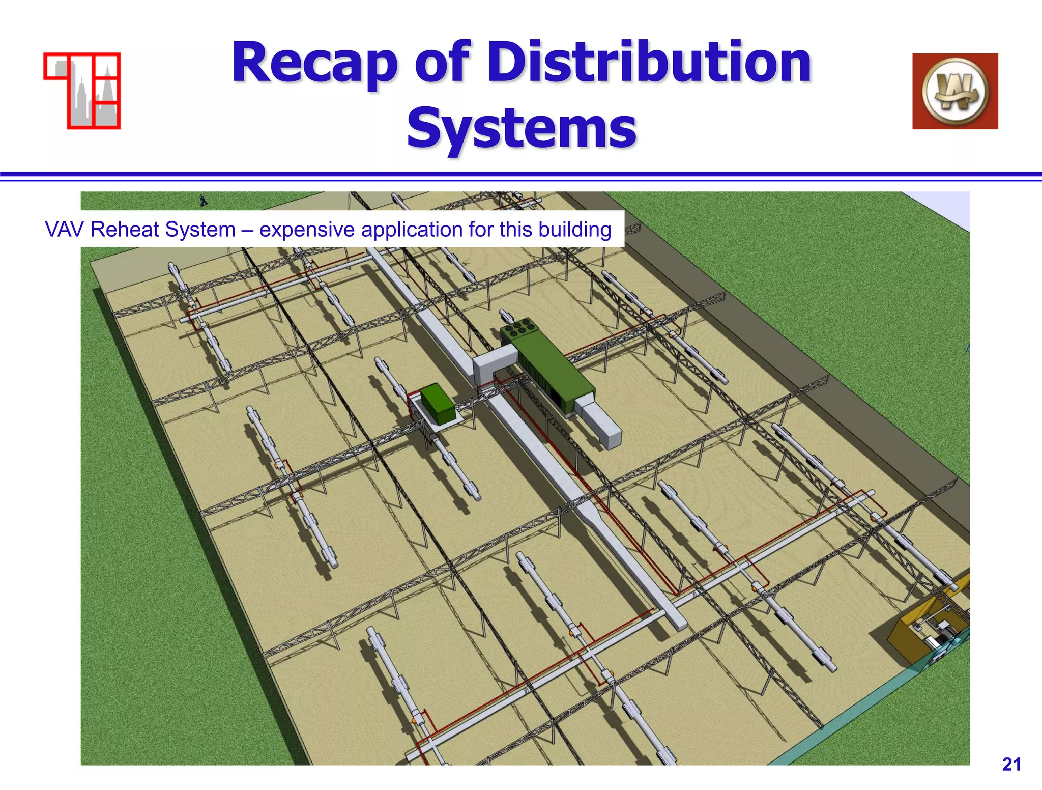
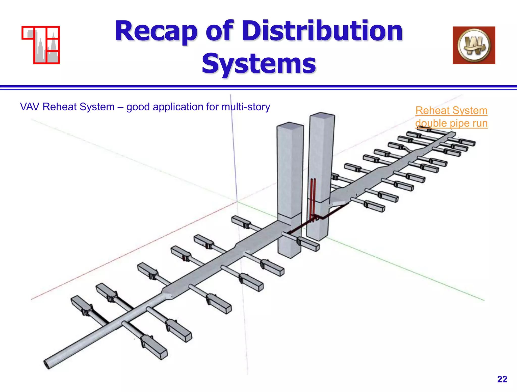
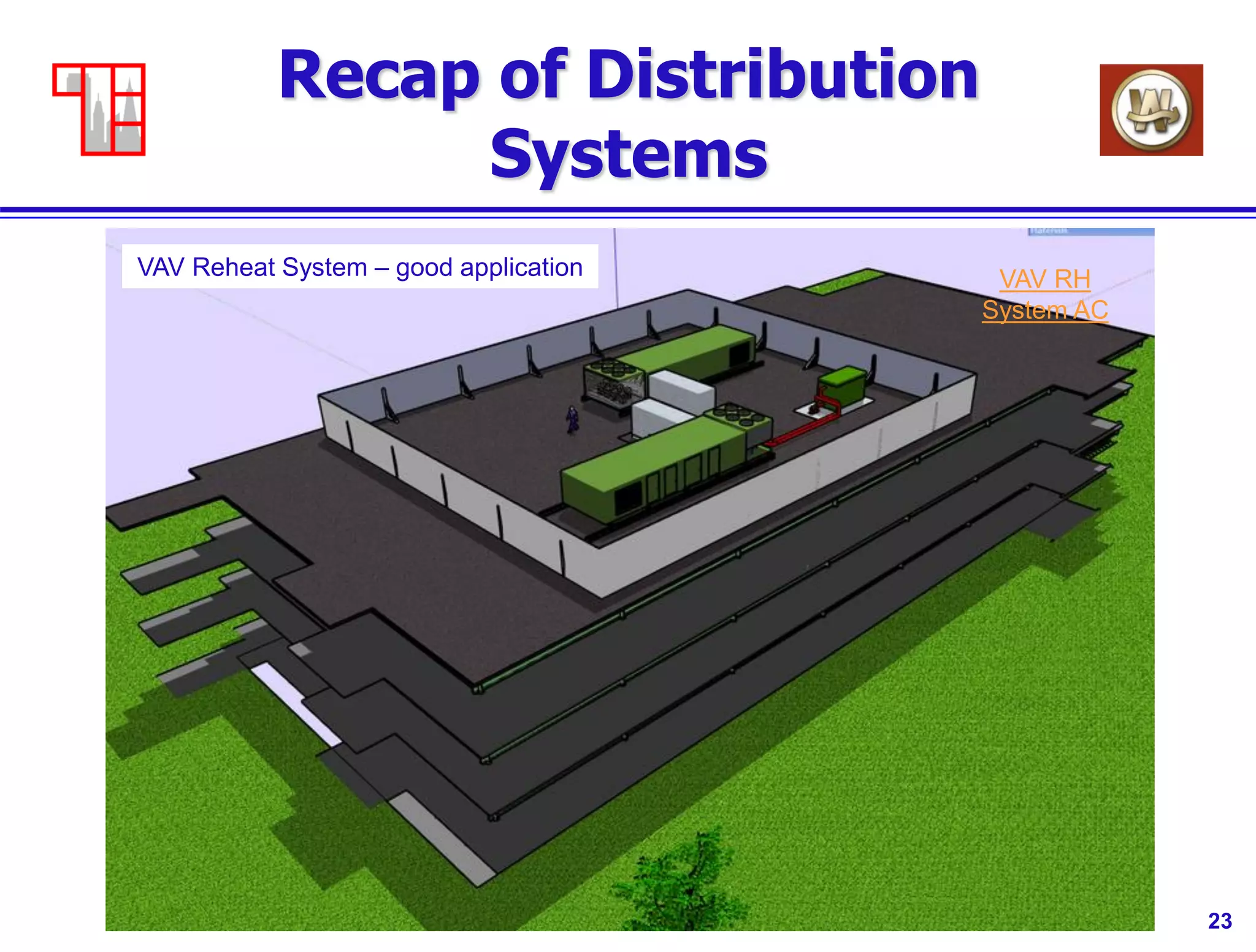
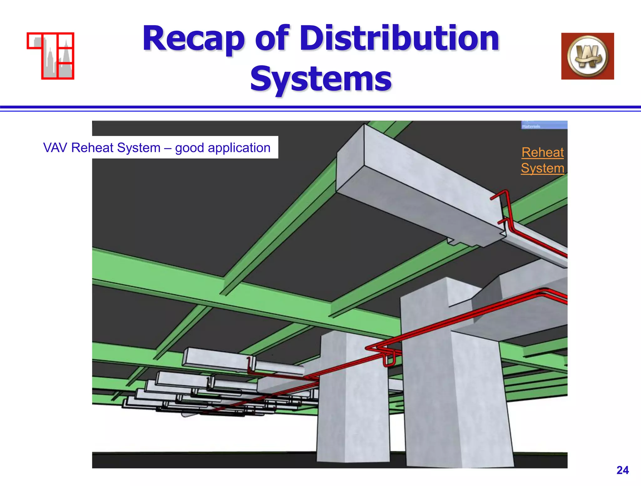
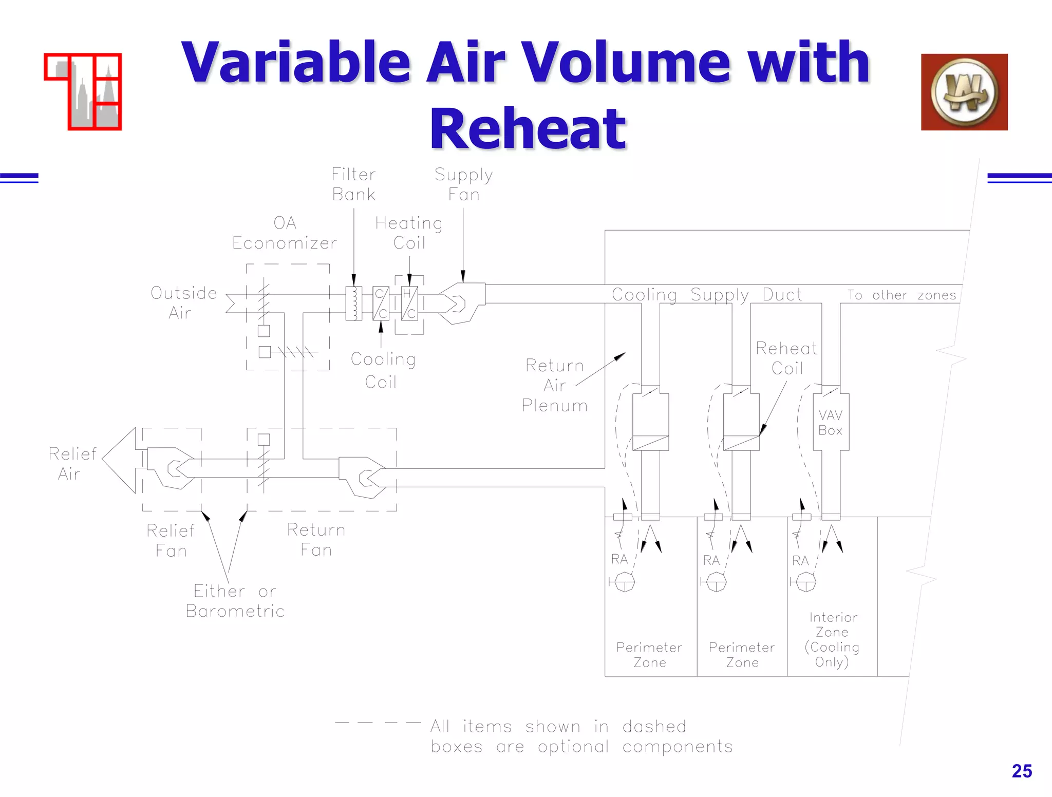
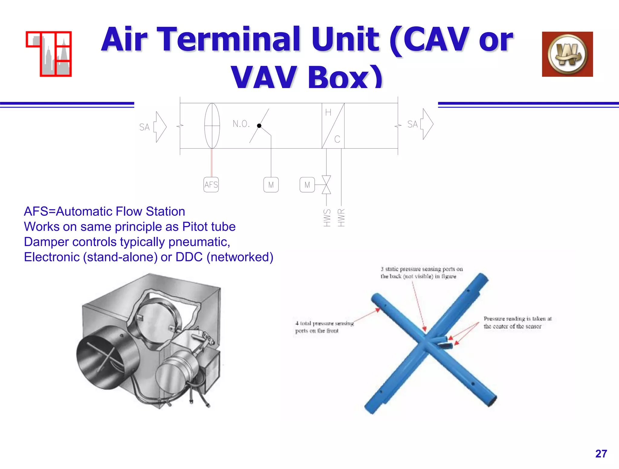
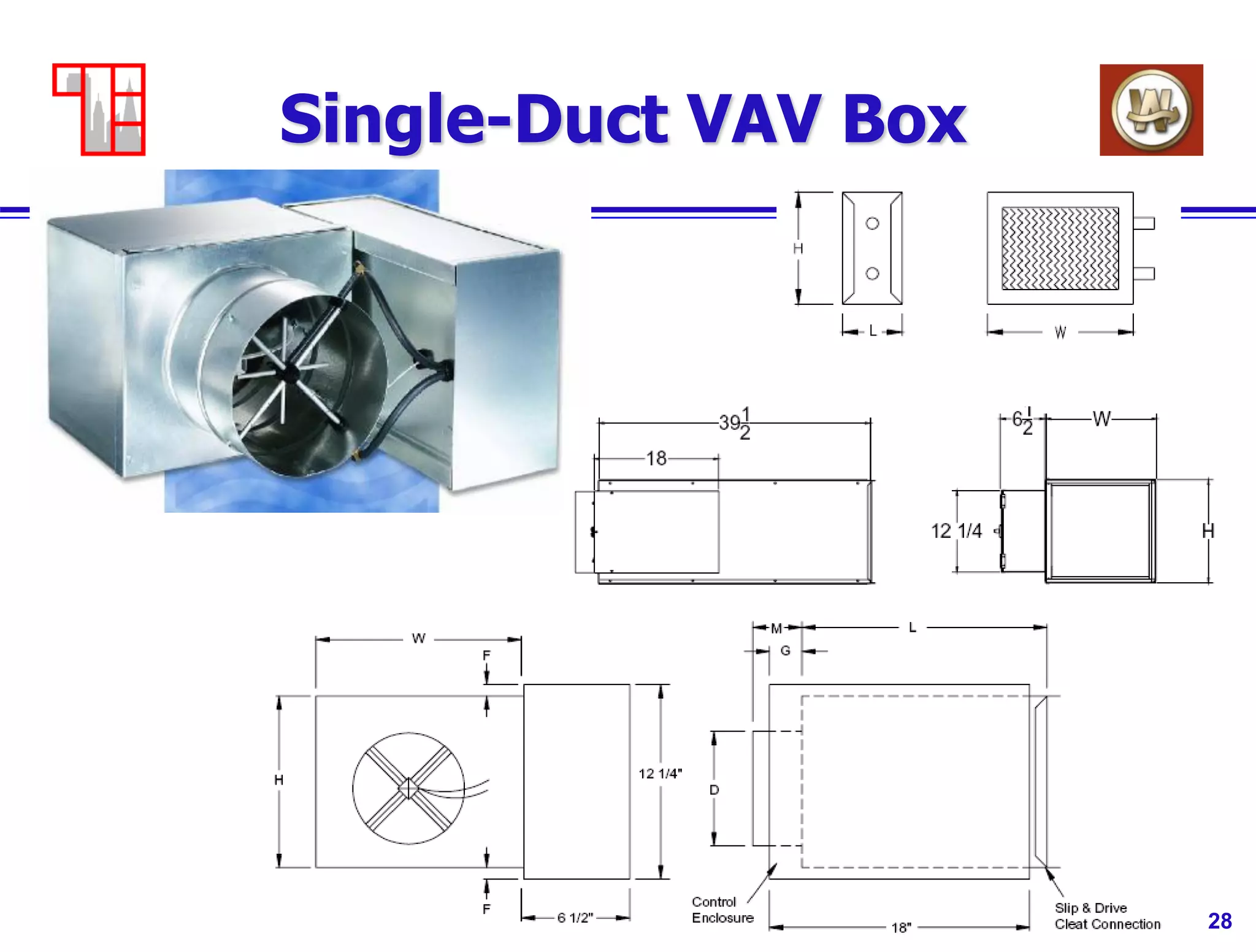
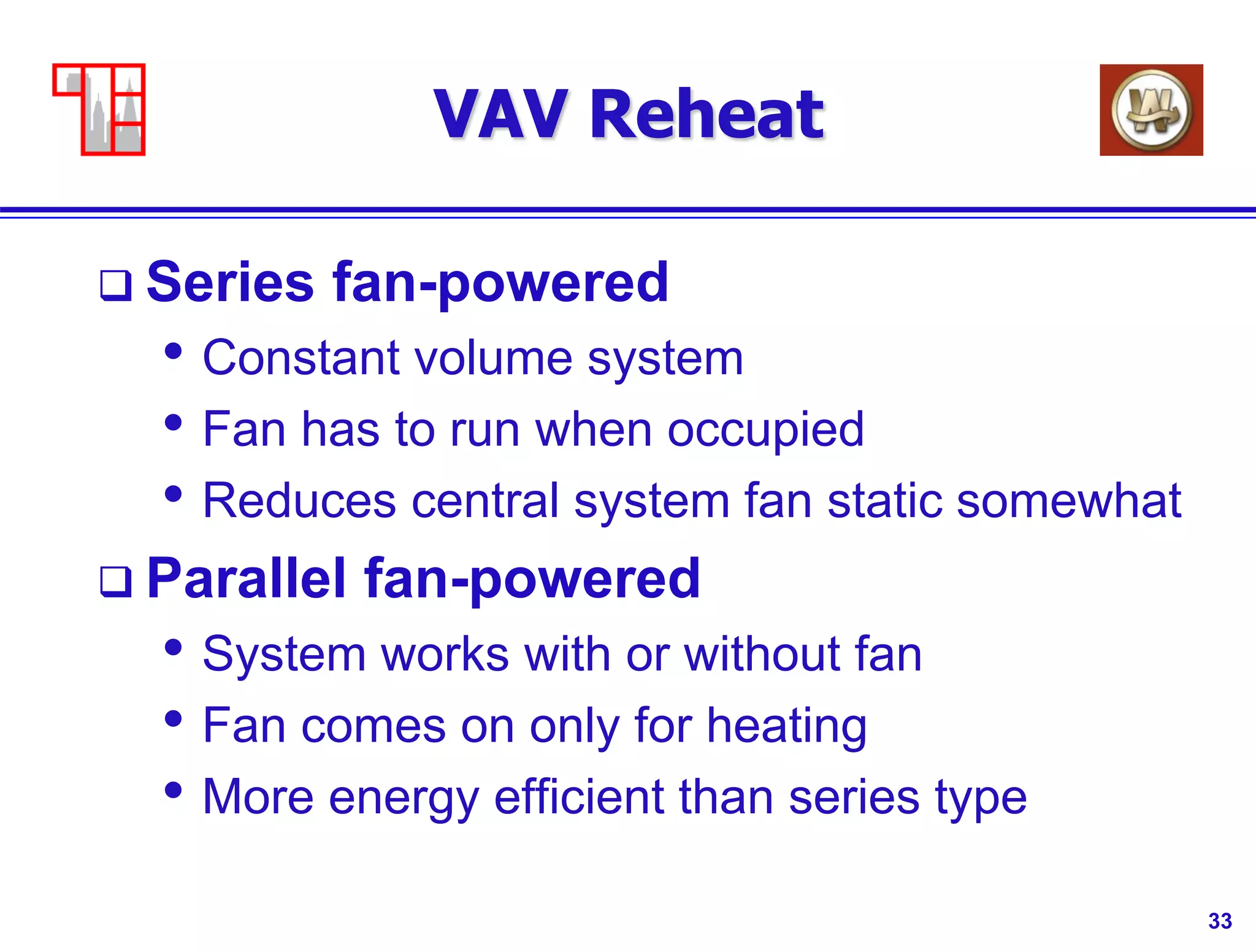
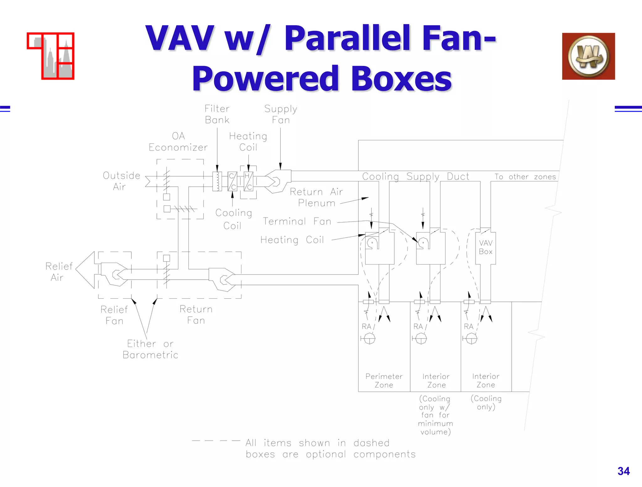
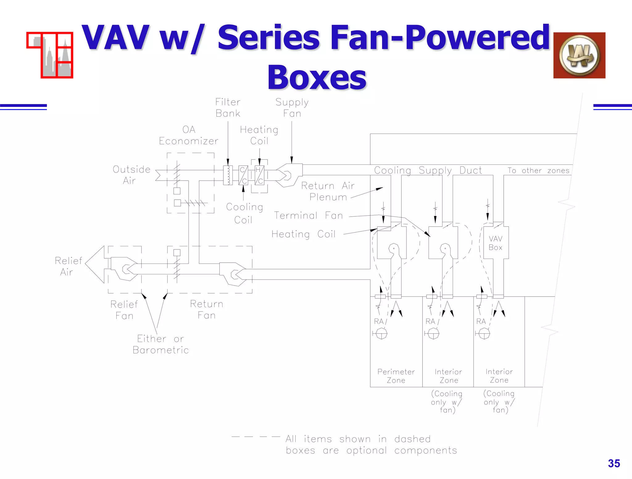
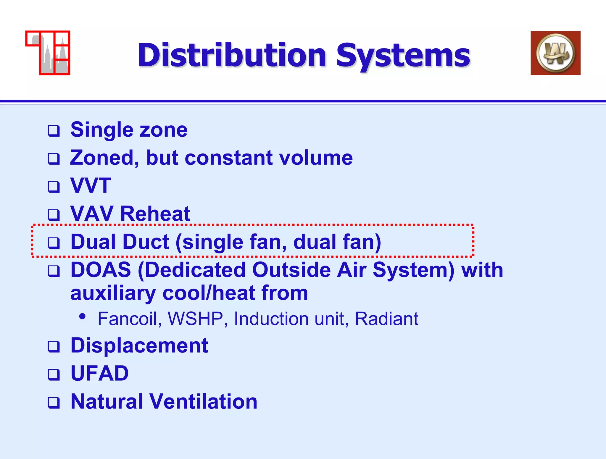
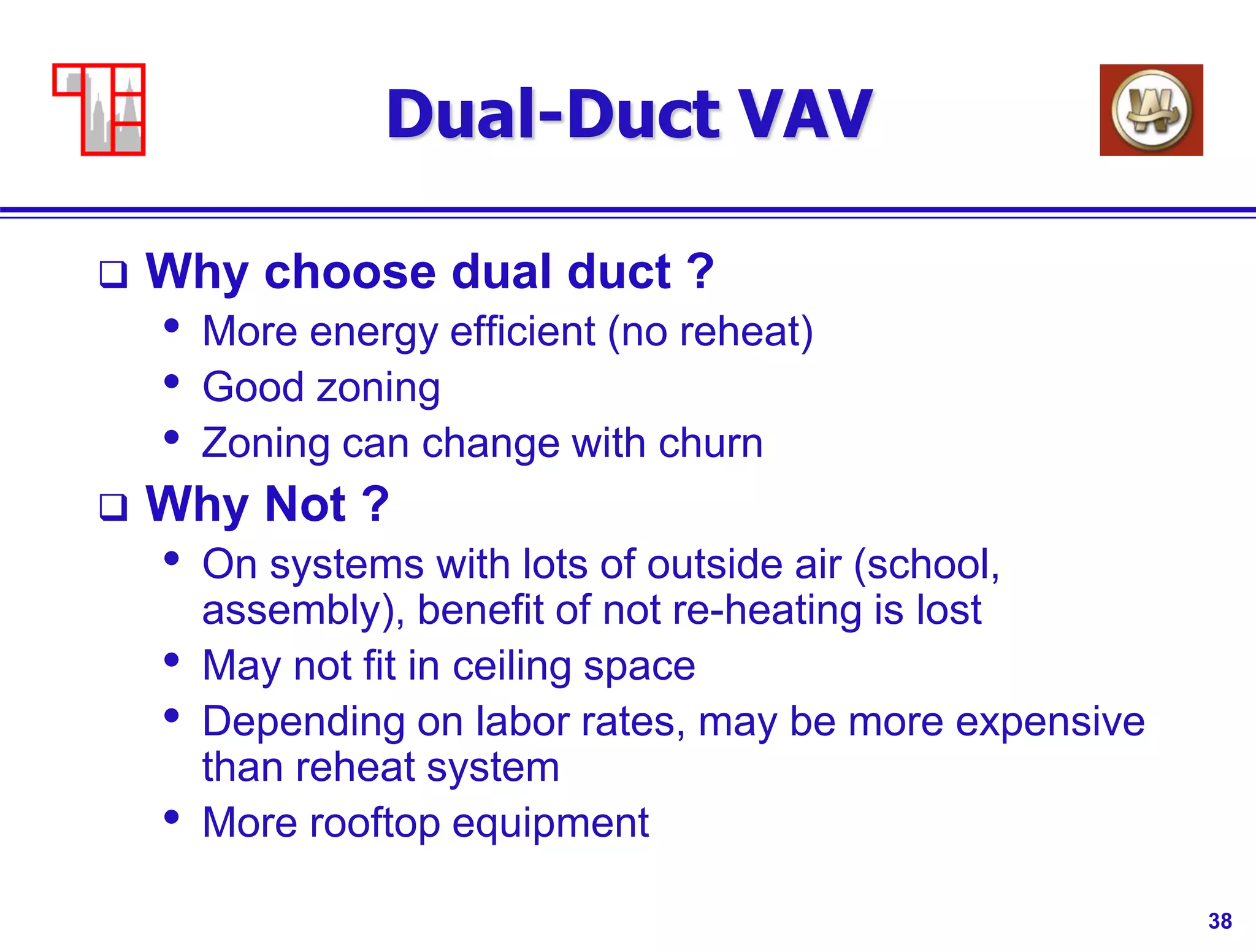
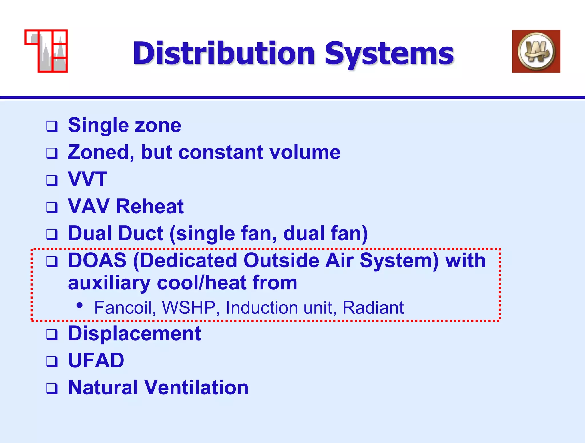
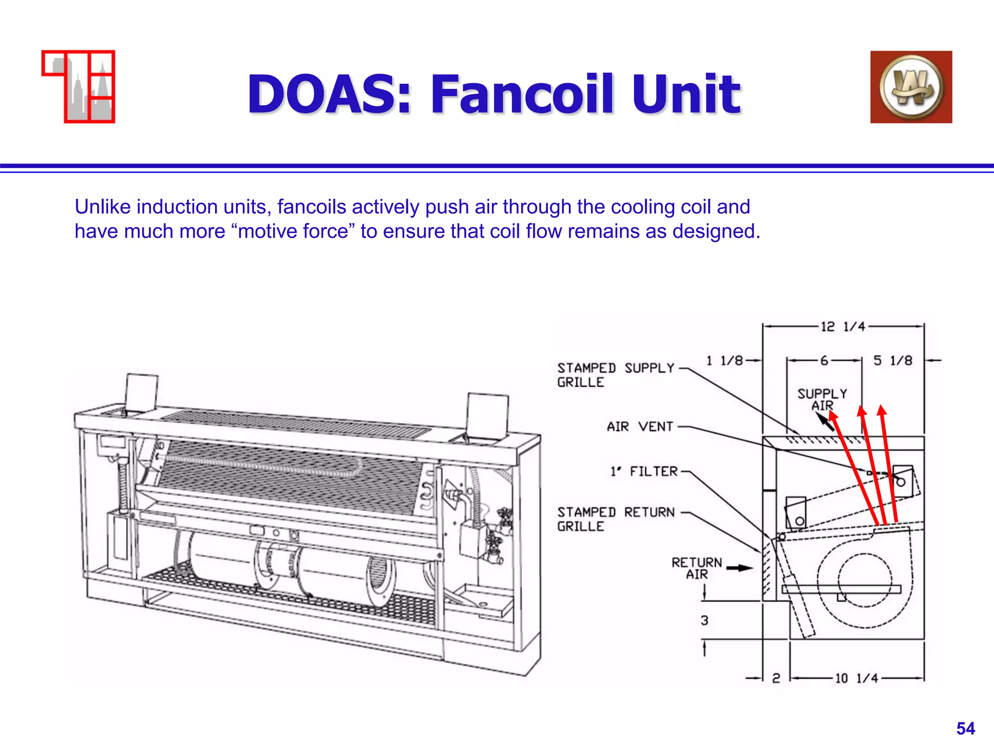
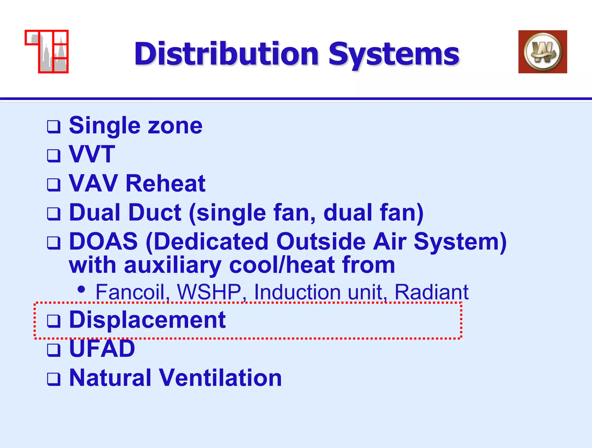
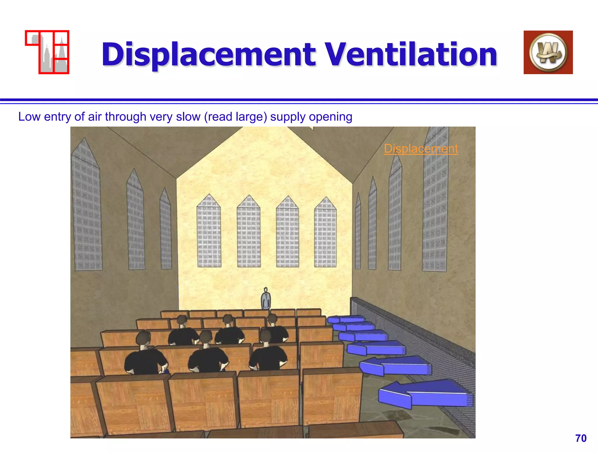
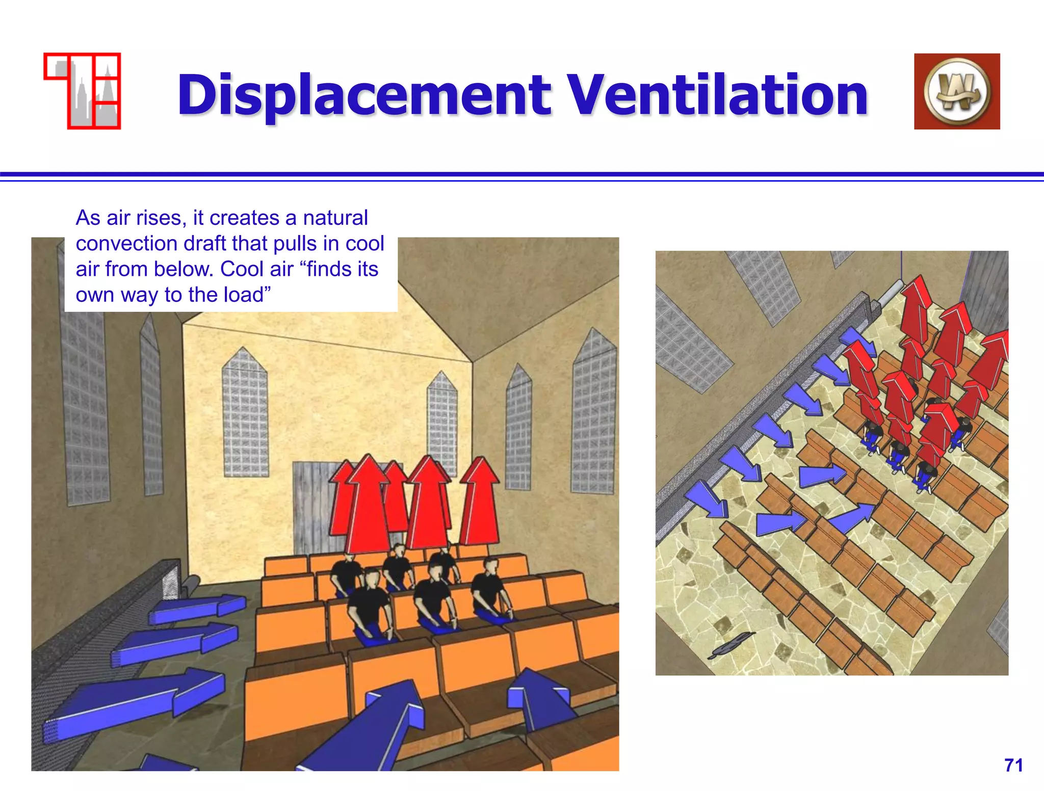
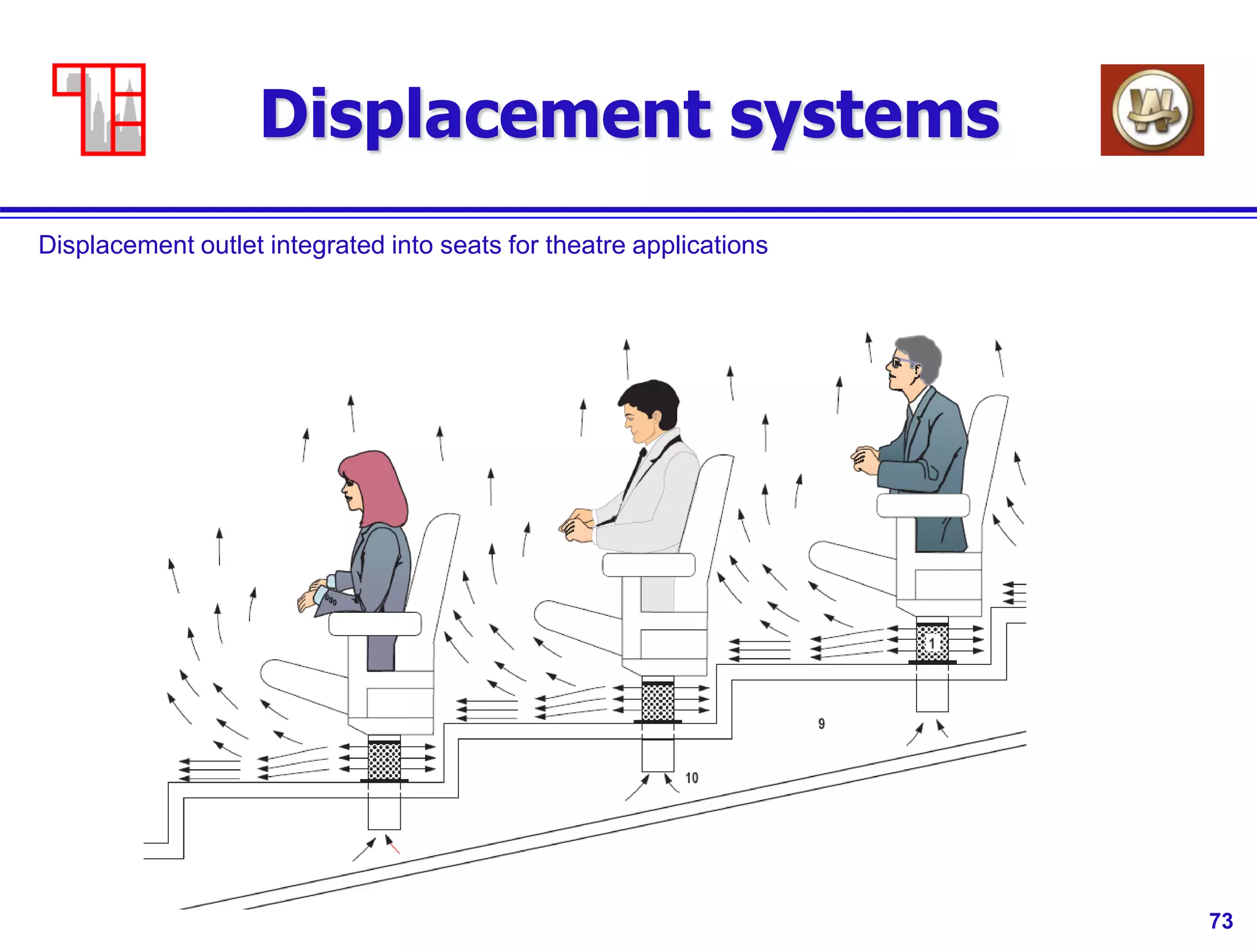
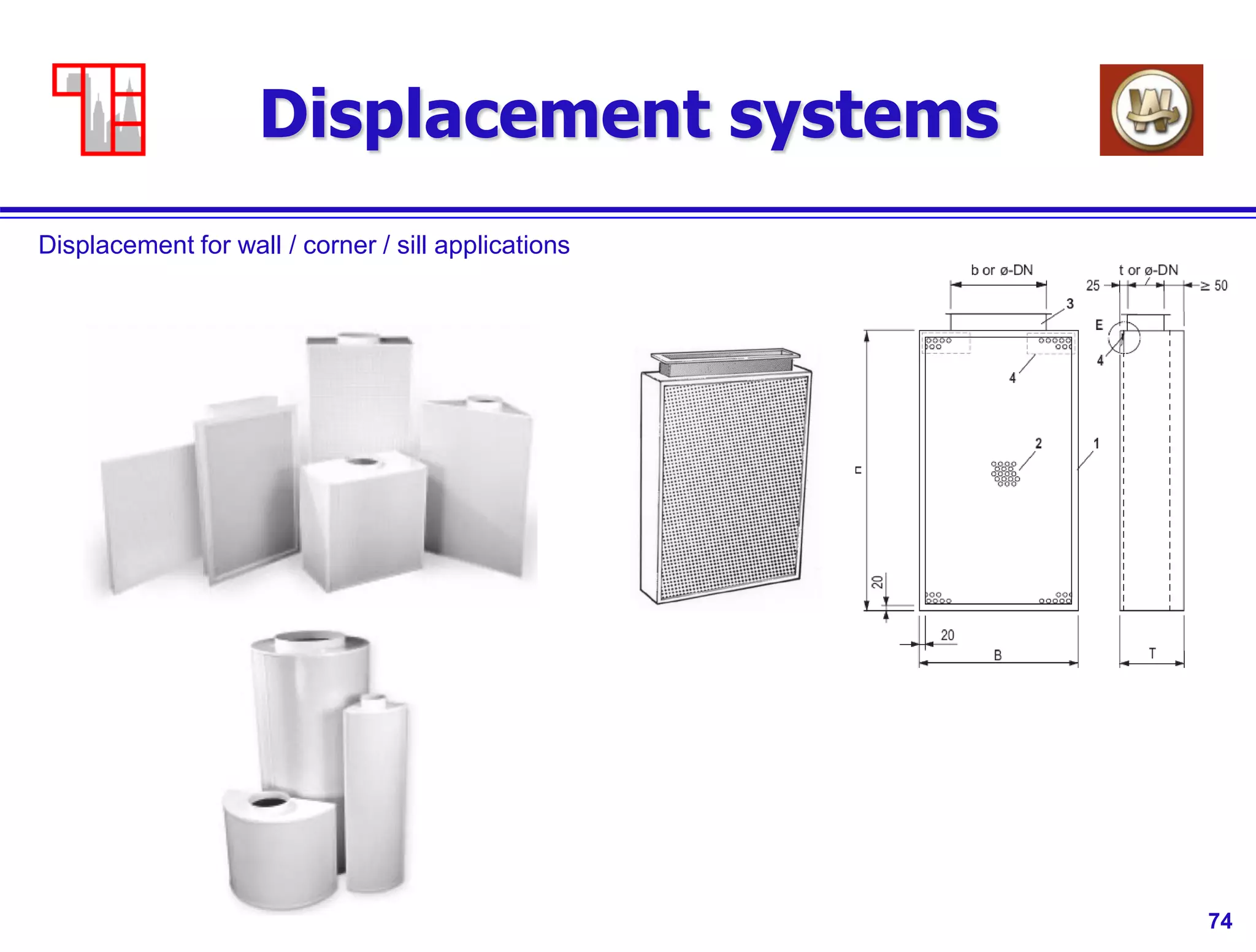
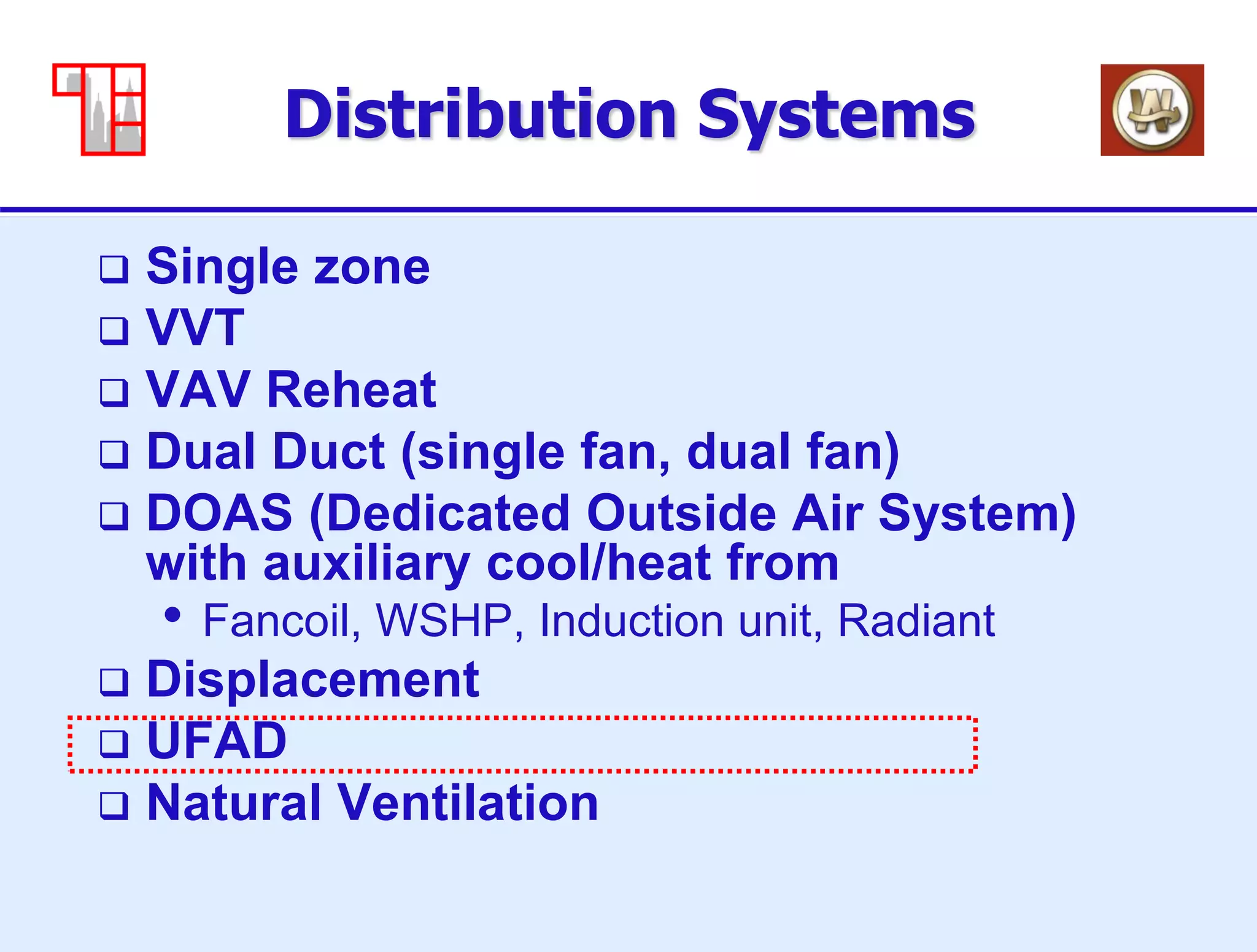
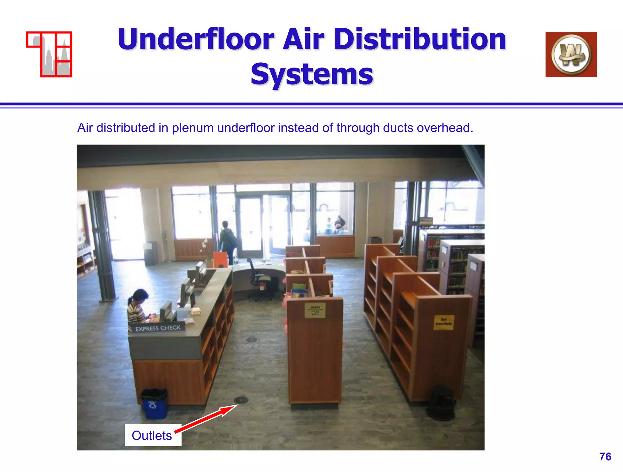
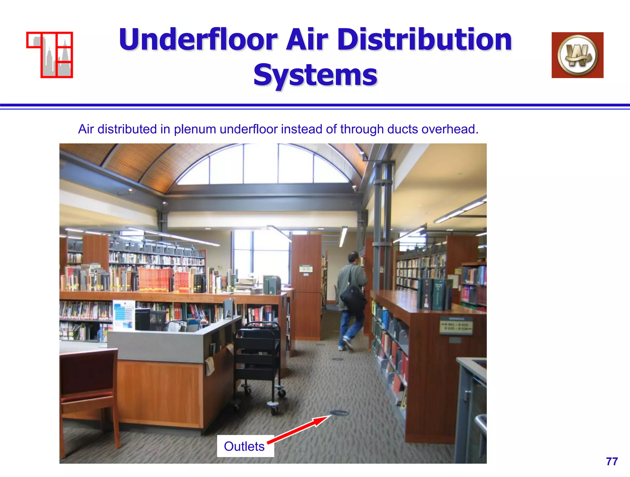
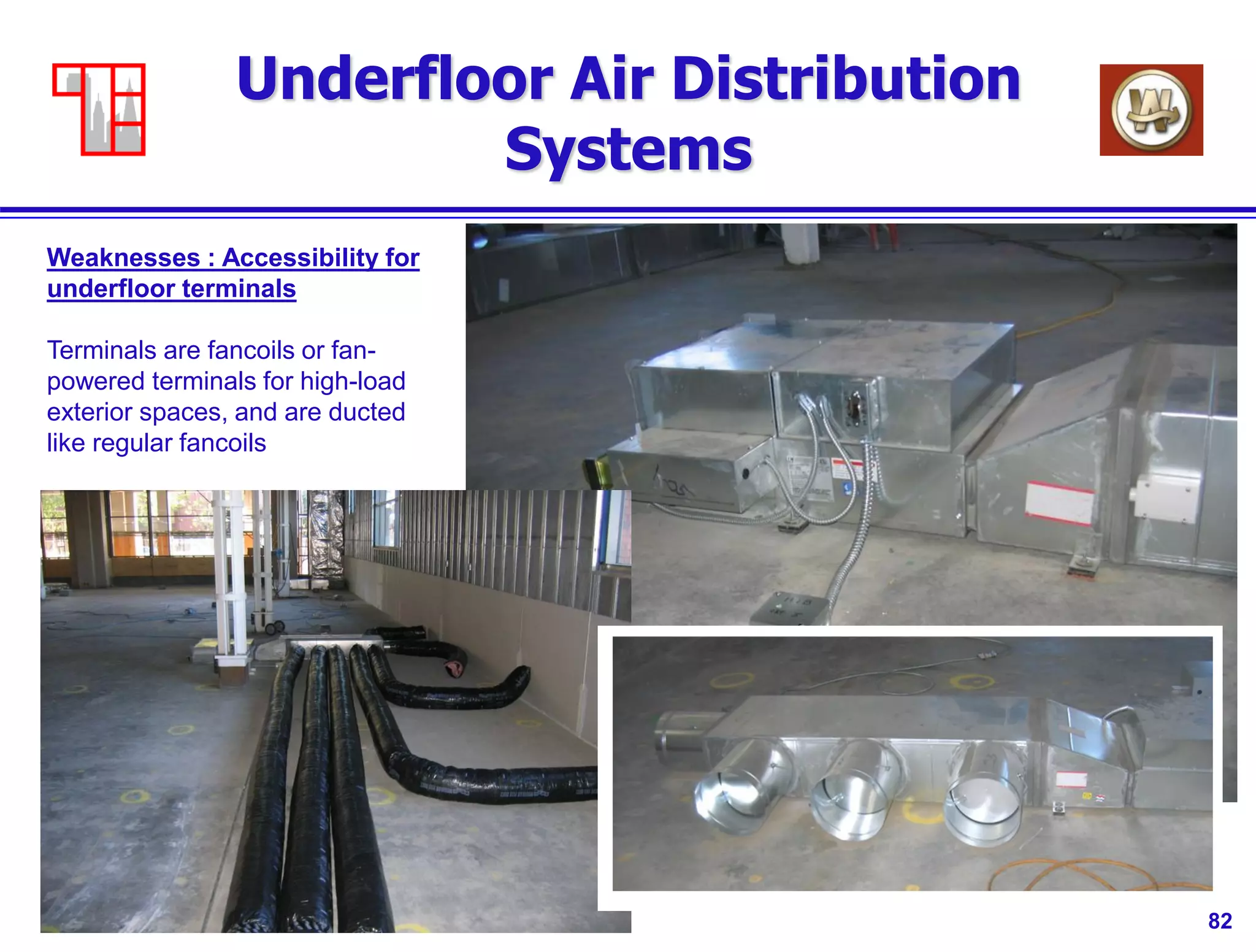
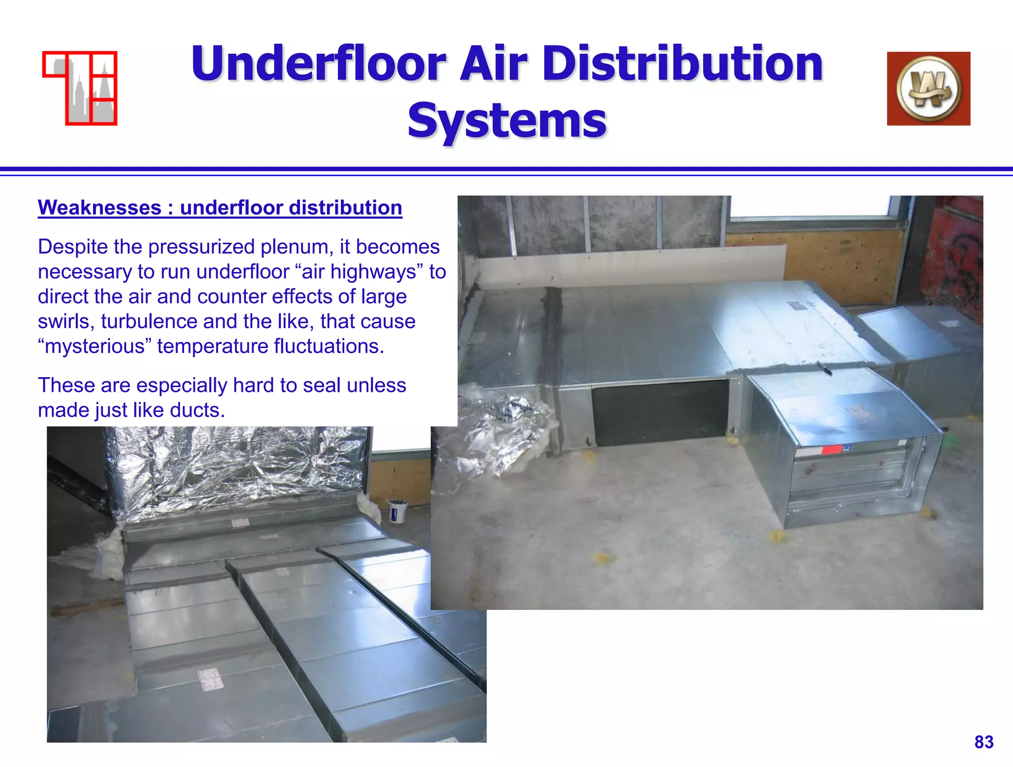
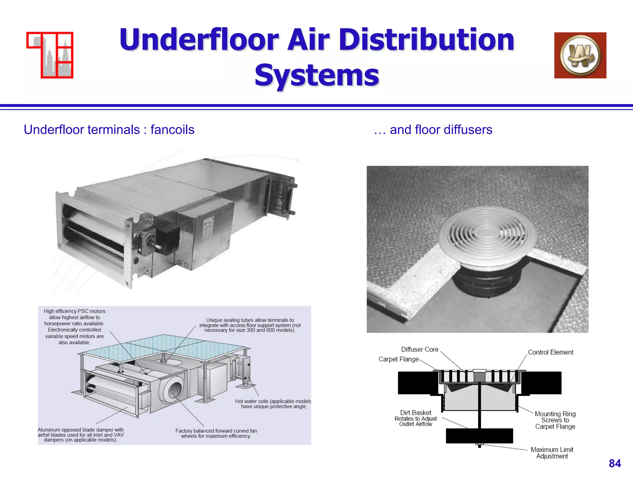
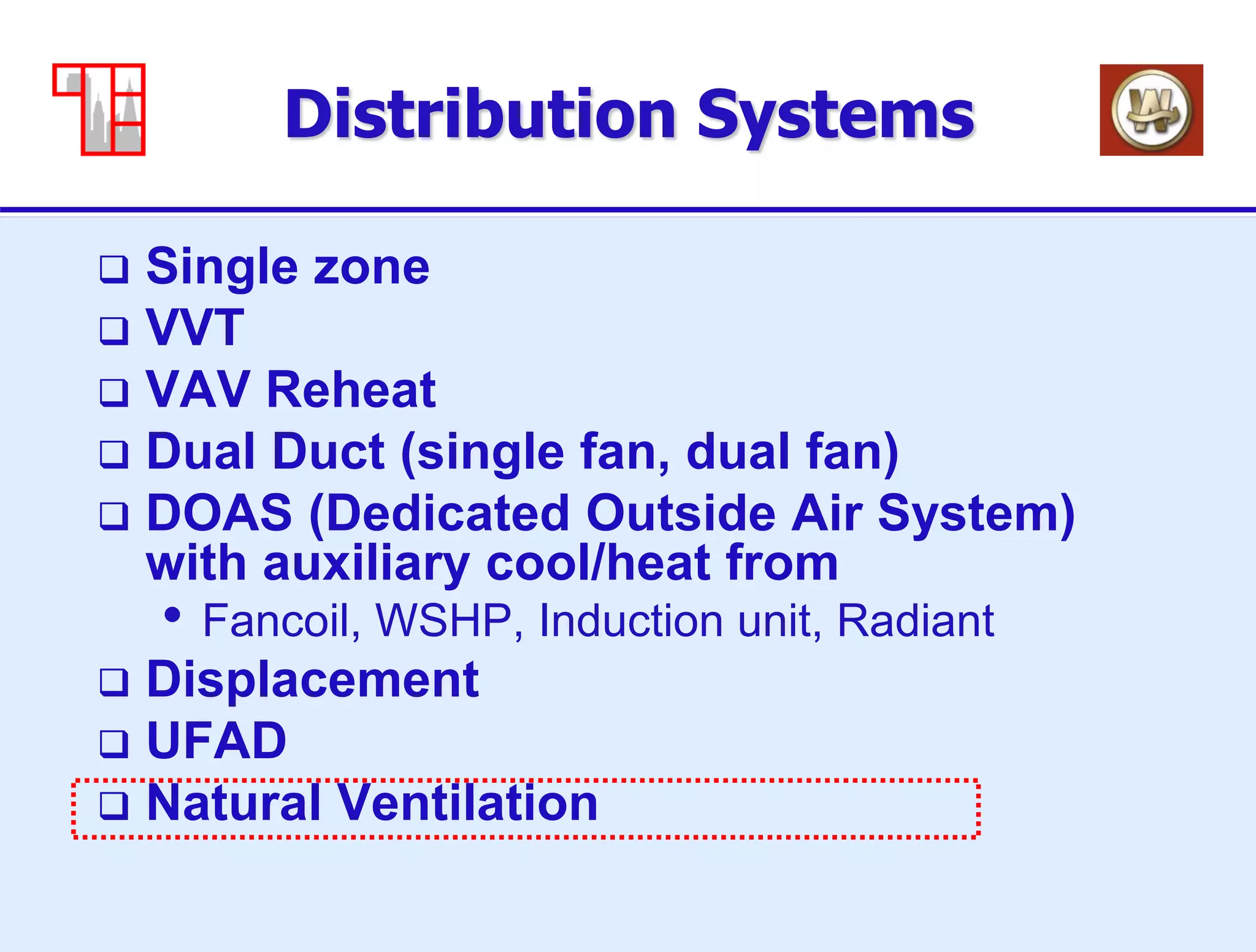
X472 HVAC System Design
Considerations
Class 3 – Distribution Systems
Todd Gottshall, PE
Western Allied
Redwood City, CA
Reinhard Seidl, PE
Taylor Engineering
Alameda, CA
Fall 2015
Mark Hydeman, PE
Continual
San Francisco, CA
2
General
 Contact Information
Reinhard: rseidl@taylor-engineering.com
Mark: mhydeman@continual.net
Todd: tgottshall@westernallied.com
 Text
• None
 Slides
• download from web before class
• Log in to Box at https://app.box.com/login
• Username: x472student@gmail.com
• Password: x472_student (case sensitive)
3
Course Outline
Date Class Topic Teacher
9/02/2015 1. Introduction / Systems Overview / walkthrough RS
9/09/2015 2. Generation Systems TG
9/16/2015 3. Distribution Systems RS
9/23/2015 4. Central Plants TG
9/30/2015 5. System Selection 1 - class exercises RS
10/07/2015 6. Specialty Building types (High rise, Lab, Hospital,
Data center)
TG
10/14/2015 7. System Selection 2 - class exercises RS
10/21/2015 8. Construction codes and Project delivery methods TG
10/28/2015 9. 2013 T24 and LEED v4 MH
11/04/2015 10. Life-Cycle Cost Analysis and exam hand-out TG
There are three instructors for this class. Todd Gottshall (TG), Reinhard Seidl (RS)
and Mark Hydeman (MH). The schedule below shows what topics will be covered by
who, and in what order.
4
Birds Eye View of Systems
 Single Story – tilt-up
• Single zone rooftop AC
• Split units, VRV
 Two-Story
• Single zone rooftop AC
• Multi-zone rooftop AC
 3-8 Story
• Centralized systems
• Dual Duct
• VAV RH
 High-rise
• Floor-by-floor
• Built-up Systems
• Condenser loops, tenant heat
pumps
 Campus Systems
• Central plant, airside/water
side economizers, thermal
energy storage
• Cogeneration
 Specialty Systems
• Hotel
• Library
• Laboratory
• Underfloor
• Natural Ventilation
• Direct/Indirect
• Cascading cooling towers
5
Overview
 Non-campus distribution systems
(air and water)
 Central plant types and distribution
systems
6
Distribution Systems
 Single zone
 Zoned, but constant volume
 VVT
 VAV Reheat
 Dual Duct (single fan, dual fan)
 DOAS (Dedicated Outside Air System) with
auxiliary cool/heat from
• Fancoil, WSHP, Induction unit, Radiant
 Displacement
 UFAD
 Natural Ventilation
7
Small packaged unit layout
VVT
System
8
Single Zone
 Why choose single zone ?
• Cheap
• Simple
• Provides fairly good temperature zones
 Why Not ?
• Doesn’t work well for multi-story buildings
because of multiple shafts
9
Distribution Systems
 Single zone
 Zoned, but constant volume
 VVT
 VAV Reheat
 Dual Duct (single fan, dual fan)
 DOAS (Dedicated Outside Air System) with
auxiliary cool/heat from
• Fancoil, WSHP, Induction unit, Radiant
 Displacement
 UFAD
 Natural Ventilation
10
Constant Volume Reheat
11
Single Zone
 Why choose CV reheat ?
• May be needed for pressurization
• Used to be a common system because
controls hadn’t been developed
• Can be used in DOAS systems (dedicated
outside air) such as induction unit systems
 Why Not ?
• Very energy inefficient when used other
than for DOAS
12
Distribution Systems
 Single zone
 Zoned, but constant volume
 VVT
 VAV Reheat
 Dual Duct (single fan, dual fan)
 DOAS (Dedicated Outside Air System) with
auxiliary cool/heat from
• Fancoil, WSHP, Induction unit, Radiant
 Displacement
 UFAD
 Natural Ventilation
13
VVT System Requires a Bypass
 If we vary airflow on a constant volume unit we have too
little airflow on a constant volume system = frozen unit
Frozen
compressor,
suction line
Frozen
evaporator
14
VVT System
 Until very recently, could not get
systems with low tonnage (< 10 tons
or so) with variable speed drive
 Had to use bypass damper instead
 Note: recently, thanks to “digital
scroll”, small tonnage VAV units have
started to appear.
15
VVT System
 New 2013 T24 requires small tonnage
units to be multi-stage
 See http://www.energy.ca.gov/title24/2013standards/index.html
 Prescriptive requirements section
140.4.m (fan speed control) and
section 140.4.e.5 (compressor stages)
as part of economizer requirements
16
VVT System
17
VVT System
18
VVT System
19
VVT System
 Why choose VVT ?
• Better control than constant volume single zone, but
not as good as “real” VAV
• Flexible zoning
• Zoning can change with churn
• Fits into tighter ceiling space than dual duct
 Why Not ?
• Users sometimes misunderstand what they’re getting
– comfort will never equal a VAV reheat or Dual Duct
system
• Cannot zone across very different load patterns
(example: can’t use one package unit with VVT to
cover an East and a North exposure)
20
Distribution Systems
 Single zone
 Zoned, but constant volume
 VVT
 VAV Reheat
 Dual Duct (single fan, dual fan)
 DOAS (Dedicated Outside Air System) with
auxiliary cool/heat from
• Fancoil, WSHP, Induction unit, Radiant
 Displacement
 UFAD
 Natural Ventilation
21
Recap of Distribution
Systems
VAV Reheat System – expensive application for this building
22
Recap of Distribution
Systems
VAV Reheat System – good application for multi-story Reheat System
double pipe run
23
Recap of Distribution
Systems
VAV Reheat System – good application VAV RH
System AC
24
Recap of Distribution
Systems
VAV Reheat System – good application Reheat
System
25
Variable Air Volume with
Reheat
26
VAV Reheat
 Why choose VAV Reheat ?
• Good control for multiple floors
• Flexible
• Zoning can change with churn
• Fits into tighter ceiling space than dual duct
 Why Not ?
• More expensive than single zone
• Re-heats
• Typically less energy efficient than dual duct
27
Air Terminal Unit (CAV or
VAV Box)
AFS=Automatic Flow Station
Works on same principle as Pitot tube
Damper controls typically pneumatic,
Electronic (stand-alone) or DDC (networked)
28
Single-Duct VAV Box
29
VAV Reheat
 Problem with reheat ?
• Just that. Reheat means destroying energy:
• First cool the air
• Then heat it back up
• You pay 2x
• Code (CA Title 24) limits the amount of reheat you can
do (see section on dual max control T24, 140.4.d)
 What alternatives ?
• Use fan-powered terminals
• Provide heating by heating space air, not primary
supply air (in some ways, this is what a good dual duct
design does)
30
VAV Box Minimums (from
Title-24)
 Reheat, T24 allows maximum of (with
DDC control):
• 20% of design cooling airflow
• ventilation requirements (see below)
 Ventilation Minimum Requirement =
Maximum of:
• 0.15 CFM/square foot
• 15 CFM/person
31
Fan-powered box
ensures constant
volume
Series Fan-Powered VAV
Box
32
Parallel Fan-Powered VAV
Box
33
VAV Reheat
 Series fan-powered
• Constant volume system
• Fan has to run when occupied
• Reduces central system fan static somewhat
 Parallel fan-powered
• System works with or without fan
• Fan comes on only for heating
• More energy efficient than series type
34
VAV w/ Parallel Fan-
Powered Boxes
35
VAV w/ Series Fan-Powered
Boxes
36
Distribution Systems
 Single zone
 Zoned, but constant volume
 VVT
 VAV Reheat
 Dual Duct (single fan, dual fan)
 DOAS (Dedicated Outside Air System) with
auxiliary cool/heat from
• Fancoil, WSHP, Induction unit, Radiant
 Displacement
 UFAD
 Natural Ventilation
37
Dual-Duct VAV
Dual Duct Dual Fan System Dual
Duct
System
38
Dual-Duct VAV
 Why choose dual duct ?
• More energy efficient (no reheat)
• Good zoning
• Zoning can change with churn
 Why Not ?
• On systems with lots of outside air (school,
assembly), benefit of not re-heating is lost
• May not fit in ceiling space
• Depending on labor rates, may be more expensive
than reheat system
• More rooftop equipment
39
Single-Fan Dual-Duct VAV
40
Dual-Fan Dual-Duct VAV
41
Dual-Duct VAV Box
42
Dual-Duct VAV Box
DD terminals often feature a mixing
plenum at the outlet to prevent cold
air going one way, and hot air going
the other way
DD is harder to
route through a
building than a
VAV reheat
system!
43
Distribution Systems
 Single zone
 Zoned, but constant volume
 VVT
 VAV Reheat
 Dual Duct (single fan, dual fan)
 DOAS (Dedicated Outside Air System) with
auxiliary cool/heat from
• Fancoil, WSHP, Induction unit, Radiant
 Displacement
 UFAD
 Natural Ventilation
44
DOAS Systems
Induction / Fancoil Unit System
High rise
Induction
45
Induction Units and Fancoil
Units
Note: when laying out
piping, consider the
H/W ratio of the building
to figure out whether it
is more cost effective to
run multiple risers with
short branches, or
fewer risers with longer
branches.
It’s easy to figure out,
just make a
spreadsheet with linear
feet of piping.
This is equally true for
VAV reheat piping
loops, and condenser
water loops for
WSHP’s.
One building facade Piping option 1 Piping option 2 ….. Piping option x
46
DOAS: Floor-by-floor units
One mech. Room per floor, one large heat pump
Boiler for
VAV
Reheat
Elevator
machine
room unit
Cooling
Towers
Makeup Air
Handler
47
DOAS
 Why choose DOAS system ?
• Small ductwork, small OA air handlers
• Easy calculation/control of ventilation
requirements
• Flexible
 Why Not ?
• Fairly expensive (many terminal units or
radiant panels)
• No airside economizer (big hit for Bay Area,
small hit for Florida)
48
DOAS: Induction Units
 Why choose Induction units/chilled beams ?
• No fan (no electrical at all in pneumatic control option)
• Small zones, individual control
• Low noise
 Why Not ?
• Very expensive (see article from May 2013)
• High static on DOAS fans (although much better in modern
chilled beam design) and constant volume, leading to high
annual fan power
• Noise (also better on modern designs)
• Older vertical units: high maintenance/hard to clean, loss of
capacity when carpet particles in coil reduce or eliminate
induction
49
DOAS: Induction Systems
Actually a re-cooling system, not
re-heating system: in winter,
outside air handler provides hot air
(hot enough for all zones). The
overheated zones are re-cooled
by the induction units.
50
DOAS: Induction Units
Nozzles at
base of unit
51
DOAS: Induction Systems
Induction units are often a maintenance problem, because when dirt accumulates in the coil,
there is very little static pressure from the induction effect. Unless coils stay clean, induced air
volume is reduced over time, until the units don’t cool effectively.
52
DOAS: Induction Systems
Chilled beams : passive and active (essentially, induction units)
53
DOAS: Induction Systems
Chilled beams : passive and active (essentially, induction units)
54
DOAS: Fancoil Unit
Unlike induction units, fancoils actively push air through the cooling coil and
have much more “motive force” to ensure that coil flow remains as designed.
55
DOAS: Fancoil units
 Why choose Fancoil units ?
• Flexible
• Small zones, individual control
• High local capacity
 Why Not ?
• Fairly expensive
• No airside economizer
• Possible leaks (for IDF/Data rooms)
56
DOAS: Fancoil Unit
High Internal loads,
quiet operation:
Chilled-water fancoil
Note spring isolation
hangers
57
DOAS: WSHP
 Why choose water-source heat pumps ?
• Flexible
• Small zones, individual control
• High local capacity
• Cool/heat on one circuit (uninsulated condenser water)
• Lower first cost than fancoil system
• Recover heat during simultaneous heating and cooling
 Why Not ?
• More expensive units (each has its own compressor)
• More maintenance intensive than fancoils
• Noisier than fancoils
• No airside economizer
58
DOAS: WSHP
Like fancoils, WSHP units can handle localized loads. They use condenser water (for heating and
cooling) instead of chilled water and hot water.
59
DOAS: WSHP
Unlike fancoils, WSHP units are harder to maintain, since they have many more parts – in particular,
they contain a compressor (often 207V or 480V) and a condenser, plus a control panel.
A fancoil contains just a fan (usually 120V) and a coil.
60
DOAS: Radiant Systems
 Why choose Radiant Systems ?
• Quiet (No noise)
• Energy efficient
• High comfort level
 Why Not ?
• Can be expensive (panels much more so than in-floor
piping)
• Fairly limited capacity (this determines cost – if
additional systems are needed to augment capacity,
then overall solution becomes expensive)
• Controllability: slow reaction (Panels faster than floor)
• Architectural integration
61
DOAS: Radiant Systems
PEX tubing typically used
for radiant heating / cooling
systems. Poured into slab
62
DOAS: Radiant Systems
Zoning works by providing
a piping header that feeds
several loops with control
valves.
Exterior areas may have
denser pipe spacing, and
different zoning than
interior zones.
As with underfloor (UFAD)
systems, zones tend to be
quite large.
63
DOAS: Radiant Systems
Zoning – note large zones
Distribution
header
64
DOAS: Radiant Systems
Zoning works by providing
a piping header that feeds
several loops with control
valves.
Shown on the left is a
distribution header for one
zone, the individual pipes
are equipped with circuit
setters.
The entire heater will have
one temperature control
valve.
65
DOAS: Radiant Systems
Distribution header in wall – note insulation of pipes
in the wall cavity.
66
DOAS: Radiant Systems
Zoning detail
67
DOAS: Radiant Systems
 Why choose Radiant Panel Systems ?
• Faster response than in-floor
• Point loads (conference room, corner office)
 Why Not ?
• Very expensive
• Cold water above dewpoint limits capacity
(cooling applications)
• Architectural integration
68
DOAS: Radiant Systems
Radiant panels – models abound
Products
69
Distribution Systems
 Single zone
 VVT
 VAV Reheat
 Dual Duct (single fan, dual fan)
 DOAS (Dedicated Outside Air System)
with auxiliary cool/heat from
• Fancoil, WSHP, Induction unit, Radiant
 Displacement
 UFAD
 Natural Ventilation
70
Displacement Ventilation
Low entry of air through very slow (read large) supply opening
Displacement
71
Displacement Ventilation
As air rises, it creates a natural
convection draft that pulls in cool
air from below. Cool air “finds its
own way to the load”
72
Displacement Systems
 Why choose Displacement Systems ?
• Work in large areas without duct distribution
• Handle the load where it occurs
• Natural stratification
 Why Not ?
• Small spaces
Individual drops (for duct from overhead) per space
Large supply openings
• High loads (can’t supply air very cold because of
discomfort).
• No Heating!
73
Displacement systems
Displacement outlet integrated into seats for theatre applications
74
Displacement systems
Displacement for wall / corner / sill applications
75
Distribution Systems
 Single zone
 VVT
 VAV Reheat
 Dual Duct (single fan, dual fan)
 DOAS (Dedicated Outside Air System)
with auxiliary cool/heat from
• Fancoil, WSHP, Induction unit, Radiant
 Displacement
 UFAD
 Natural Ventilation
76
Underfloor Air Distribution
Systems
Air distributed in plenum underfloor instead of through ducts overhead.
Outlets
77
Underfloor Air Distribution
Systems
Air distributed in plenum underfloor instead of through ducts overhead.
Outlets
78
Underfloor Air Distribution
Systems
Weaknesses : Unknown effects: Note: our experience by now shows that stratification works less
well than expected, that the air warms up under the floor, reducing the low DT and extended
economizer use, and that air distribution suffers from leakage in the real world.
Return Air Grille
Raised Access Floor
Return Air Plenum
Ceiling
Tset
Qoccupied
Qstratified
CFM, Tsupply
Treturn
79
Underfloor Air Distribution
Systems
0
1
2
3
4
5
6
7
8
9
10
11
69 70 71 72 73 74 75 76 77 78 79 80 81 82
Room Temperature, °F
Height,ft
1.0 CFM/sq. ft
0.6 CFM/sq. ft
About the same
temperature at t’stat
despite 40% less air
Stratification aids lower air volume
80
Underfloor Air Distribution
Systems
Weaknesses : Construction issues
81
Underfloor Air Distribution
Systems
Weaknesses : Accessibility for underfloor terminals
82
Underfloor Air Distribution
Systems
Weaknesses : Accessibility for
underfloor terminals
Terminals are fancoils or fan-
powered terminals for high-load
exterior spaces, and are ducted
like regular fancoils
83
Underfloor Air Distribution
Systems
Weaknesses : underfloor distribution
Despite the pressurized plenum, it becomes
necessary to run underfloor “air highways” to
direct the air and counter effects of large
swirls, turbulence and the like, that cause
“mysterious” temperature fluctuations.
These are especially hard to seal unless
made just like ducts.
84
Underfloor Air Distribution
Systems
Underfloor terminals : fancoils … and floor diffusers
85
Underfloor Air Distribution
Systems
 Why choose UFAD Systems ?
• Work in large areas without duct distribution
• Handle the load where it occurs
• Natural stratification
• Low fan pressures, lower DT, better economizer use
 Why Not ?
• Small spaces
• Large floor plates (air heats up underfloor)
• Sealing of plenum is difficult, leads to problems for
operation
86
Distribution Systems
 Single zone
 VVT
 VAV Reheat
 Dual Duct (single fan, dual fan)
 DOAS (Dedicated Outside Air System)
with auxiliary cool/heat from
• Fancoil, WSHP, Induction unit, Radiant
 Displacement
 UFAD
 Natural Ventilation
87
Natural Ventilation
Despite being many thousands of
years old, natural ventilation is now
in its infancy again.
Wind tunnel studies and/or CFD
calculations are usually required to
make buildings work in the design
phase.
Experiences from the real world are
beginning to increase, but are still
only a small fraction of commercial
buildings.
88
Natural Ventilation
To determine the
shape of the building
overhangs for
shading, and location
for wind, you have to
start “from scratch”
89
Natural Ventilation
Every aspect of the building
geometry affects airflows.
Thus, the architect is now as much
a mechanical designer as the
mechanical engineer – the shape of
the building, the walls, the windows,
all make up the mechanical system.
The mechanical engineer has to
review items such as windows as
part of the mechanical submittal
process !
90
Natural Ventilation
Orinda multi-purpose building, model and wind tunnel testing to determine correct opening sizes,
directions and flows.
91
Natural Ventilation
92
Natural Ventilation
Orinda multi-purpose building, model and wind tunnel testing to determine correct opening sizes,
directions and flows.
93
Natural Ventilation
Orinda multi-purpose building, model and wind tunnel testing to determine correct opening sizes,
directions and flows.
94
Natural Ventilation
Orinda multi-purpose building, model and wind tunnel testing to determine correct opening sizes,
directions and flows.
95
Natural Ventilation
Orinda multi-purpose building, model and wind tunnel testing to determine correct opening sizes,
directions and flows.
96
Natural Ventilation
Study prevailing winds, not just weather to design the building.
97
Natural Ventilation
Good reference:
CIBSE AM10 : 2005
Introduction to Natural Ventilation
98
Natural Ventilation
 Why choose Natural Ventilation Systems ?
• Energy Efficient
• Environmentally responsible
 Why Not ?
• Complex, small reservoir of practical expertise
• Expensive (wind tunnel, CFD)
• Hard to fix if design flaws occur
• Requires whole new paradigm of coordination
between engineering team members

2015 x472 class 03 - distribution systems

  • 1.
    X472 HVAC SystemDesign Considerations Class 3 – Distribution Systems Todd Gottshall, PE Western Allied Redwood City, CA Reinhard Seidl, PE Taylor Engineering Alameda, CA Fall 2015 Mark Hydeman, PE Continual San Francisco, CA
  • 2.
    2 General  Contact Information Reinhard:rseidl@taylor-engineering.com Mark: mhydeman@continual.net Todd: tgottshall@westernallied.com  Text • None  Slides • download from web before class • Log in to Box at https://app.box.com/login • Username: x472student@gmail.com • Password: x472_student (case sensitive)
  • 3.
    3 Course Outline Date ClassTopic Teacher 9/02/2015 1. Introduction / Systems Overview / walkthrough RS 9/09/2015 2. Generation Systems TG 9/16/2015 3. Distribution Systems RS 9/23/2015 4. Central Plants TG 9/30/2015 5. System Selection 1 - class exercises RS 10/07/2015 6. Specialty Building types (High rise, Lab, Hospital, Data center) TG 10/14/2015 7. System Selection 2 - class exercises RS 10/21/2015 8. Construction codes and Project delivery methods TG 10/28/2015 9. 2013 T24 and LEED v4 MH 11/04/2015 10. Life-Cycle Cost Analysis and exam hand-out TG There are three instructors for this class. Todd Gottshall (TG), Reinhard Seidl (RS) and Mark Hydeman (MH). The schedule below shows what topics will be covered by who, and in what order.
  • 4.
    4 Birds Eye Viewof Systems  Single Story – tilt-up • Single zone rooftop AC • Split units, VRV  Two-Story • Single zone rooftop AC • Multi-zone rooftop AC  3-8 Story • Centralized systems • Dual Duct • VAV RH  High-rise • Floor-by-floor • Built-up Systems • Condenser loops, tenant heat pumps  Campus Systems • Central plant, airside/water side economizers, thermal energy storage • Cogeneration  Specialty Systems • Hotel • Library • Laboratory • Underfloor • Natural Ventilation • Direct/Indirect • Cascading cooling towers
  • 5.
    5 Overview  Non-campus distributionsystems (air and water)  Central plant types and distribution systems
  • 6.
    6 Distribution Systems  Singlezone  Zoned, but constant volume  VVT  VAV Reheat  Dual Duct (single fan, dual fan)  DOAS (Dedicated Outside Air System) with auxiliary cool/heat from • Fancoil, WSHP, Induction unit, Radiant  Displacement  UFAD  Natural Ventilation
  • 7.
    7 Small packaged unitlayout VVT System
  • 8.
    8 Single Zone  Whychoose single zone ? • Cheap • Simple • Provides fairly good temperature zones  Why Not ? • Doesn’t work well for multi-story buildings because of multiple shafts
  • 9.
    9 Distribution Systems  Singlezone  Zoned, but constant volume  VVT  VAV Reheat  Dual Duct (single fan, dual fan)  DOAS (Dedicated Outside Air System) with auxiliary cool/heat from • Fancoil, WSHP, Induction unit, Radiant  Displacement  UFAD  Natural Ventilation
  • 10.
  • 11.
    11 Single Zone  Whychoose CV reheat ? • May be needed for pressurization • Used to be a common system because controls hadn’t been developed • Can be used in DOAS systems (dedicated outside air) such as induction unit systems  Why Not ? • Very energy inefficient when used other than for DOAS
  • 12.
    12 Distribution Systems  Singlezone  Zoned, but constant volume  VVT  VAV Reheat  Dual Duct (single fan, dual fan)  DOAS (Dedicated Outside Air System) with auxiliary cool/heat from • Fancoil, WSHP, Induction unit, Radiant  Displacement  UFAD  Natural Ventilation
  • 13.
    13 VVT System Requiresa Bypass  If we vary airflow on a constant volume unit we have too little airflow on a constant volume system = frozen unit Frozen compressor, suction line Frozen evaporator
  • 14.
    14 VVT System  Untilvery recently, could not get systems with low tonnage (< 10 tons or so) with variable speed drive  Had to use bypass damper instead  Note: recently, thanks to “digital scroll”, small tonnage VAV units have started to appear.
  • 15.
    15 VVT System  New2013 T24 requires small tonnage units to be multi-stage  See http://www.energy.ca.gov/title24/2013standards/index.html  Prescriptive requirements section 140.4.m (fan speed control) and section 140.4.e.5 (compressor stages) as part of economizer requirements
  • 16.
  • 17.
  • 18.
  • 19.
    19 VVT System  Whychoose VVT ? • Better control than constant volume single zone, but not as good as “real” VAV • Flexible zoning • Zoning can change with churn • Fits into tighter ceiling space than dual duct  Why Not ? • Users sometimes misunderstand what they’re getting – comfort will never equal a VAV reheat or Dual Duct system • Cannot zone across very different load patterns (example: can’t use one package unit with VVT to cover an East and a North exposure)
  • 20.
    20 Distribution Systems  Singlezone  Zoned, but constant volume  VVT  VAV Reheat  Dual Duct (single fan, dual fan)  DOAS (Dedicated Outside Air System) with auxiliary cool/heat from • Fancoil, WSHP, Induction unit, Radiant  Displacement  UFAD  Natural Ventilation
  • 21.
    21 Recap of Distribution Systems VAVReheat System – expensive application for this building
  • 22.
    22 Recap of Distribution Systems VAVReheat System – good application for multi-story Reheat System double pipe run
  • 23.
    23 Recap of Distribution Systems VAVReheat System – good application VAV RH System AC
  • 24.
    24 Recap of Distribution Systems VAVReheat System – good application Reheat System
  • 25.
  • 26.
    26 VAV Reheat  Whychoose VAV Reheat ? • Good control for multiple floors • Flexible • Zoning can change with churn • Fits into tighter ceiling space than dual duct  Why Not ? • More expensive than single zone • Re-heats • Typically less energy efficient than dual duct
  • 27.
    27 Air Terminal Unit(CAV or VAV Box) AFS=Automatic Flow Station Works on same principle as Pitot tube Damper controls typically pneumatic, Electronic (stand-alone) or DDC (networked)
  • 28.
  • 29.
    29 VAV Reheat  Problemwith reheat ? • Just that. Reheat means destroying energy: • First cool the air • Then heat it back up • You pay 2x • Code (CA Title 24) limits the amount of reheat you can do (see section on dual max control T24, 140.4.d)  What alternatives ? • Use fan-powered terminals • Provide heating by heating space air, not primary supply air (in some ways, this is what a good dual duct design does)
  • 30.
    30 VAV Box Minimums(from Title-24)  Reheat, T24 allows maximum of (with DDC control): • 20% of design cooling airflow • ventilation requirements (see below)  Ventilation Minimum Requirement = Maximum of: • 0.15 CFM/square foot • 15 CFM/person
  • 31.
  • 32.
  • 33.
    33 VAV Reheat  Seriesfan-powered • Constant volume system • Fan has to run when occupied • Reduces central system fan static somewhat  Parallel fan-powered • System works with or without fan • Fan comes on only for heating • More energy efficient than series type
  • 34.
    34 VAV w/ ParallelFan- Powered Boxes
  • 35.
    35 VAV w/ SeriesFan-Powered Boxes
  • 36.
    36 Distribution Systems  Singlezone  Zoned, but constant volume  VVT  VAV Reheat  Dual Duct (single fan, dual fan)  DOAS (Dedicated Outside Air System) with auxiliary cool/heat from • Fancoil, WSHP, Induction unit, Radiant  Displacement  UFAD  Natural Ventilation
  • 37.
    37 Dual-Duct VAV Dual DuctDual Fan System Dual Duct System
  • 38.
    38 Dual-Duct VAV  Whychoose dual duct ? • More energy efficient (no reheat) • Good zoning • Zoning can change with churn  Why Not ? • On systems with lots of outside air (school, assembly), benefit of not re-heating is lost • May not fit in ceiling space • Depending on labor rates, may be more expensive than reheat system • More rooftop equipment
  • 39.
  • 40.
  • 41.
  • 42.
    42 Dual-Duct VAV Box DDterminals often feature a mixing plenum at the outlet to prevent cold air going one way, and hot air going the other way DD is harder to route through a building than a VAV reheat system!
  • 43.
    43 Distribution Systems  Singlezone  Zoned, but constant volume  VVT  VAV Reheat  Dual Duct (single fan, dual fan)  DOAS (Dedicated Outside Air System) with auxiliary cool/heat from • Fancoil, WSHP, Induction unit, Radiant  Displacement  UFAD  Natural Ventilation
  • 44.
    44 DOAS Systems Induction /Fancoil Unit System High rise Induction
  • 45.
    45 Induction Units andFancoil Units Note: when laying out piping, consider the H/W ratio of the building to figure out whether it is more cost effective to run multiple risers with short branches, or fewer risers with longer branches. It’s easy to figure out, just make a spreadsheet with linear feet of piping. This is equally true for VAV reheat piping loops, and condenser water loops for WSHP’s. One building facade Piping option 1 Piping option 2 ….. Piping option x
  • 46.
    46 DOAS: Floor-by-floor units Onemech. Room per floor, one large heat pump Boiler for VAV Reheat Elevator machine room unit Cooling Towers Makeup Air Handler
  • 47.
    47 DOAS  Why chooseDOAS system ? • Small ductwork, small OA air handlers • Easy calculation/control of ventilation requirements • Flexible  Why Not ? • Fairly expensive (many terminal units or radiant panels) • No airside economizer (big hit for Bay Area, small hit for Florida)
  • 48.
    48 DOAS: Induction Units Why choose Induction units/chilled beams ? • No fan (no electrical at all in pneumatic control option) • Small zones, individual control • Low noise  Why Not ? • Very expensive (see article from May 2013) • High static on DOAS fans (although much better in modern chilled beam design) and constant volume, leading to high annual fan power • Noise (also better on modern designs) • Older vertical units: high maintenance/hard to clean, loss of capacity when carpet particles in coil reduce or eliminate induction
  • 49.
    49 DOAS: Induction Systems Actuallya re-cooling system, not re-heating system: in winter, outside air handler provides hot air (hot enough for all zones). The overheated zones are re-cooled by the induction units.
  • 50.
  • 51.
    51 DOAS: Induction Systems Inductionunits are often a maintenance problem, because when dirt accumulates in the coil, there is very little static pressure from the induction effect. Unless coils stay clean, induced air volume is reduced over time, until the units don’t cool effectively.
  • 52.
    52 DOAS: Induction Systems Chilledbeams : passive and active (essentially, induction units)
  • 53.
    53 DOAS: Induction Systems Chilledbeams : passive and active (essentially, induction units)
  • 54.
    54 DOAS: Fancoil Unit Unlikeinduction units, fancoils actively push air through the cooling coil and have much more “motive force” to ensure that coil flow remains as designed.
  • 55.
    55 DOAS: Fancoil units Why choose Fancoil units ? • Flexible • Small zones, individual control • High local capacity  Why Not ? • Fairly expensive • No airside economizer • Possible leaks (for IDF/Data rooms)
  • 56.
    56 DOAS: Fancoil Unit HighInternal loads, quiet operation: Chilled-water fancoil Note spring isolation hangers
  • 57.
    57 DOAS: WSHP  Whychoose water-source heat pumps ? • Flexible • Small zones, individual control • High local capacity • Cool/heat on one circuit (uninsulated condenser water) • Lower first cost than fancoil system • Recover heat during simultaneous heating and cooling  Why Not ? • More expensive units (each has its own compressor) • More maintenance intensive than fancoils • Noisier than fancoils • No airside economizer
  • 58.
    58 DOAS: WSHP Like fancoils,WSHP units can handle localized loads. They use condenser water (for heating and cooling) instead of chilled water and hot water.
  • 59.
    59 DOAS: WSHP Unlike fancoils,WSHP units are harder to maintain, since they have many more parts – in particular, they contain a compressor (often 207V or 480V) and a condenser, plus a control panel. A fancoil contains just a fan (usually 120V) and a coil.
  • 60.
    60 DOAS: Radiant Systems Why choose Radiant Systems ? • Quiet (No noise) • Energy efficient • High comfort level  Why Not ? • Can be expensive (panels much more so than in-floor piping) • Fairly limited capacity (this determines cost – if additional systems are needed to augment capacity, then overall solution becomes expensive) • Controllability: slow reaction (Panels faster than floor) • Architectural integration
  • 61.
    61 DOAS: Radiant Systems PEXtubing typically used for radiant heating / cooling systems. Poured into slab
  • 62.
    62 DOAS: Radiant Systems Zoningworks by providing a piping header that feeds several loops with control valves. Exterior areas may have denser pipe spacing, and different zoning than interior zones. As with underfloor (UFAD) systems, zones tend to be quite large.
  • 63.
    63 DOAS: Radiant Systems Zoning– note large zones Distribution header
  • 64.
    64 DOAS: Radiant Systems Zoningworks by providing a piping header that feeds several loops with control valves. Shown on the left is a distribution header for one zone, the individual pipes are equipped with circuit setters. The entire heater will have one temperature control valve.
  • 65.
    65 DOAS: Radiant Systems Distributionheader in wall – note insulation of pipes in the wall cavity.
  • 66.
  • 67.
    67 DOAS: Radiant Systems Why choose Radiant Panel Systems ? • Faster response than in-floor • Point loads (conference room, corner office)  Why Not ? • Very expensive • Cold water above dewpoint limits capacity (cooling applications) • Architectural integration
  • 68.
    68 DOAS: Radiant Systems Radiantpanels – models abound Products
  • 69.
    69 Distribution Systems  Singlezone  VVT  VAV Reheat  Dual Duct (single fan, dual fan)  DOAS (Dedicated Outside Air System) with auxiliary cool/heat from • Fancoil, WSHP, Induction unit, Radiant  Displacement  UFAD  Natural Ventilation
  • 70.
    70 Displacement Ventilation Low entryof air through very slow (read large) supply opening Displacement
  • 71.
    71 Displacement Ventilation As airrises, it creates a natural convection draft that pulls in cool air from below. Cool air “finds its own way to the load”
  • 72.
    72 Displacement Systems  Whychoose Displacement Systems ? • Work in large areas without duct distribution • Handle the load where it occurs • Natural stratification  Why Not ? • Small spaces Individual drops (for duct from overhead) per space Large supply openings • High loads (can’t supply air very cold because of discomfort). • No Heating!
  • 73.
    73 Displacement systems Displacement outletintegrated into seats for theatre applications
  • 74.
    74 Displacement systems Displacement forwall / corner / sill applications
  • 75.
    75 Distribution Systems  Singlezone  VVT  VAV Reheat  Dual Duct (single fan, dual fan)  DOAS (Dedicated Outside Air System) with auxiliary cool/heat from • Fancoil, WSHP, Induction unit, Radiant  Displacement  UFAD  Natural Ventilation
  • 76.
    76 Underfloor Air Distribution Systems Airdistributed in plenum underfloor instead of through ducts overhead. Outlets
  • 77.
    77 Underfloor Air Distribution Systems Airdistributed in plenum underfloor instead of through ducts overhead. Outlets
  • 78.
    78 Underfloor Air Distribution Systems Weaknesses: Unknown effects: Note: our experience by now shows that stratification works less well than expected, that the air warms up under the floor, reducing the low DT and extended economizer use, and that air distribution suffers from leakage in the real world. Return Air Grille Raised Access Floor Return Air Plenum Ceiling Tset Qoccupied Qstratified CFM, Tsupply Treturn
  • 79.
    79 Underfloor Air Distribution Systems 0 1 2 3 4 5 6 7 8 9 10 11 6970 71 72 73 74 75 76 77 78 79 80 81 82 Room Temperature, °F Height,ft 1.0 CFM/sq. ft 0.6 CFM/sq. ft About the same temperature at t’stat despite 40% less air Stratification aids lower air volume
  • 80.
  • 81.
    81 Underfloor Air Distribution Systems Weaknesses: Accessibility for underfloor terminals
  • 82.
    82 Underfloor Air Distribution Systems Weaknesses: Accessibility for underfloor terminals Terminals are fancoils or fan- powered terminals for high-load exterior spaces, and are ducted like regular fancoils
  • 83.
    83 Underfloor Air Distribution Systems Weaknesses: underfloor distribution Despite the pressurized plenum, it becomes necessary to run underfloor “air highways” to direct the air and counter effects of large swirls, turbulence and the like, that cause “mysterious” temperature fluctuations. These are especially hard to seal unless made just like ducts.
  • 84.
    84 Underfloor Air Distribution Systems Underfloorterminals : fancoils … and floor diffusers
  • 85.
    85 Underfloor Air Distribution Systems Why choose UFAD Systems ? • Work in large areas without duct distribution • Handle the load where it occurs • Natural stratification • Low fan pressures, lower DT, better economizer use  Why Not ? • Small spaces • Large floor plates (air heats up underfloor) • Sealing of plenum is difficult, leads to problems for operation
  • 86.
    86 Distribution Systems  Singlezone  VVT  VAV Reheat  Dual Duct (single fan, dual fan)  DOAS (Dedicated Outside Air System) with auxiliary cool/heat from • Fancoil, WSHP, Induction unit, Radiant  Displacement  UFAD  Natural Ventilation
  • 87.
    87 Natural Ventilation Despite beingmany thousands of years old, natural ventilation is now in its infancy again. Wind tunnel studies and/or CFD calculations are usually required to make buildings work in the design phase. Experiences from the real world are beginning to increase, but are still only a small fraction of commercial buildings.
  • 88.
    88 Natural Ventilation To determinethe shape of the building overhangs for shading, and location for wind, you have to start “from scratch”
  • 89.
    89 Natural Ventilation Every aspectof the building geometry affects airflows. Thus, the architect is now as much a mechanical designer as the mechanical engineer – the shape of the building, the walls, the windows, all make up the mechanical system. The mechanical engineer has to review items such as windows as part of the mechanical submittal process !
  • 90.
    90 Natural Ventilation Orinda multi-purposebuilding, model and wind tunnel testing to determine correct opening sizes, directions and flows.
  • 91.
  • 92.
    92 Natural Ventilation Orinda multi-purposebuilding, model and wind tunnel testing to determine correct opening sizes, directions and flows.
  • 93.
    93 Natural Ventilation Orinda multi-purposebuilding, model and wind tunnel testing to determine correct opening sizes, directions and flows.
  • 94.
    94 Natural Ventilation Orinda multi-purposebuilding, model and wind tunnel testing to determine correct opening sizes, directions and flows.
  • 95.
    95 Natural Ventilation Orinda multi-purposebuilding, model and wind tunnel testing to determine correct opening sizes, directions and flows.
  • 96.
    96 Natural Ventilation Study prevailingwinds, not just weather to design the building.
  • 97.
    97 Natural Ventilation Good reference: CIBSEAM10 : 2005 Introduction to Natural Ventilation
  • 98.
    98 Natural Ventilation  Whychoose Natural Ventilation Systems ? • Energy Efficient • Environmentally responsible  Why Not ? • Complex, small reservoir of practical expertise • Expensive (wind tunnel, CFD) • Hard to fix if design flaws occur • Requires whole new paradigm of coordination between engineering team members