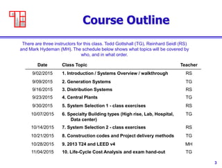
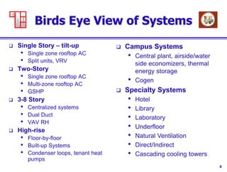
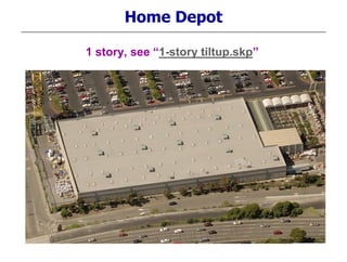
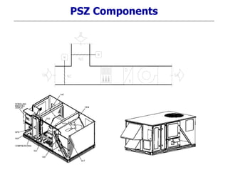
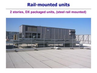
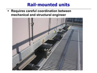
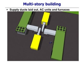
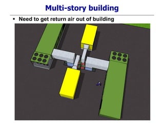
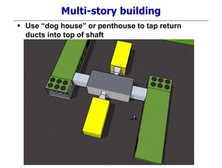
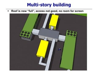
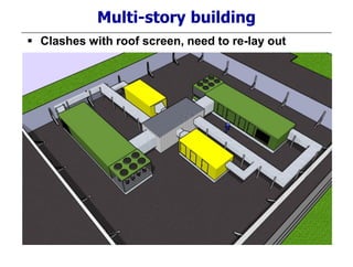
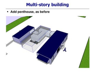
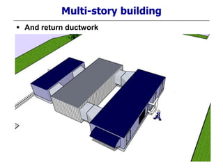
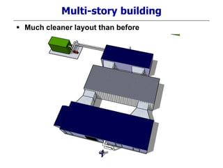
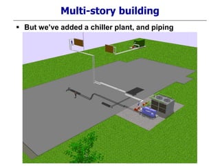
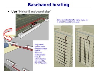
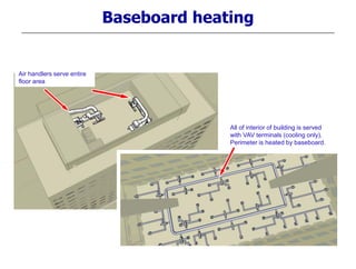
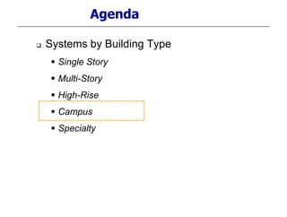
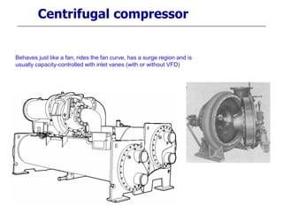
1. X472 HVAC System Design
Considerations
Class 2 – Generation
Systems
Todd Gottshall, PE
Western Allied
Mechanical
Menlo Park, CA
Reinhard Seidl, PE
Taylor Engineering
Alameda, CA
Fall 2015
Mark Hydeman, PE
Continual
San Francisco, CA
2. 2
General
Contact Information
Reinhard: rseidl@taylor-engineering.com
Mark: mhydeman@continual.net
Todd: tgottshall@westernallied.com
Text
• None
Slides
• download from web before class
• Log in to Box at https://app.box.com/login
• Username: x472student@gmail.com
• Password: x472_student (case sensitive)
3. 3
Course Outline
Date Class Topic Teacher
9/02/2015 1. Introduction / Systems Overview / walkthrough RS
9/09/2015 2. Generation Systems TG
9/16/2015 3. Distribution Systems RS
9/23/2015 4. Central Plants TG
9/30/2015 5. System Selection 1 - class exercises RS
10/07/2015 6. Specialty Building types (High rise, Lab, Hospital,
Data center)
TG
10/14/2015 7. System Selection 2 - class exercises RS
10/21/2015 8. Construction codes and Project delivery methods TG
10/28/2015 9. 2013 T24 and LEED v4 MH
11/04/2015 10. Life-Cycle Cost Analysis and exam hand-out TG
There are three instructors for this class. Todd Gottshall (TG), Reinhard Seidl (RS)
and Mark Hydeman (MH). The schedule below shows what topics will be covered by
who, and in what order.
4. 4
Birds Eye View of Systems
Single Story – tilt-up
• Single zone rooftop AC
• Split units, VRV
Two-Story
• Single zone rooftop AC
• Multi-zone rooftop AC
• GSHP
3-8 Story
• Centralized systems
• Dual Duct
• VAV RH
High-rise
• Floor-by-floor
• Built-up Systems
• Condenser loops, tenant heat
pumps
Campus Systems
• Central plant, airside/water
side economizers, thermal
energy storage
• Cogen
Specialty Systems
• Hotel
• Library
• Laboratory
• Underfloor
• Natural Ventilation
• Direct/Indirect
• Cascading cooling towers
10. Small single zone package units
Advantages:
Cheap
Zoning is fairly good by itself
Lightweight
Potentially more efficient than large single zone unit if
programmed / scheduled correctly
Disadvantages
Cheap (Components not high-end, economizers fail)
Service intensive
Not energy efficient if economizer fails or if not scheduled
correctly (both fairly typical)
12. Large single zone package units
Advantages:
Better fan efficiency, economizer (both constant volume, CV
and variable volume, VAV)
Less maintenance
Disadvantages
Heavy !
Much more ductwork than for small packaged units
Large zone doesn’t work for most projects, limited to
warehouses and the like
14. Large multi-zone package units
Advantages:
Better fan efficiency, economizer (typically VAV)
Less maintenance
Good zone control
Disadvantages
Heavy !
Even more ductwork than single-zone large AC
Cost of Boiler and piping for VAV RH system
Cost of air terminal, controls and reheat
16. Split Unit Components
Indoor unit / fancoil unit – exposed, wall-hung – note condensate pump
Concealed, ceiling hung, for ducting Cassette unit, ceiling hung
21. Agenda
Systems by Building Type
Single Story
Multi-Story
High-Rise
Campus
Specialty
22. What did we see in lesson1?
Larger Package units – more concentrated
Need to concentrate on shafts, location
Coordination of units follows shafts
23. Shaft Sizing
Building Design Values
Shaft Airflow 53,920 cfm
Floor Area Served 34,700 ft2
Supply Duct Calc's
Target Top-of-duct friction rate 0.3 in H2O/100 ft
Target maximimum velocity 3500 ft/min
Design top-of-duct friction rate 0.27 in H2O/100 ft
Duct Shape rect
Design top-of-duct velocity 3500 ft/min
Supply Duct Area 15.4 ft2
Supply duct riser taps
Length from riser to shaft wall 12 in
Riser width 60 in
Tap area 5.0 ft2
Free Area Calc's
Target top-of-shaft friction rate 0.050 in H2O/100 ft
Target maximimum velocity 1000 ft/min
Pressurization airflow density 0.15 cfm/ft2
Return Airflow 48,715 cfm
Design top-of-duct friction rate 0.012 in H2O/100 ft
Design top-of-duct velocity 1000 ft/min
Free Area 48.7 ft2
Exhaust Ducts
Target top-of-shaft friction rate 0.10 in H2O/100 ft
Target maximimum velocity 2500 ft/min
Fixtures per floor 10
Airflow per fixture 75
Misc exhaust per floor 100
Number of floors 6
Kitchen exhaust (building total) 0
Exhaust Airflow 5,100 cfm
Exhaust Duct Shape round
Design top-of-duct friction rate 0.086 in H2O/100 ft
Design top-of-duct velocity 1250 ft/min
Exhaust Duct Area 4.1 ft2
Shaft Area
Supply Duct Area (from above) 15.4 ft2
Supply Tap Area (from above) 5.0 ft2
Free Area (from above) 48.7 ft2
Exhaust Duct Area (from above) 4.1
Total area 73.2 ft2
Shaft Width 9 ft
Shaft Width 108 in
Shaft Depth 8.1 ft
Shaft Depth 98 in
Check Figures
shaft area ratio 2.1 ft2
/1000 ft2
airflow density 1.6 cfm/ft2
Proposed Shaft size (inside clear dimensions)
Shaft Width 9.0 ft2
Shaft Depth 8.0 ft2
Safety factor -2%
31. Multi-story building
Location of shafts determines location of duct
risers, and units
Location of steel or concrete beams determine
possible locations of equipment due to weight
Ductwork layout determines if equipment will fit
on roof
37. Multi-story building
Before you start design:
How many shafts are there?
If you choose package units, how many and what size will
you need? Are you limiting yourself to certain manufacturers
because of duct connection locations?
Do you need external ductwork or even external sound
traps? On supply and return or just supply?
Do you want isolation steel curbs or standard curbs?
Make sure the architect knows you need a penthouse – the
mechanical contractor won’t build this.
Push all units around “loosely” before designing too much.
Leave some spare space for filter and fan access, coil pull,
walk ways, and 10-15ft clearance from outside air intakes.
38. Multi-story building
Notes on external ductwork:
External duct is prone to leakage from pooling rainwater
Especially return duct is at risk because of negative pressure
Even some small (cheaper) package units have this problem
48. Package unit limitations
Options to consider:
Outside air intake damper (separate damper, flow measurement
station) for ventilation compliance with Std 62 (LEED projects with
ventilation credit). See also
http://www.energy.ca.gov/title24/2005standards/index.html , go to NR compliance manual
Chapter 4, section 4.3.5 - http://www.energy.ca.gov/2005publications/CEC-400-2005-
006/chapters_4q/4_Mechanical_Systems.pdf
http://nashville.ashraeregion7.org/April%202015%20Bonus%20Material/ASHRAE%202015%20-
RESPONSIBLE%20USE%20OF%20REFRIGERANTS%20IN%20HVAC.ppt
FC fan vs BI fan or plenum fan
Filters – type and depth
Heat recovery – (heat wheel)
Evaporative condenser
Direct or indirect pre-cooler
Blow-through or draw-through fan
Return fan or exhaust fan
Refrigerant
49. Package unit options
Outside air measurement
Integrated into outside air damper (in blades)
Airflow monitoring station (bank of flow crosses from VAV
terminals)
Fan inlet ring
Fixed pitot array
Separate dedicated outside air damper
50. Package unit options
Fan type
See ASHRAE 2004 Systems and Equipment, Chap.18 and
UCB X-470
Forward curved is least efficient but cheapest, limited static
pressure
Backward inclined and Airfoil have highest efficiencies, but
noisier than FC, non-overloading but large surge region
Plenum fan allows flexibility with respect to connections, if
cabinet allows this
All of the above statements on efficiency only true if selected
correctly
51. Package unit limitations
Filters – type and depth
See ASHRAE 2004 Systems and Equipment, Chap.24
Prefer cartridge to bags, don’t sag when full
Pre-filters usually not useful
See http://www.cdc.gov/niosh/docs/2003-136/2003-136c.html
52. Package unit limitations
Why no pre-filters?
They add ~0.25” pressure drop and therefore increase energy usage
They must be replaced 3 to 4 times a year, increasing maintenance costs due
to the cost of the media and labor
They do not improve overall filtration efficiency – they filter out only large
particles that the high efficiency filter is filtering at 99% without any help
ASHRAE studies have shown that filters as they get older can be net
producers of indoor contaminants because dirty filters foster microbial growth,
particularly those in AHUs with outdoor air intakes which often draw in near
saturated air when during cold or foggy or rainy days. The microbes give off
VOCs that detract from indoor air quality. Because of this problem, the
current conventional wisdom is to change filters at least once a year, 18
months tops.
Typical bag and cartridge filters can easily last 18 months without a prefilter,
except perhaps in unusual cases like near a dusty construction site. (Our
experiment below will verify if UCM is “unusual.”)
Hence prefilters only add to energy and maintenance costs yet offer zero
value
53. Package unit options
Energy recovery wheel
Need to balance energy penalty (fan pressure increase)
against reduced coil loads. May not be net gain for mild
climate.
54. Package unit limitations
Evaporative condenser
Increases capacity of condenser by running water spray over
condenser coils. Evaporating water is much more efficient
than air, but requires more maintenance (just like closed
circuit fluid cooler) and water treatment.
55. Package unit limitations
Direct or indirect pre-cooler
Just like evaporative condenser, using water increases
efficiency. Some units allow a retrofit 3rd party cooler to be
mounted.
This works like the Indirect coolers discussed in lesson 1 –
air is pre-cooled by evaporating water indirectly, and reduces
coil load.
56. Package unit limitations
Blow-through or draw-through fan
Blow-through fan does not add its fan heat (usually 2-4°F) to
airstream, since is is upstream of coil.
Draw-through fan gives better airflow distribution across coil
because it is sucking through the coil instead of blowing at it.
57. Package unit limitations
Return fan or exhaust fan
Return fan is more forgiving for high pressure in return duct
(shaft size determines this to a large degree).
Exhaust fan is more efficient because it only moves part of
the airflow (the exhausted part) instead of the entire return air
+ exhaust air flow.
58. Package unit limitations
Refrigerants
Older package units are typically charged with R-22 which is a
hydrochlorofluorocarbon refrigerant (HCFC)
Newer units are equipped with R-410A (typically the smaller units) or
R-407C (typically the larger units), they are hydrofluorocarbons
(HFC’s). These are both zeotropes (the entire 400-series of
refrigerants are zeotropes). This means that the different
components of the refrigerant boil at different temperatures; in case
of a leak, the mixture changes.
See phaseout
timetable:http://www.epa.gov/ozone/title6/phaseout/index.html
And also http://ateam.lbl.gov/coolsense/cases/cfc/index.htm
Class 1 (CFC, incl R-11, R-12) – 1996 production stop,
Class 2 (HCFC, incl R-22) – 2015 production/import stop for new
equipt, 2020 complete stop
HFCs ok – R134a, R407c, R410a
59. Multi-story building
Air handlers are much more flexible than package
units – selection here now has one unit each for
hot deck and cold deck, instead of two units each.
Use “Dual Duct System
AHU.skp”
65. Multi-story building
Custom air handlers themselves are more
expensive than package units.
In addition, we’ve added significant equipment,
piping, design, controls and maintenance costs.
So, for our building, this would not make sense,
unless we had (as an example) a data center in
the lower floor.
66. Large VAV package units vs AHUs
Advantages:
Cheaper than watercooled AHU’s, easier to install than DX
AHU’s
Recently, fairly good efficiencies with evap.condensers and
chemical free water treatment
Disadvantages
Still less efficient than chilled water plant
More maintenance than AHUs (campus system)
Less adaptable, low customization level, can lead to layout
problems
67. Multi-story building
Split units still get used for IT closets, guard
rooms and the like, to maintain 24/7 operation.
It’s worth considering that, with modern package
units and variable speed drives, these rooms can
operate in economizer in the mild CA climate
when connected to the central system.
This is actually more efficient than using split
units.
69. Multi-story building
As an example, let’s use a 75 Hp package unit with
30,000 cfm and a 30 Hp motor.
3 IT rooms are equipped with a 1-ton split unit each,
which runs at a total of 1.5 kW/ton or a total of 4.5 kW
= 6 Hp
The main unit normally runs at 5” TSP, 27,000 cfm,
80% fan eff., for 27,000*5/6356/0.8 = 26.5 Hp.
At night, it runs 60°F air in economizer, or 550 cfm/ton
for 80°F IT rooms.
To move 1650 cfm, the unit requires roughly 0.1” TSP,
or 0.1 Hp. Even if inefficiency of drive and fan rise, it
will be less than the 6 Hp required by split units.
70. Multi-story building
VRV systems
Essentially like split systems, but with the added
advantage of simultaneous heat/cool operation
on multiple fancoils with single condensing unit
Note that, just like with traditional split units,
outside air economizer is lost (or, if installed as
purely theoretically possible, the added
shafts/duct mean you may as well go back to
central units)
71. Multi-story building
VRV systems
Quite a few manufacturers now coming to US,
previously mostly Japan / Europe
Daikin
Fujitsu
Hitachi
Mitsubishi
Toshiba
72. VRV vs Splits
Advantages:
More flexible – longer refrigerant lines, multiple fancoils on
one condensing unit, simultaneous heating/cooling
Better overall energy efficiency (variable speed compressors,
heat regain)
Disadvantages
For some manufacturers, custom piping/engineering must be
done by manufacturer
No airside economizer (big issue for Bay Area)
If trying to do a whole building or high-rise (as advertised),
still end up with “condenser farm”. Also results in large
refrigerant volume within building.
73. Agenda
Systems by Building Type
Single Story
Multi-Story
High-Rise
Campus
Specialty
74. Ground Source Heat Pumps
Advantages:
More constant temperature profile for year-round compressor
efficiency
Better operating cost
Most cost effective in harsh climates
Disadvantages
Higher first cost than package units
Investigate suitability of soils / ground conditions
Need enough space for distribution of loops
Works only for non 24/7 loads, otherwise ground builds
temperature rise over the years (requires annual
heating/cooling load calculations for expected rejection of
cooling load / absorption of heating load)
75. Ground Source Heat Pumps
Methods:
Horizontal or vertical loop distribution
Example below: ~ 500 ft / ton loop run horizontally
Example next page: ~ 20 tons w. 30 loops 300’ deep
76. Ground Source Heat Pumps
Example:
~8,000 sqft building, 20 tons cooling
30 loops, 300 ft deep
77. Ground Source Heat Pumps
Example:
~8,000 sqft building, 20 tons cooling
20 horiz.loops, 500 ft long
78. Agenda
Systems by Building Type
Single Story
Multi-Story
High-Rise
Campus
Specialty
81. Floor-by-floor units
One mech. Room per floor, one large heat pump
Boiler for
VAV
Reheat
Elevator
machine
room unit
Cooling
Towers
Makeup Air
Handler
82. Floor-by-floor units
One mech. Room per floor, one large heat pump
Return Air
Makeup
Air
Supply Air
Supply Air
83. Floor-by-floor units
One mech. Room per floor, one large heat pump
Return Air
Makeup
Air
Supply Air
Supply Air
84. Floor-by-floor units
One mech. Room per floor, water cooled DX AC
unit
Mixed Air through coilSupply Air
85. Floor-by-floor units
One mech. Room per floor, water cooled DX AC
unit
Mixed Air through coil
FAN ARRAY
86. Floor-by-floor units
One mech. Room per floor, one large heat pump
Return Air
Makeup
Air
Supply Air
Supply Air
Floor-by-
floor unit
Supply duct
plenum
87. Floor-by-floor units
One mech. Room per floor, one large heat pump
Return Air
Makeup
Air
Supply Air
CW riser
connection
Floor-by-
floor unit Supply duct
plenum
89. Floor-by-floor units
One mech. Room per floor, one large heat pump
Boiler for
VAV
Reheat
Elevator
machine
room unit
Cooling
Towers
Makeup Air
Handler
Use “Hirise floor by floor AHU.skp”
90. Floor-by-floor AHU’s
One mech. Room per floor, one Air Handler per floor
Boiler for
VAV
Reheat
Elevator
machine
room unit
Cooling
Towers
Makeup Air
Handler
Chiller
91. Floor-by-floor AHU’s
One mech. Room per floor, one Air Handler per floor
Floor-by-floor
unit (“SWUD”)
becomes AHU
WSHP
becomes
fancoil
Condenser water
becomes chilled
water
Note: SWUD unit is not really
industry nomenclature, but an
old Trane model name.
Nevertheless, many people will
know what you mean when
you say SWUD unit.
92. Multi-stage towers
Not common, but in theory allow cooling tower system to
produce water at wetbulb of surrounding air (note – very
similar principle as used in the Coolerado cooler)
Direct 2-stage
93. Multi-stage towers
Not common, but in theory allow cooling tower system to
produce water at wetbulb of surrounding air
Indirect 2-stage
94. Cooling Towers
Stepping out of a
shower when wet, or
out of a pool on a
windy day, cools you
down.
Water which
evaporates off your
skin takes the heat
of evaporation from
your body.
The more wind you
experience, the
more you will cool
down.
The same exact thing
happens in a cooling
tower. Except, the water
which evaporates does
not take its heat from
some other body (there is
none).
Instead, part of the water
evaporates, and takes its
heat from the remaining
water which does not
evaporate. That remaining
water then cools down.
The cooling tower fan
varies the rate of “wind” to
modulate the cooling
effect as needed.
95. Cooling Towers
Stepping out of a
shower when wet, or
out of a pool on a
windy day, cools you
down.
Water which
evaporates off your
skin takes the heat
of evaporation from
your body.
The more wind you
experience, the
more you will cool
down.
The same exact thing
happens in a cooling
tower. Except, the water
which evaporates does
not take its heat from
some other body (there is
none).
Instead, part of the water
evaporates, and takes its
heat from the remaining
water which does not
evaporate. That remaining
water then cools down.
The cooling tower fan
varies the rate of “wind” to
modulate the cooling
effect as needed.
96. Cooling Towers
• ƒThe ambient wet-bulb is a
measure of the humidity. The
higher the wet-bulb, the more
humid the air.
• ƒWet-bulb temperature can never
exceed dry-bulb temperature.
• ƒDry-bulb temperature is what
we commonly refer to as just
temperature
• ƒThe leaving water temperature
of the cooling tower can never
be less than the wet-bulb
temperature of the entering air.
97. Cooling Towers
• ƒƒRANGE: entering water temperature –
leaving water temperature. In this
example: 90°F 80°F = 10°F
• ƒAPPROACH: difference between
leaving water temperature and
ambient wet-bulb temperature. In this
example: 80°F – 62°F = 18°F
• ƒThe closer the approach, the more fan
energy the tower will require, and the
larger its surface will have to be
• Rejected Heat in tons = Flow rate
(gpm) * Range (°F) * 500 / 12000
(Btu/hr)
• Sometimes, calculations for towers are
done by dividing by 15,000 Btu/hr to
equate to chiller tons rejected
98. Cooling Towers
• ƒƒExample:
• Range = 90°F - 80°F = 10°F
• Flow Rate: 100 gpm
• Rej. Heat: 10 * 100 * 500/12000 = 41.6
tons
• Equivalent roughly to a connected chiller of
• CT tons: 10 * 100 * 500/15000 = 33.3 tons
• The 15,000 Btu/h factor includes roughly 30%
for chiller motor heat
• Important to remember which tonnage you’re
talking about, and always better to give range
and flow rate than “tons” because those are not
subject to interpretation
99. 99
120 tons capacity, low airflow
Dh
Dh * tower airflow (lbs/h) = cooling tower capacity (Btu/h)
Example:
Flow = 160 gpm
Range = 18°F
Capacity =160*18*500/12000 =
= 120 tons
Airside flow has to be:
h1=(62° wb) = 27.7 Btu/lb
h2=(70° wb) = 34.1 Btu/lb
F=120 tons/Dh = 3,756 lbs/min
Density r @ Ta,in = 0.0728 lb/ft3
Airflow = F/r = 51,590 cfm
Tw,in=84°FTw,out=66°F
Range=18°F
Approach=4°F
Ta,in=83/62°F
Ta,out=70/70°F
Conditions
of air
Conditions
of water
100. 100
120 tons capacity, higher airflow
Dh
Dh * tower airflow (lbs/h) = cooling tower capacity (Btu/h)
Example:
Flow = 160 gpm
Range = 18°F
Capacity =160*18*500/12000 =
= 120 tons
Airside flow has to be:
h1=(62° wb) = 27.7 Btu/lb
h2=(68° wb) = 32.4 Btu/lb
F=120 tons/Dh = 5,085 lbs/min
Density r @ Ta,in = 0.0728 lb/ft3
Airflow = F/r = 69,845 cfm
Tw,in=84°FTw,out=66°F
Range=18°F
Approach=4°F
Ta,in=83/62°F
Ta,out=68/68°F
Conditions
of air
Conditions
of water
101. 101
Cooling tower – basic operation
Closed tower (or closed circuit fluid
cooler): a closed coil isolates the
cooling water from the water, circulated
through the tower.
This means less problems with water
treatment for coils served by cooling
water
Range and approach definitions remain
the same
A closed circuit tower will be less
effective (greater fan energy per unit of
cooling) than an open tower at the
same size
102. Types of Cooling Towers
Cooling towers
Open, axial counter-flow towers most efficient
Cross-flow towers for special space
arrangements
Centrifugal towers for installation inside building
envelope, or for low profile, but not efficient
103. Cooling Towers
• Towers come in different models, although they all share the
same exact basic mechanism.
• The differences are mainly dictated by their physical installation
parameters, such as
• Low height (which requires a low profile tower) usually comes
with inefficient centrifugal blow-through fans (prohibited by T24 >
900 gpm at std ARI rating conditions)
• Backing the tower against a retaining wall or building wall means
only a single inlet can be used, which is less efficient than a dual
inlet
• Best efficiency overall comes from counterflow towers with axial
draw-through fans (most common model)
• The T24 efficiency of cooling towers is expressed in gpm/motor
Hp with water temperatures at standard ARI rating conditions
(95F to 85F water at 75F wetbulb)
107. Cooling Tower Water Treatment
Water treatment
Chemical
Biocide prevents growth of bacteria.
Acid prevents scale formation, but corrodes tower.
Corrosion inhibitor then fights corrosion effect
All have to be measured out correctly, and vary with cycles of
concentration.
108. Cooling Tower Water Treatment
Water treatment
1
)(
)()(
ionconcentratofCycles
gpmnEvaporatio
gpmWindagegpmRateBleed
-
20.00
40.00
60.00
80.00
100.00
120.00
140.00
160.00
1.00 1.50 2.00 2.50 3.00 3.50 4.00 4.50 5.00
Cycles of Concentration
Totalmakeup,GPM
See spreadsheet in lesson 2
handouts for calculation method.
109. Cooling Tower Water Treatment
Test rack (coupons) chemical feed pumps and controller … and chemicals
110. Cooling Tower Water Treatment
Alternative: new cleaning methods based on
magnetic fields or high-impact vortex
Pulsed magnetic field in flow tube
Cavitation chamber
111. Cooling Tower Review
Tutorial on multiple, staged towers
See PDF from additional lesson 2 handouts
Multiple staged towers allow cooling below the dewpoint
Can be useful when this avoids buying a chiller plant (see
discussions of data center cooling in lesson 6)
Water treatment
Chemical
Non-Chemical
112. Tower sizing
Tower efficiency:
Typical sizing is for 95°-85°F water, 70°F
Ambient wb.
This results in a “typical” tower size.
Doubling tower size results in ¼ of fan
energy for same conditions. In practice, this
means running as many tower cells as
possible.
Will come back to this topic in LCC chapter
113. Open vs closed vs evap condenser
Open towers – highest efficiency
Closed circuit cooler – keeps condenser
water clean in a separate circuit – more
expensive, and less efficient, but for small
sizes better than open tower with heat
exchanger
Evaporative condenser – more efficient than
additional water – circuit for heat transfer.
Not common in HVAC applications, more
industrial.
115. Induction Units and Fancoil Units
Note: no ceiling diffusers in the
exterior spaces at all.
Use “Hirise Induction.skp”
116. Induction Units and Fancoil Units
Ductwork and piping runs
along exterior of building shell
(between windows).
Note: This scheme can apply
equally well to baseboard heat
(without ductwork)
118. Induction Units and Fancoil Units
Note: the tempering station typically occurs when condensate
drains are left out of the induction unit/fancoil unit installation.
Often, this was done in induction unit systems.
This has the advantage of reducing cost, but the disadvantage
of reducing unit capacity, since water now has to be provided
above the space dewpoint to prevent the cooling coils from
condensing water out of the airstream.
Makeup fan (DOAS, dedicated outside air system) and Chilled
water tempering station
Tempering station increases
chilled water temperature by
re-circulating part of the
return water into the supply
119. Induction Units and Fancoil Units
Interior Air Handlers (built-
up) serve interior zones
Interior of building is served with
VAV terminals (cooling only or with
reheat), exterior served by fancoils
or induction units
120. Induction Units and Fancoil Units
Exterior Air Handlers
(built-up, DOAS) serve
exterior zones
Interior of building is served with
VAV terminals (cooling only or with
reheat), exterior served by fancoils
or induction units
121. Induction Units and Fancoil Units
Interior Air
Handlers (built-
up)
Exterior Air Handlers (built-up)
123. Basebaord heating
Very similar
system to the
fancoil/induction
system
discussed
earlier, except
here, the
external zones
are served by
the VAV system
Same considerations for piping layout as
in fancoil / induction unit case:
Use “Hirise Baseboard.skp”
124. Baseboard heating
Air handlers serve entire
floor area
All of interior of building is served
with VAV terminals (cooling only).
Perimeter is heated by baseboard.
129. Agenda
Systems by Building Type
Single Story
Multi-Story
High-Rise
Campus
Specialty
130. Chilled water plants
Chiller plant
Air-cooled
2005 T24: for plants with more than 300 tons capacity, only 100 tons
can be aircooled
Watercooled
135. Reciprocating compressor
Looks a little like the engine
of your car, and works in the
same in reverse – shaft is
driven, and the gas in the
cylinders is compressed
138. Centrifugal compressor
Behaves just like
a fan, rides the
fan curve, has a
surge region and
is usually
capacity-
controlled with
inlet vanes (with
or without VFD)
139. Centrifugal compressor
Behaves just like a fan, rides the fan curve, has a surge region and is
usually capacity-controlled with inlet vanes (with or without VFD)
142. Chiller size
5 10 100 500 1,000 5,000 10,000
Recip
Scroll
Screw
Centrifugal
Absorption
Capacity, Tons
Choice of compressor type depends on capacity
143. Agenda
Systems by Building Type
Single Story
Multi-Story
High-Rise
Campus
Specialty
144. Firetube
Typically more mass
Slower response
More tolerance for flow
fluctuations
Dry-back and wet-back
Watertube
Typ. Less mass
Mostly used for older “BBQ”
style atmospheric boilers
Boilers
Tubes left out for
clarity. Blue = water
filled volume
145. Atmospheric boilers
“Old style”, typically water tube for commercial HW applications
High NOx emissions due to inaccurate combustion control (BBQ)
Typically just 2:1 turndown (gas valve = off / low / high fire)
Typically Cu-finned heat exchanger
Forced Draft and condensing boilers
Forced draft required to meet Low NOx ratings
Very large price increase over atmospheric boilers
Now have controlled combustion, often with VFD blower and modulating
gas valve
Condensing boilers add more efficiency by allowing cold water to enter
heat exchanger; this causes (acidic) combustion products to condense in
HX and in flue, so these need to be corrosion resistant; Typical category
IV flues are SS (AL29-4C) and heat exchangers are typically SS,
Aluminum or Cast Iron.
Dual HX boilers (one condensing, the other non-condensing) typically do
not work as “real” condensing boilers and are not recommended
Boilers
146. BAAQMD
Bay Area Air Quality Management District, see regulation 9 rule 6 at
http://www.baaqmd.gov/?sc_itemid=D39A3015-453E-4A0D-9C76-
6F7F4DA5AED5
Page 3 and 4 of 5 show NOx limits per boiler size and implementation
deadlines
Boilers
147. BAAQMD
Bay Area Air Quality Management District, see regulation 9 rule 7 at
http://www.baaqmd.gov/?sc_itemid=D39A3015-453E-4A0D-9C76-
6F7F4DA5AED5
Page 6 and 7 of 11 show NOx limits per boiler size and implementation
deadlines
Boilers
148. Condensing boilers
(inherently Low Nox)
High efficiency but not
condensing boilers (also Low
Nox but not quite as efficient
as condensing)
Look very similar, both have
forced draft burner sections
Add’l cost for condensing
boilers comes from corrosion
resistant materials for HX
material
Much smaller than traditional
boilers ~ 3,000 kBtu/hr model
will typically fit through a
door
Boilers
149. Different flue types now apply
as well, since most
condensing and high
efficiency boilers feature
positive pressure flues (class
III and IV) which cannot be
the old B-type bayonet
couplings, since they are not
pressure tight
In addition, condensing flues
(type II and IV) cannot be
made of galvanized steel,
since that is not corrosion
resistant to the acid inherent
in flue gas condensate (must
be PVC or SS)
Boiler flues
150. Condensing boilers
Things to look for: heat exchanger material, high turndown (5:1 not really
high, think of 10:1 to 25:1 as high) to reduce low load cycling, VFD blower
fan, air shutoff controls, high max dT (ranges from 32° to 170°), low water
dp (ranges from 1 to 25 ft), high press rating (ranges 30psi to 160 psi),
warranty (1 year to 12 years, pro-rated and non-prorated, HX and entire
boiler)
Look for boilers that don’t require re-circ pump and can work in primary only
systems to keep entering water cold and boiler condensing
Boiler types: all represented
Example watertube: Bryan Triple Flex, Hamilton EVO, Lochinvar Sync
Firetube: Buderus SB615, Aerco BMK, Cleaver Brooks Clearfire, Lochinvar
Crest
Plate or sectional Hx: Viessman Vitocrossal, PK Mach, de Dietrich GAS310,
Hyrdrotherm KN, Weil McLean UG3
Boilers