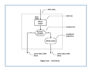
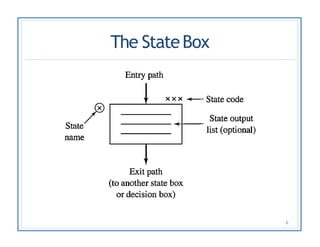
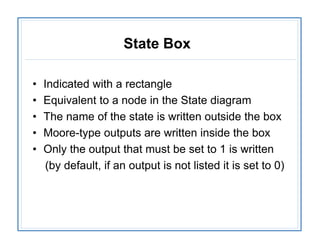
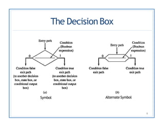
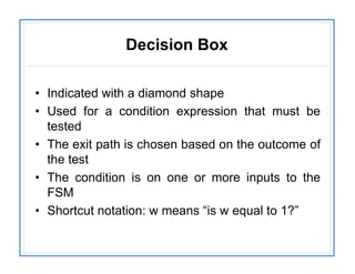
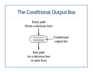
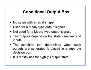
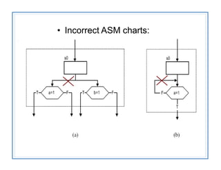
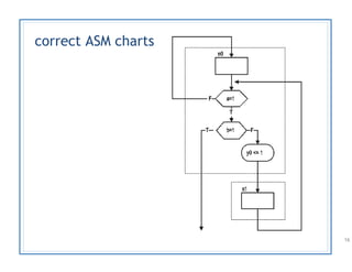
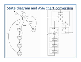
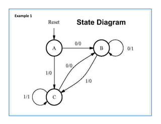
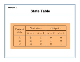
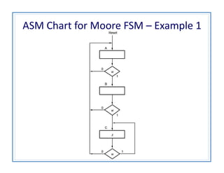
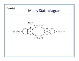
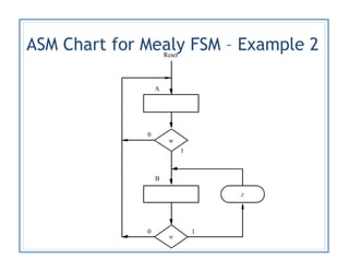
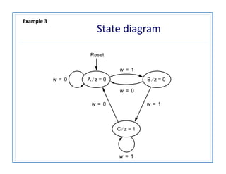
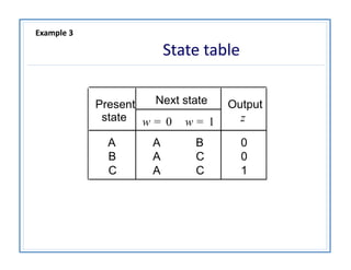
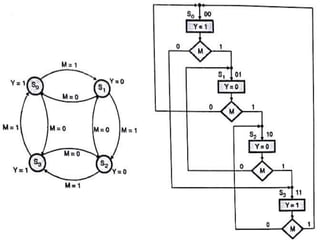
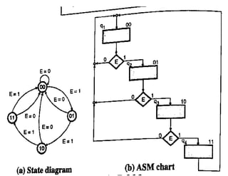
FSM and ASM Charts
1
o FINITE STATE MACHINE
o ALGORITHMIC STATE MACHINE
BY UNSA SHAKIR
Finite State Machine
•A finite-state machine (FSM) or finite-state
automaton is a mathematical model of
computation.
• We have a fixed set of states that the machine can
be in
•The machine can only be in one state at a time
•A sequence of inputs is sent to the machine
•Every state has a set of transitions and every
transition is associated with an input and pointing
to a state
ASM (algorithmic state machine)
– Flowchart-like diagram
– Algorithmic State Machine are suitable for FSMs with a
larger number of inputs and outputs compared to FSMs
expressed using state diagrams and state tables.
– Provide the same information as an FSM
– More descriptive, better for complex
description
– algorithm = sequencing + data manipulation
– Algorithmic state machines can model both
Mealy and Moore Finite State Machines
Algorithmic StateMachines
4
• ASMs have three types of building blocks:
– State Box
– Decision Box
– Conditional Output Box
The StateBox
6
State Box
• Indicated with a rectangle
• Equivalent to a node in the State diagram
• The name of the state is written outside the box
• Moore-type outputs are written inside the box
• Only the output that must be set to 1 is written
(by default, if an output is not listed it is set to 0)
The DecisionBox
Symbol
8
Alternate Symbol
Decision Box
• Indicated with a diamond shape
• Used for a condition expression that must be
tested
• The exit path is chosen based on the outcome of
the test
• The condition is on one or more inputs to the
FSM
• Shortcut notation: w means “is w equal to 1?”
The Conditional OutputBox
1
0
Conditional Output Box
• Indicated with an oval shape
• Used for a Mealy-type output signals
• Not used for a Moore-type output signals
• The outputs depend on the state variables and
inputs
• The condition that determines when such
outputs are generated is placed in a separate
decision box
• It is mostly use for high (1) output state.
talarico@gonzaga.edu 12
talarico@gonzaga.edu 13
Another Loopingexample
01
S0
X
CX
X
CX
01
S0
14
• Incorrect ASM charts:
correct ASM charts
16
State diagram and ASM chart conversion
State Diagram
Example 1
State Table
Example 1
ASM Chart for Moore FSM – Example 1
A
w 0= z 0=
w 1= z 1=Bw 0= z 0=
Reset
w 1= z 0=
Mealy State diagram
Example 2
ASM Chart for Mealy FSM – Example 2
State diagram
C z 1=
Reset
B z 0=A z 0=w 0=
w 1=
w 1=
w 0=
w 0= w 1=
Example 3
Present Next state Output
state w = 0 w = 1 z
A A B 0
B A C 0
C A C 1
State table
Example 3
practice
• Design an FSM that detects if the previous two
values of the input w were equal to 00 or 11
• If either condition is true then the output z should be
set to 1; otherwise to 0.
• Implement this as a Mealy-type machine

FSM and ASM

  • 1.
    FSM and ASMCharts 1 o FINITE STATE MACHINE o ALGORITHMIC STATE MACHINE BY UNSA SHAKIR
  • 2.
    Finite State Machine •Afinite-state machine (FSM) or finite-state automaton is a mathematical model of computation. • We have a fixed set of states that the machine can be in •The machine can only be in one state at a time •A sequence of inputs is sent to the machine •Every state has a set of transitions and every transition is associated with an input and pointing to a state
  • 3.
    ASM (algorithmic statemachine) – Flowchart-like diagram – Algorithmic State Machine are suitable for FSMs with a larger number of inputs and outputs compared to FSMs expressed using state diagrams and state tables. – Provide the same information as an FSM – More descriptive, better for complex description – algorithm = sequencing + data manipulation – Algorithmic state machines can model both Mealy and Moore Finite State Machines
  • 4.
    Algorithmic StateMachines 4 • ASMshave three types of building blocks: – State Box – Decision Box – Conditional Output Box
  • 6.
  • 7.
    State Box • Indicatedwith a rectangle • Equivalent to a node in the State diagram • The name of the state is written outside the box • Moore-type outputs are written inside the box • Only the output that must be set to 1 is written (by default, if an output is not listed it is set to 0)
  • 8.
  • 9.
    Decision Box • Indicatedwith a diamond shape • Used for a condition expression that must be tested • The exit path is chosen based on the outcome of the test • The condition is on one or more inputs to the FSM • Shortcut notation: w means “is w equal to 1?”
  • 10.
  • 11.
    Conditional Output Box •Indicated with an oval shape • Used for a Mealy-type output signals • Not used for a Moore-type output signals • The outputs depend on the state variables and inputs • The condition that determines when such outputs are generated is placed in a separate decision box • It is mostly use for high (1) output state.
  • 12.
  • 13.
  • 14.
  • 15.
  • 16.
  • 17.
    State diagram andASM chart conversion
  • 18.
    State diagram andASM chart conversion
  • 19.
  • 20.
  • 21.
    ASM Chart forMoore FSM – Example 1
  • 22.
    A w 0= z0= w 1= z 1=Bw 0= z 0= Reset w 1= z 0= Mealy State diagram Example 2
  • 23.
    ASM Chart forMealy FSM – Example 2
  • 24.
    State diagram C z1= Reset B z 0=A z 0=w 0= w 1= w 1= w 0= w 0= w 1= Example 3
  • 25.
    Present Next stateOutput state w = 0 w = 1 z A A B 0 B A C 0 C A C 1 State table Example 3
  • 31.
    practice • Design anFSM that detects if the previous two values of the input w were equal to 00 or 11 • If either condition is true then the output z should be set to 1; otherwise to 0. • Implement this as a Mealy-type machine