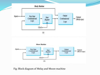
Melay and Moore machine
E.SWAPNA
Assistant Professor
Subject Name: Digital System Design
Academic Year 2020-21 ,II B.Tech I sem , ECE B
Mealy and Moore Models
2
• The most general model of a sequential circuit has inputs, outputs, and internal
states
•. It is customary to distinguish between two models of sequential circuits:
the Mealy model and the Moore model
• They differ in the way the output is generated.
- In the Mealy model, the output is a function of both the present state and input.
- In the Moore model, the output is a function of the present state only.
Fig: Block diagram of Melay and Moore machine
Mealy and Moore Models
4
When dealing with the two models, some books and other technical sources refer to a
sequential circuit as a finite state machine abbreviated FSM.
- The Mealy model of a sequential circuit is referred to as a Mealy FSM or Mealy
machine.
- The Moore model is refereed to as a Moore FSM or Moore machine.
Example of Melay machine in Fig a
Output y is a function of both input x and the present state
of A and B .
Fig b shows state diagram , both the input and output values,
separated by a slash along the directed lines between the states.
Example of Moore machine. Here, the output is a function of the present
state only.
The corresponding state diagram in Fig. b. has only inputs marked
along the directed lines. The outputs are the flip-flop states marked
inside the circles.
The output depends only on flip-flop values, and that makes it a function
of the present state only. The input value in the state diagram is labeled
along the directed line, but the output value is indicated inside the circle
together with the present state.
 In a Moore model, the outputs of the sequential circuit are synchronized
with the clock, because they depend only on flip-flop outputs that are
synchronized with the clock.
 In a Mealy model, the outputs may change if the inputs change during
the clock cycle. Moreover, the outputs may have momentary false values
because of the delay encountered from the time that the inputs change and
the time that the flip-flop outputs change.
 In order to synchronize a Mealy-type circuit, the inputs of the sequential
circuit must be synchronized with the clock and the outputs must be
sampled immediately before the clock edge. The inputs are changed at the
inactive edge of the clock to ensure that the inputs to the flip-flops stabilize
before the active edge of the clock occurs. Thus,
the output of the Mealy machine is the value that is present immediately
before the active edge of the clock.
Moore Machine –
• Output depends only upon present state.
• If input changes, output does change.
• More number of states are required.
• There is less hardware requirement for circuit implementation.
• They react slower to inputs(One clock cycle later).
• Synchronous output and state generation.
• Output is placed on states.
• Easy to design.
Mealy Machine –
• Output depends on present state as well as present input.
• If input changes, output also changes.
• Less number of states are required.
• There is more hardware requirement for circuit implementation.
• They react faster to inputs.
• Asynchronous output generation.
•Output is placed on transitions.
•It is difficult to design.
Moore state graph:
10
Moore state table
11
Present state Input Next state output
A B W Z
0 0 0 0 0 0
0 0 1 0 1 0
0 1 0 1 0 0
0 1 1 0 1 0
1 0 0 0 0 1
1 0 1 0 0 1
1 1 0 x x 0
1 1 1 x x 0
Moore maps
12
Moore circuit diagram:
13
Mealy state graph
14
Mealy state table
15
Present state Input Next state output
A B W Z
0 0 0 0 0 0
0 0 1 0 1 0
0 1 0 1 0 1
0 1 1 0 1 0
1 0 0 0 0 0
1 0 1 0 0 1
1 1 0 x x 0
1 1 1 x x 0
Mealy circuit diagram
16

melay and moore machine.pptx

  • 1.
    Melay and Mooremachine E.SWAPNA Assistant Professor Subject Name: Digital System Design Academic Year 2020-21 ,II B.Tech I sem , ECE B
  • 2.
    Mealy and MooreModels 2 • The most general model of a sequential circuit has inputs, outputs, and internal states •. It is customary to distinguish between two models of sequential circuits: the Mealy model and the Moore model • They differ in the way the output is generated. - In the Mealy model, the output is a function of both the present state and input. - In the Moore model, the output is a function of the present state only.
  • 3.
    Fig: Block diagramof Melay and Moore machine
  • 4.
    Mealy and MooreModels 4 When dealing with the two models, some books and other technical sources refer to a sequential circuit as a finite state machine abbreviated FSM. - The Mealy model of a sequential circuit is referred to as a Mealy FSM or Mealy machine. - The Moore model is refereed to as a Moore FSM or Moore machine.
  • 5.
    Example of Melaymachine in Fig a Output y is a function of both input x and the present state of A and B . Fig b shows state diagram , both the input and output values, separated by a slash along the directed lines between the states.
  • 6.
    Example of Mooremachine. Here, the output is a function of the present state only. The corresponding state diagram in Fig. b. has only inputs marked along the directed lines. The outputs are the flip-flop states marked inside the circles.
  • 7.
    The output dependsonly on flip-flop values, and that makes it a function of the present state only. The input value in the state diagram is labeled along the directed line, but the output value is indicated inside the circle together with the present state.
  • 8.
     In aMoore model, the outputs of the sequential circuit are synchronized with the clock, because they depend only on flip-flop outputs that are synchronized with the clock.  In a Mealy model, the outputs may change if the inputs change during the clock cycle. Moreover, the outputs may have momentary false values because of the delay encountered from the time that the inputs change and the time that the flip-flop outputs change.  In order to synchronize a Mealy-type circuit, the inputs of the sequential circuit must be synchronized with the clock and the outputs must be sampled immediately before the clock edge. The inputs are changed at the inactive edge of the clock to ensure that the inputs to the flip-flops stabilize before the active edge of the clock occurs. Thus, the output of the Mealy machine is the value that is present immediately before the active edge of the clock.
  • 9.
    Moore Machine – •Output depends only upon present state. • If input changes, output does change. • More number of states are required. • There is less hardware requirement for circuit implementation. • They react slower to inputs(One clock cycle later). • Synchronous output and state generation. • Output is placed on states. • Easy to design. Mealy Machine – • Output depends on present state as well as present input. • If input changes, output also changes. • Less number of states are required. • There is more hardware requirement for circuit implementation. • They react faster to inputs. • Asynchronous output generation. •Output is placed on transitions. •It is difficult to design.
  • 10.
  • 11.
    Moore state table 11 Presentstate Input Next state output A B W Z 0 0 0 0 0 0 0 0 1 0 1 0 0 1 0 1 0 0 0 1 1 0 1 0 1 0 0 0 0 1 1 0 1 0 0 1 1 1 0 x x 0 1 1 1 x x 0
  • 12.
  • 13.
  • 14.
  • 15.
    Mealy state table 15 Presentstate Input Next state output A B W Z 0 0 0 0 0 0 0 0 1 0 1 0 0 1 0 1 0 1 0 1 1 0 1 0 1 0 0 0 0 0 1 0 1 0 0 1 1 1 0 x x 0 1 1 1 x x 0
  • 16.