Downloaded 802 times
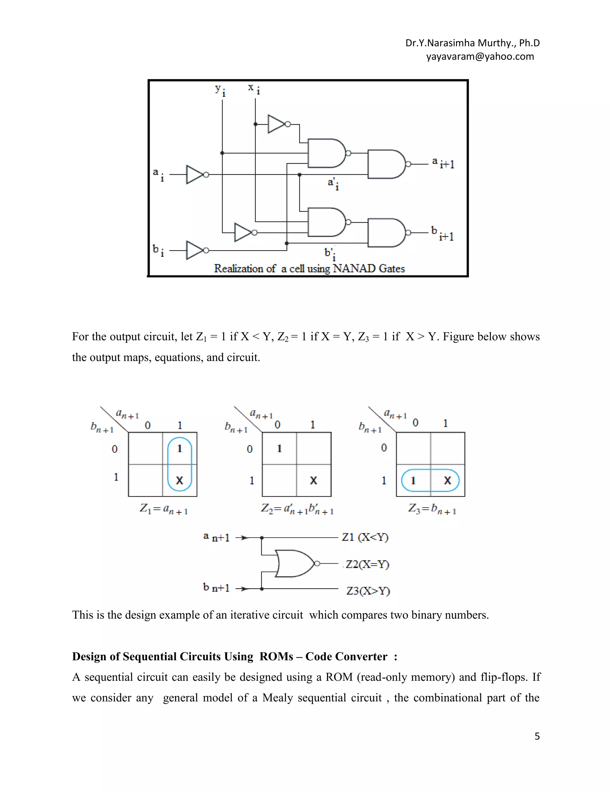
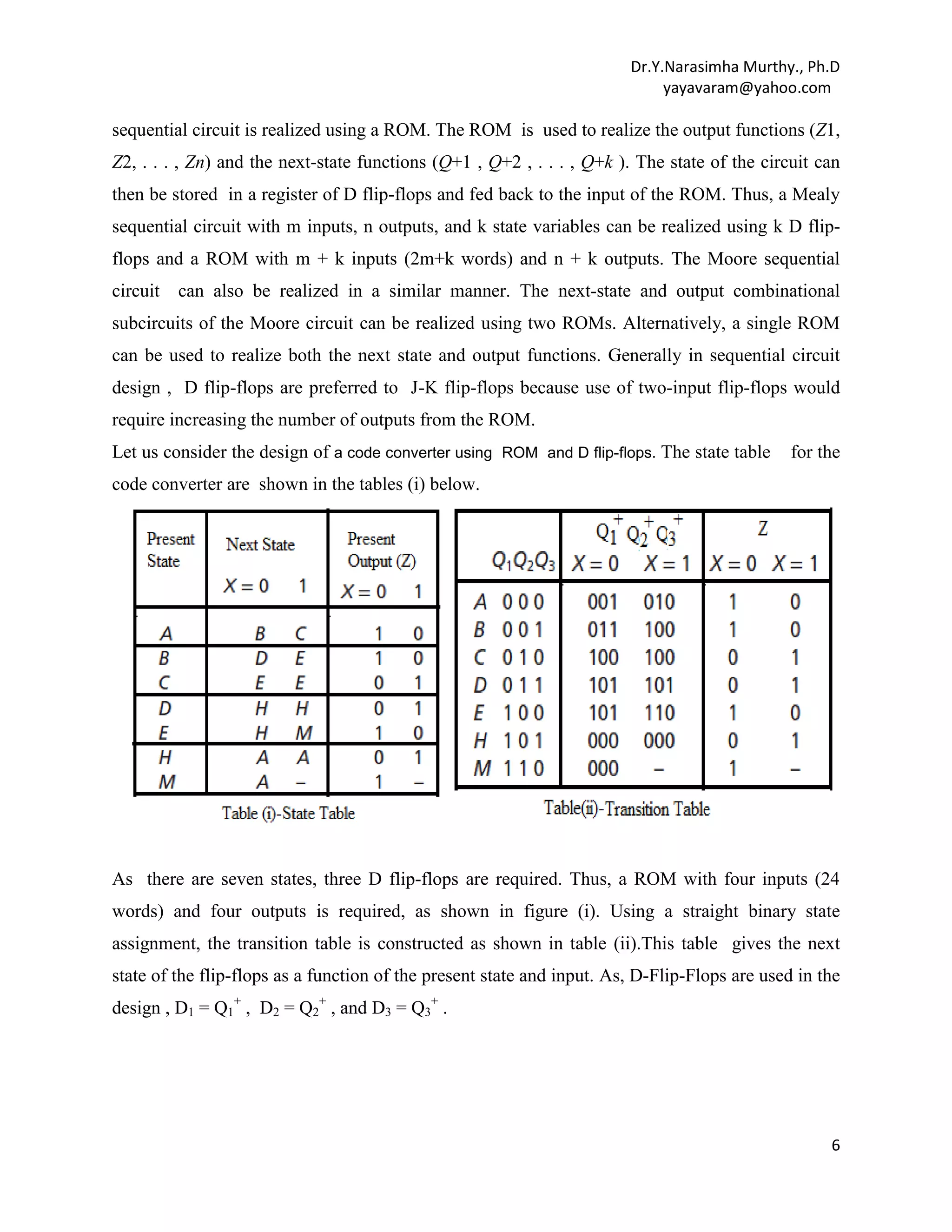
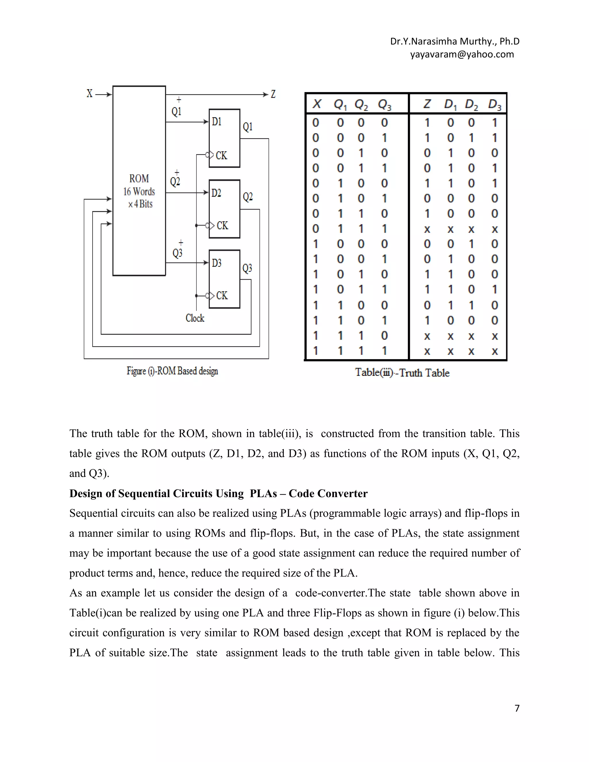
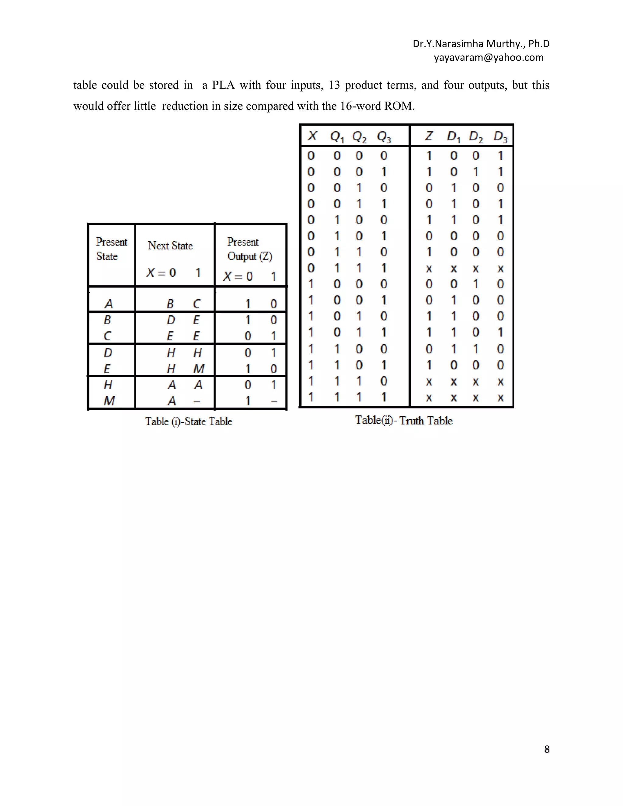
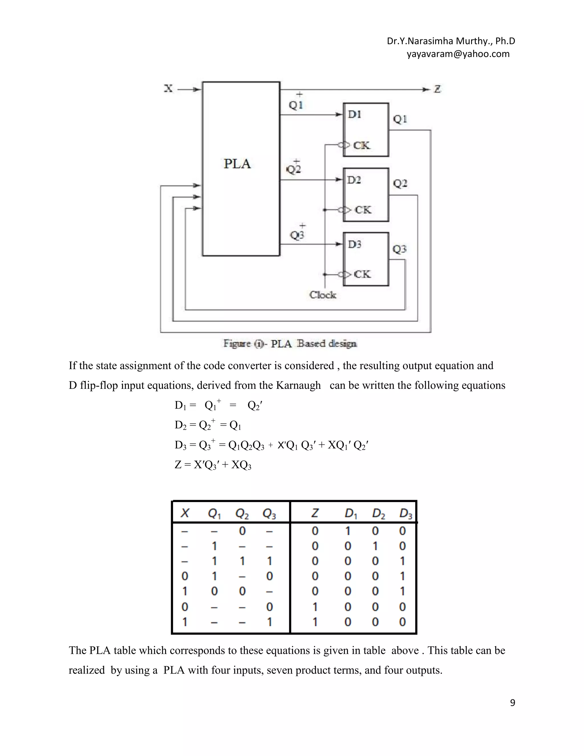
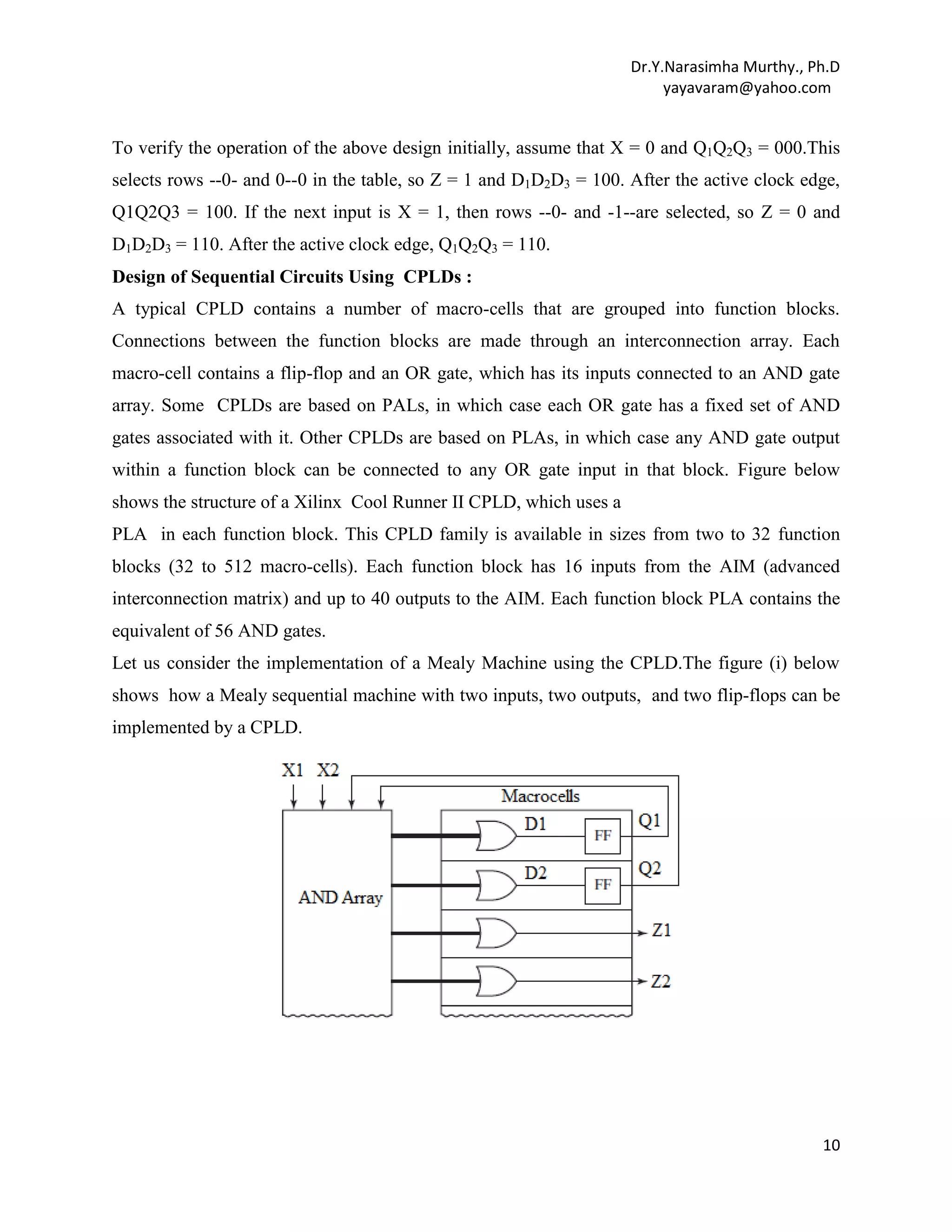
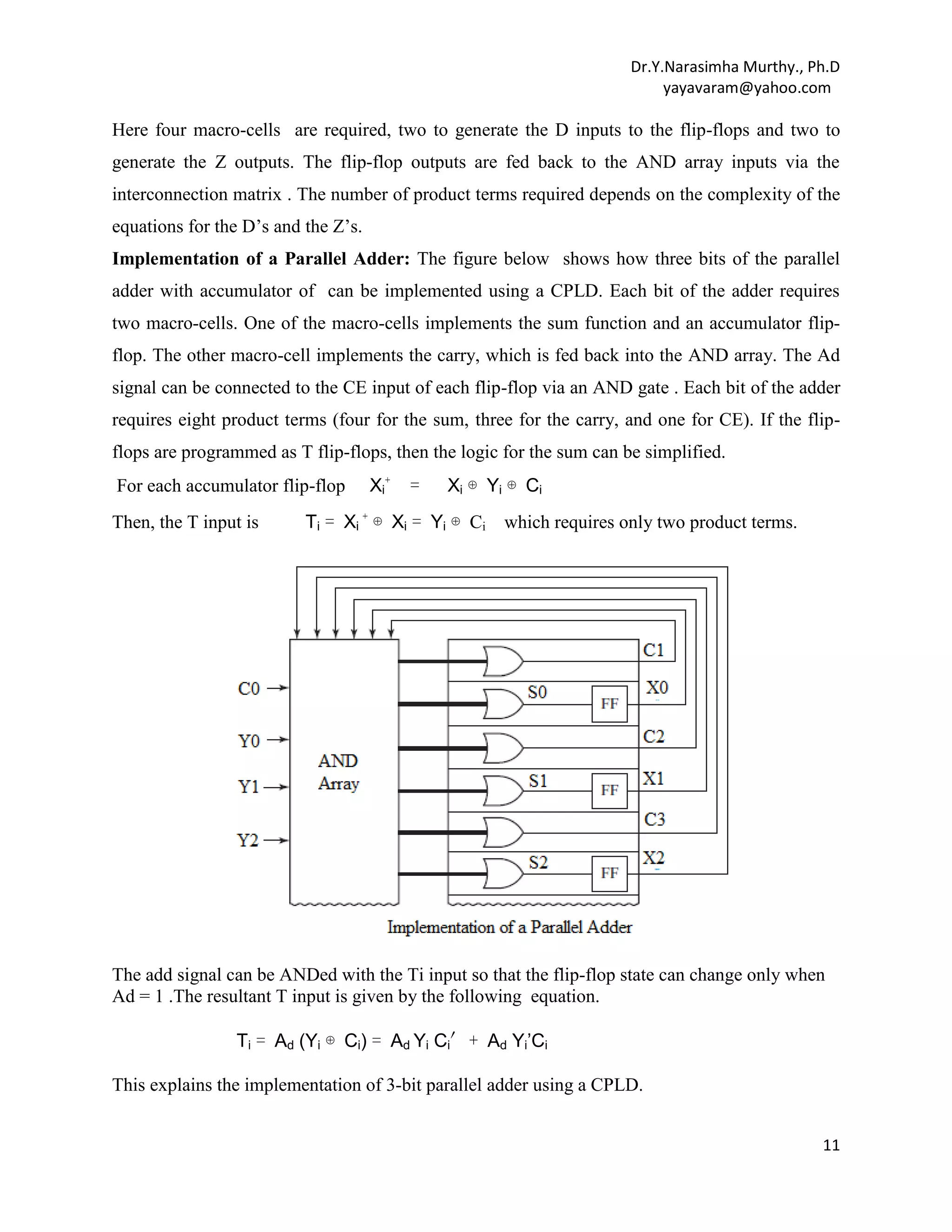
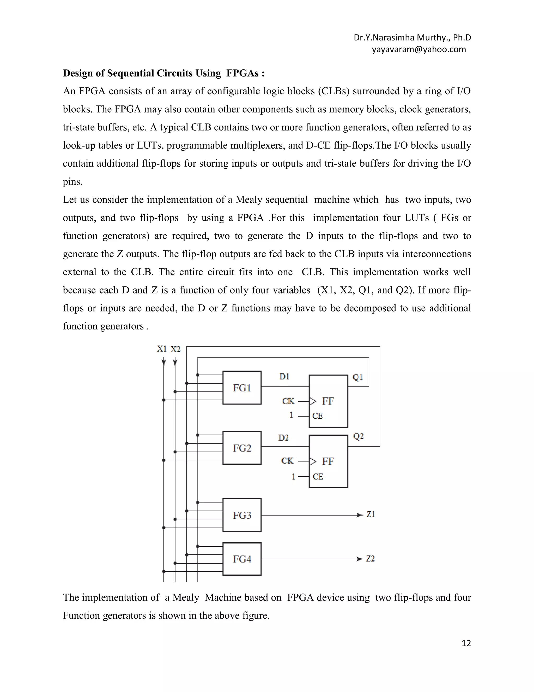
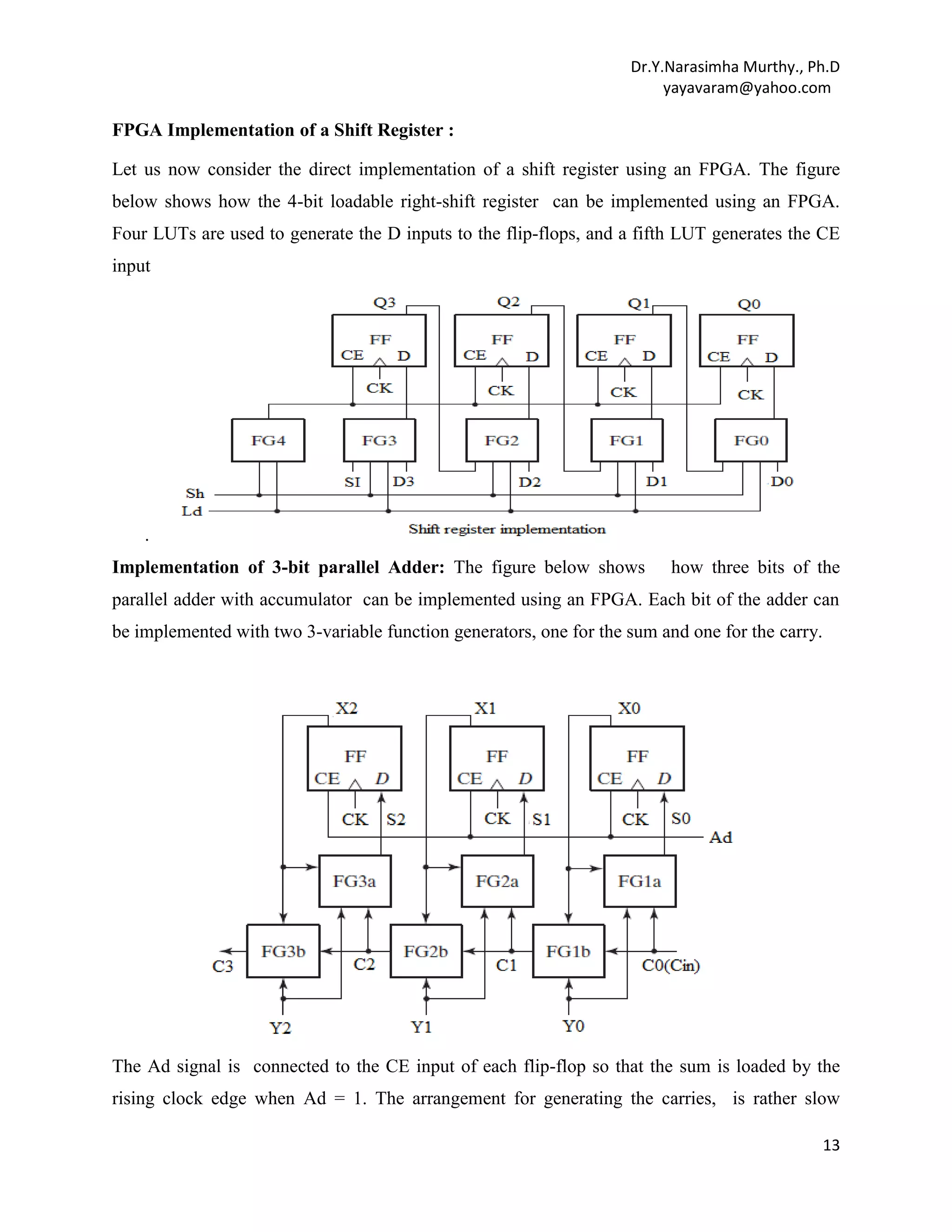
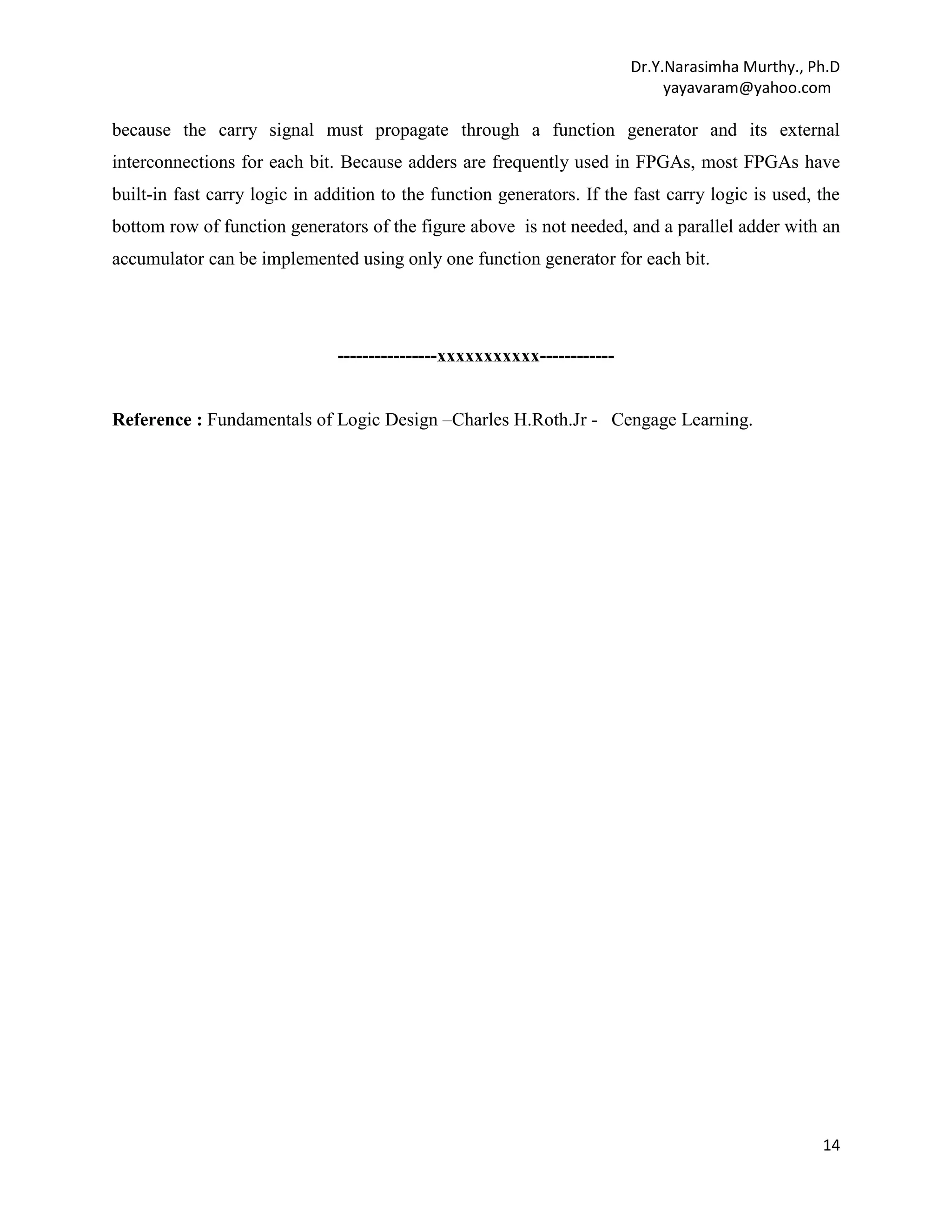

This document discusses several methods for designing sequential circuits, including state table reduction, state assignment, derivation of flip-flop input equations, and realization using logic gates. It provides an example of designing a comparator circuit using an iterative approach with identical cells. The document also describes implementing sequential circuits using ROMs, PLAs, CPLDs and FPGAs, giving examples of a code converter and parallel adder circuit designs for each method.


![Coded Agents – with UiPath SDK + LangGraph [Virtual Hands-on Workshop]](https://cdn.slidesharecdn.com/ss_thumbnails/codedagentsdeck-251215155422-5497c599-thumbnail.jpg?width=640&height=640&fit=bounds)


