Download as PDF, PPTX
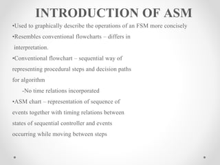
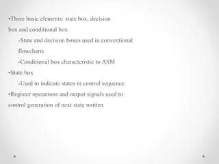
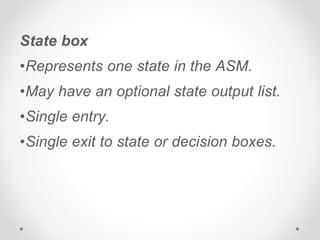
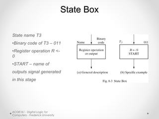
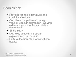
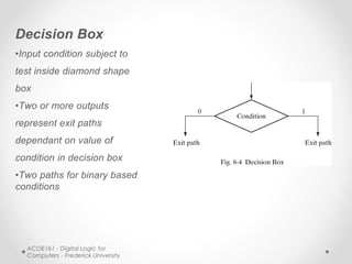
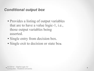
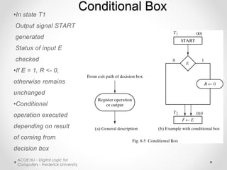
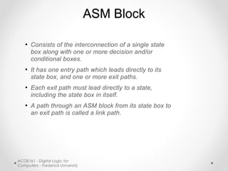
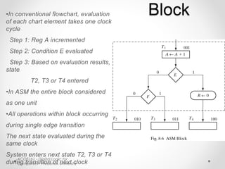
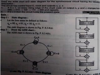
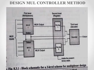
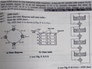
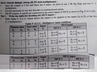
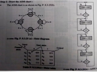
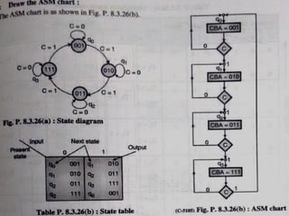

This document introduces the basics of asynchronous sequential machine (ASM) notation for describing finite state machines: - ASM uses state boxes, decision boxes, and conditional boxes to graphically describe the operations of a finite state machine more concisely than conventional flowcharts. State boxes indicate states, decision boxes represent conditional transitions between states, and conditional boxes list outputs. - An ASM block consists of interconnecting a single state box with decision and/or conditional boxes, representing the operations that occur within a single clock cycle as the system enters the next state. All elements within the block are evaluated simultaneously. - Timing considerations require that all sequential elements be controlled by a master clock, though multiple clocks can