Downloaded 97 times
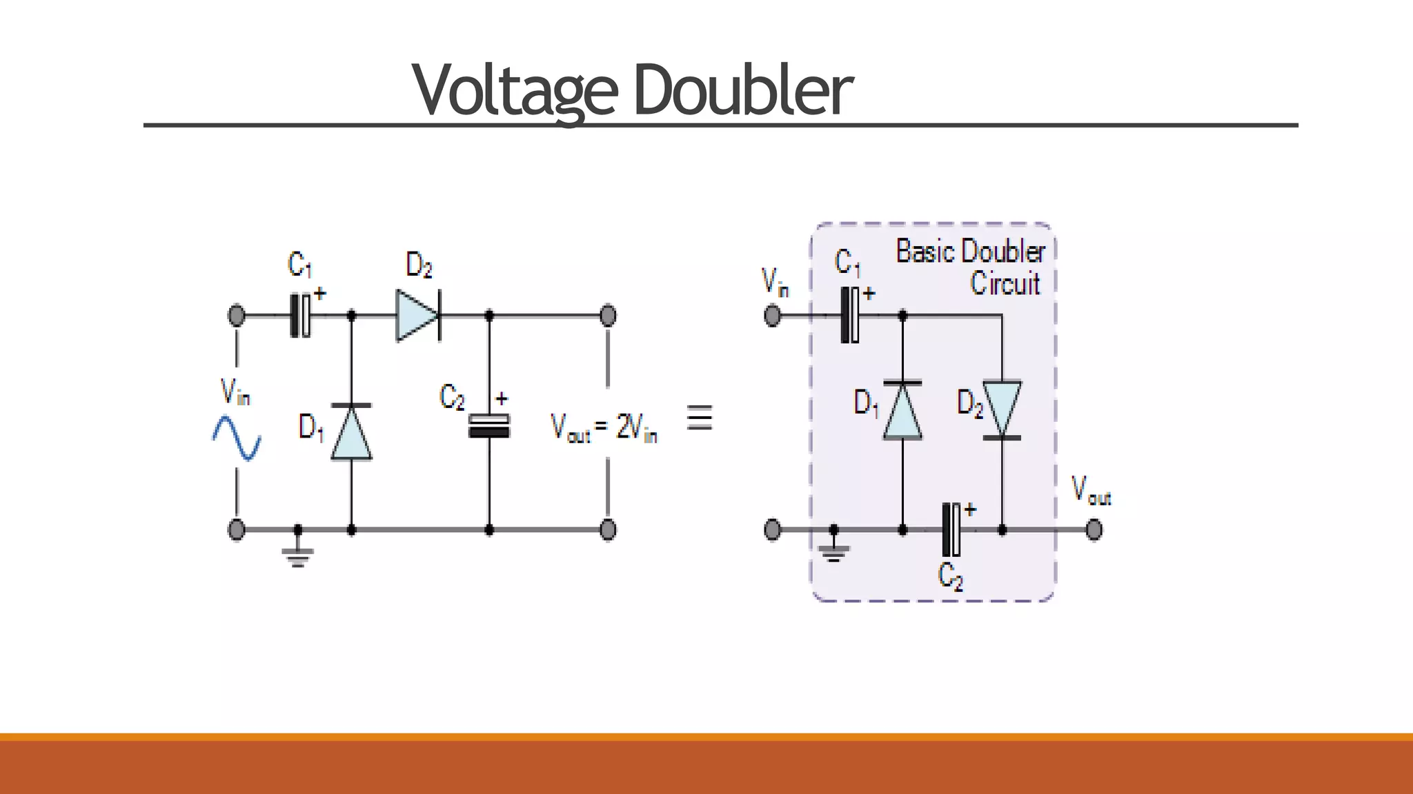
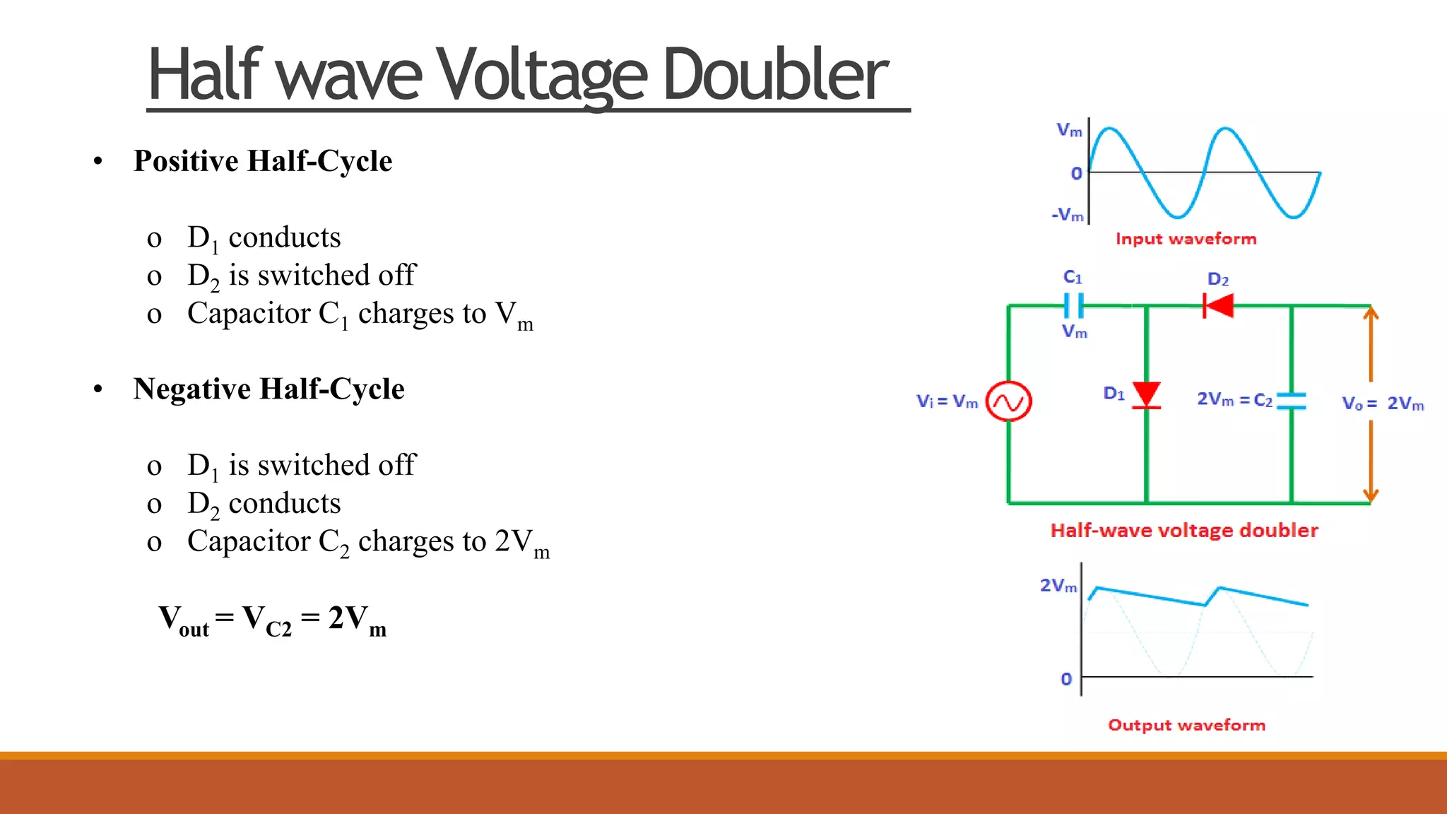
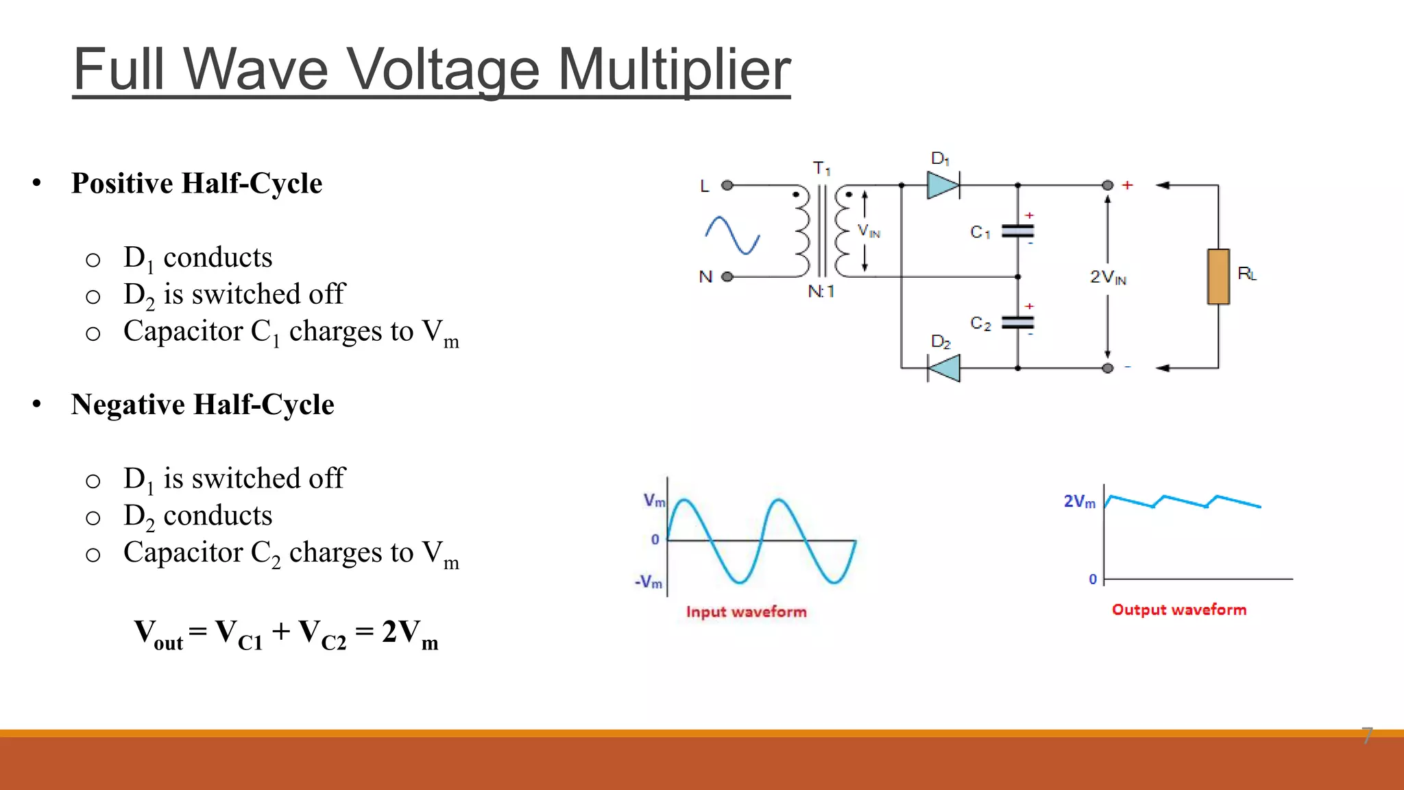
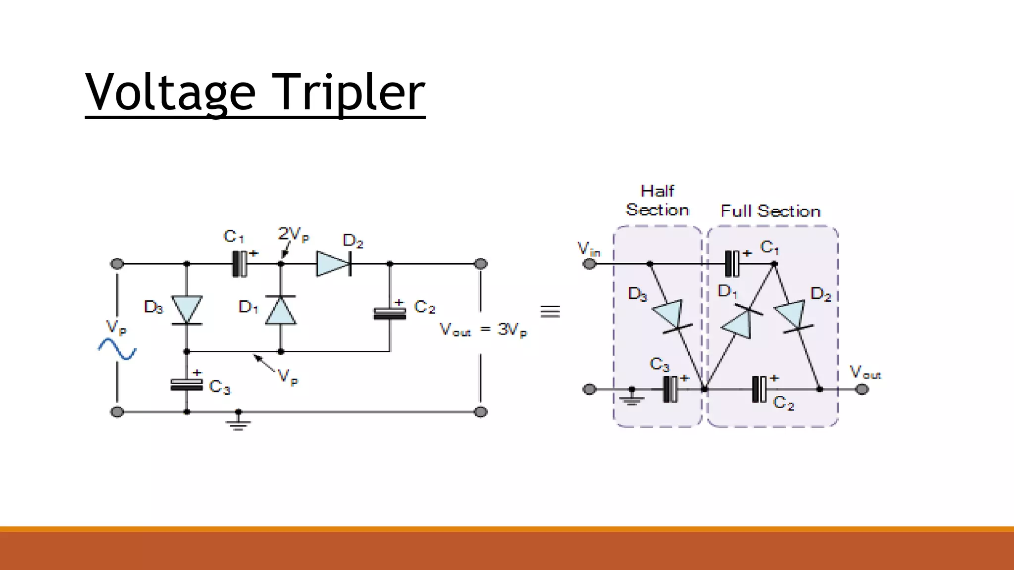

A voltage multiplier is an electrical circuit that uses capacitors and diodes to convert AC power to higher DC voltage. There are different types depending on the output voltage, including half-wave and full-wave doublers, and triplers and quadruplers that output higher multiples of the input voltage. Voltage multipliers function by charging capacitors on alternating half-cycles to add voltage levels. They are used to provide high voltages in applications like CRTs, lasers, x-rays, and particle accelerators. While lower current and delays are disadvantages, voltage multipliers provide high voltage at low cost as an alternative to transformers.
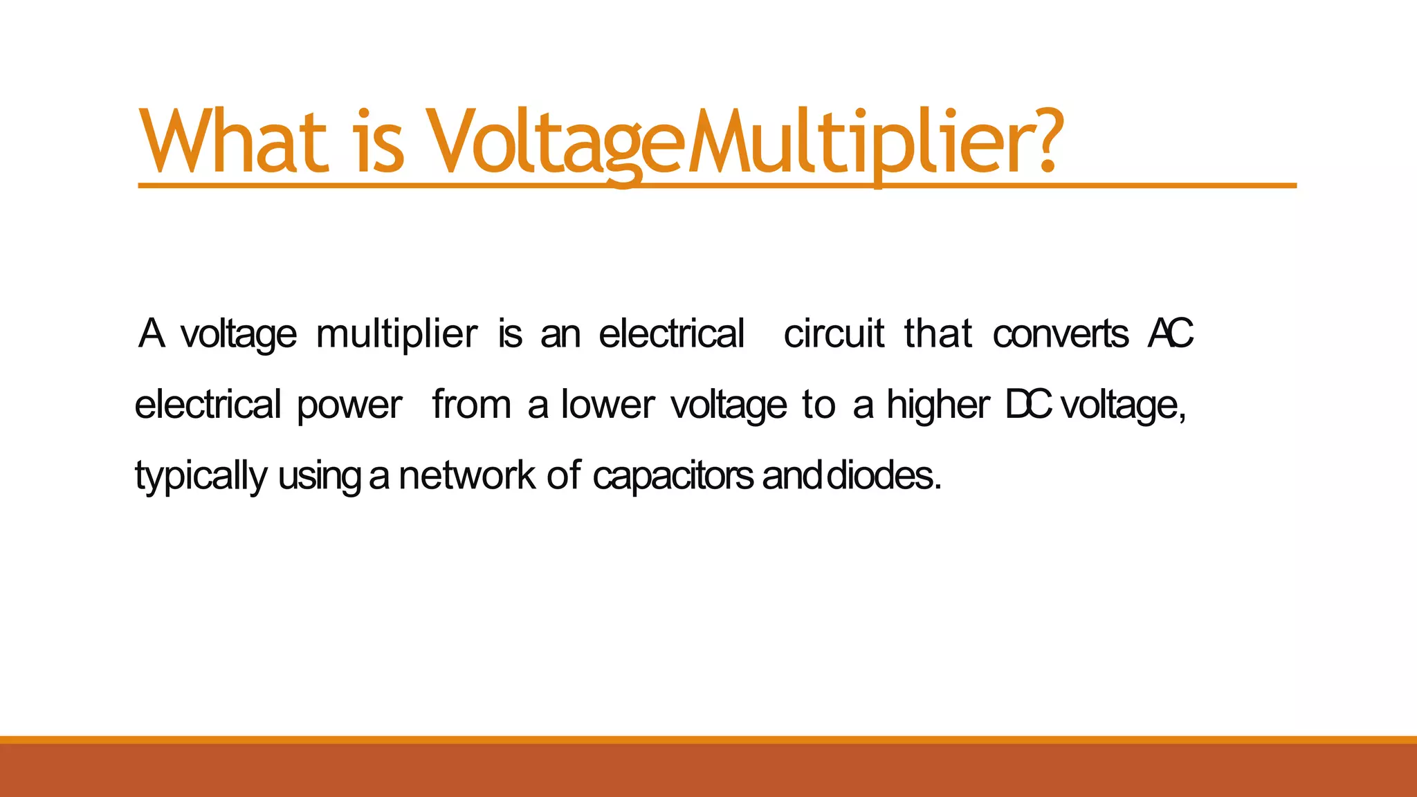
Introduction to voltage multipliers that convert lower AC voltage to higher DC voltage.
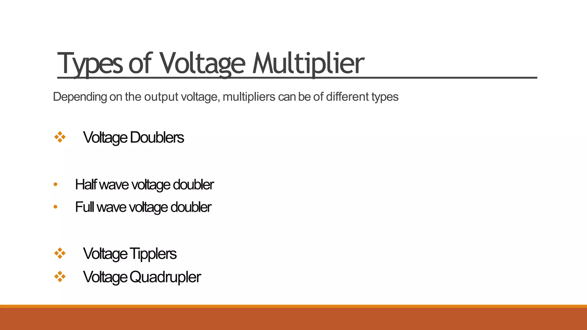
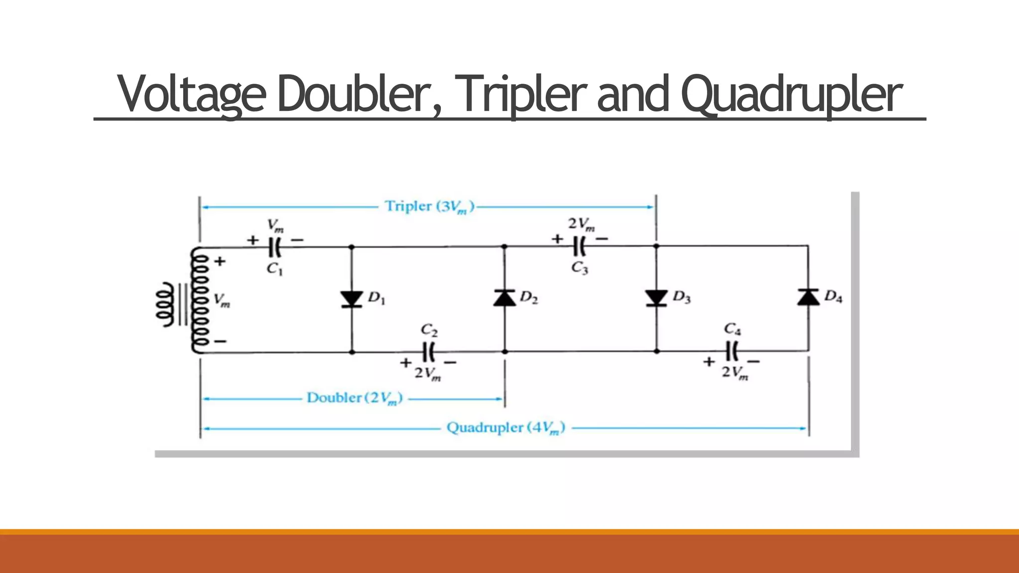
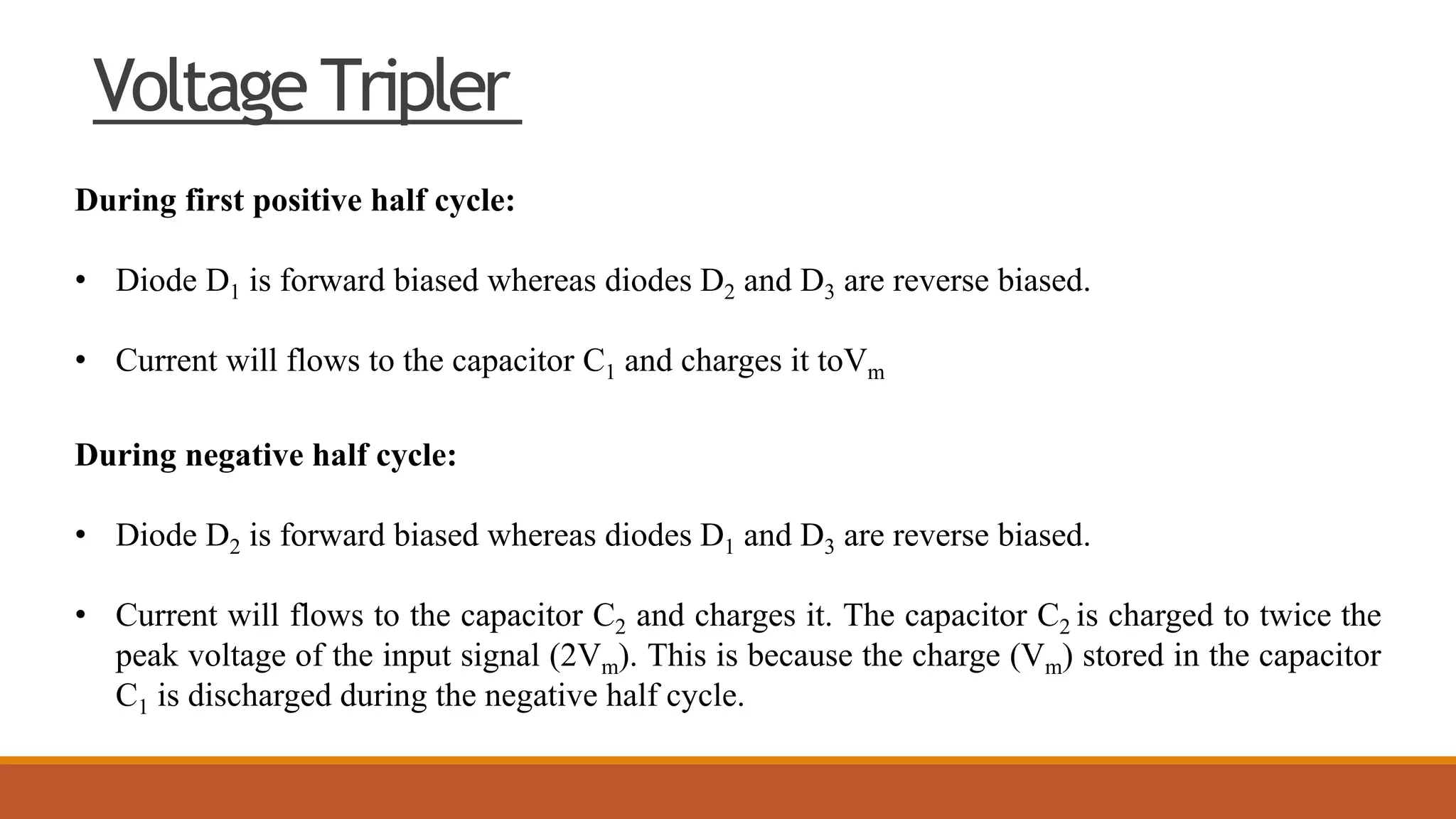
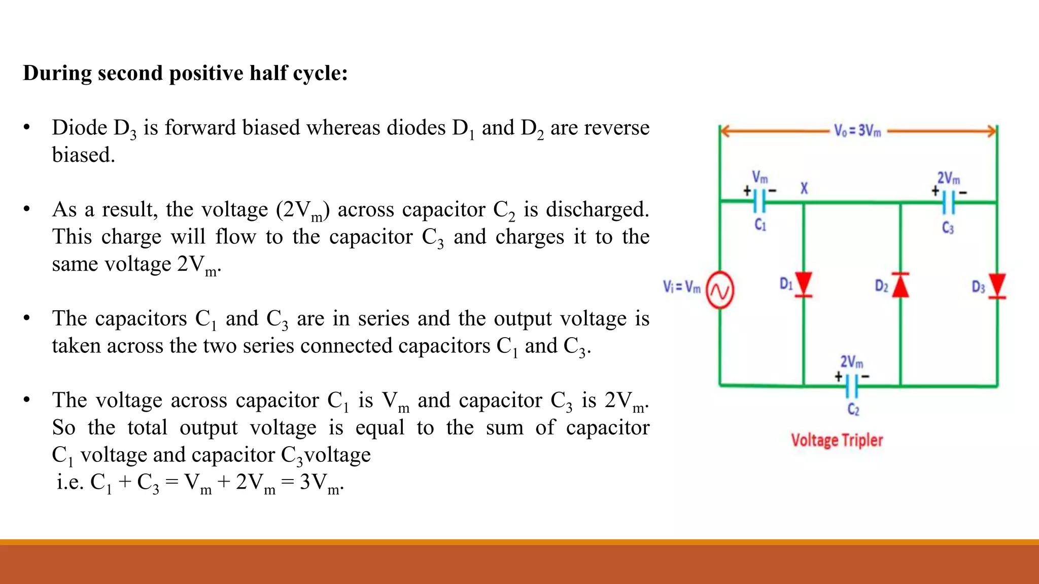
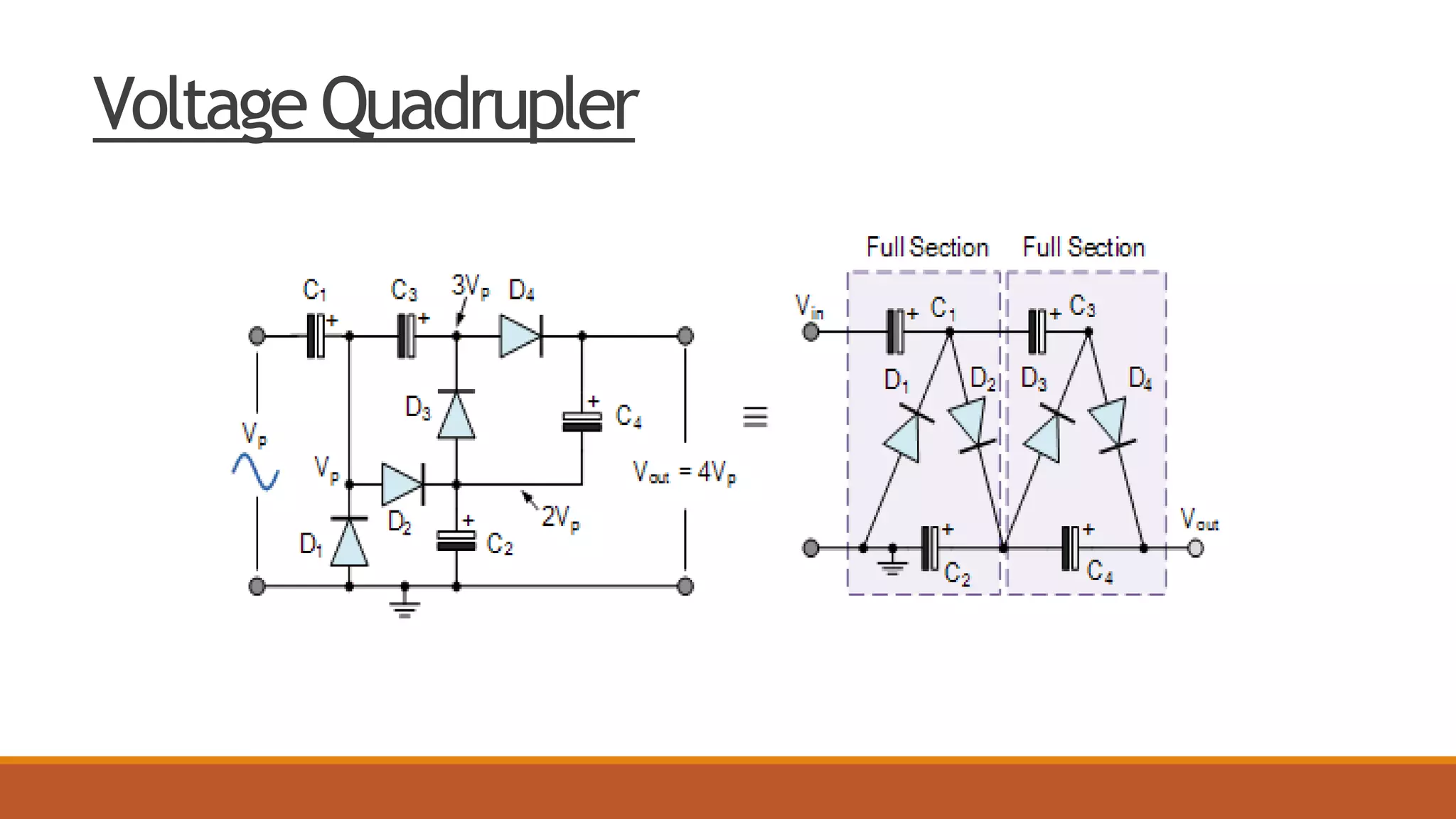
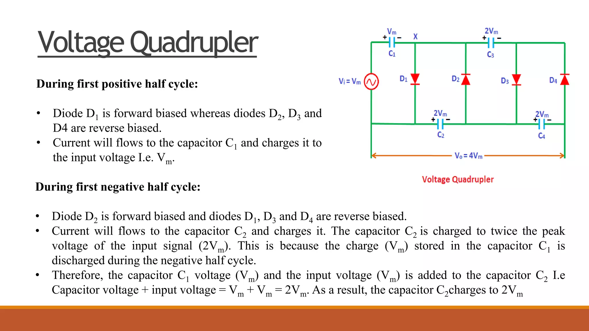
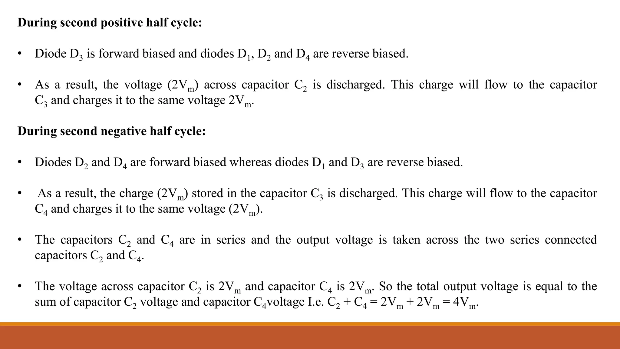
Different types of voltage multipliers explained: doublers, triplers, and quadruplers. Mechanisms and output voltages for each type.
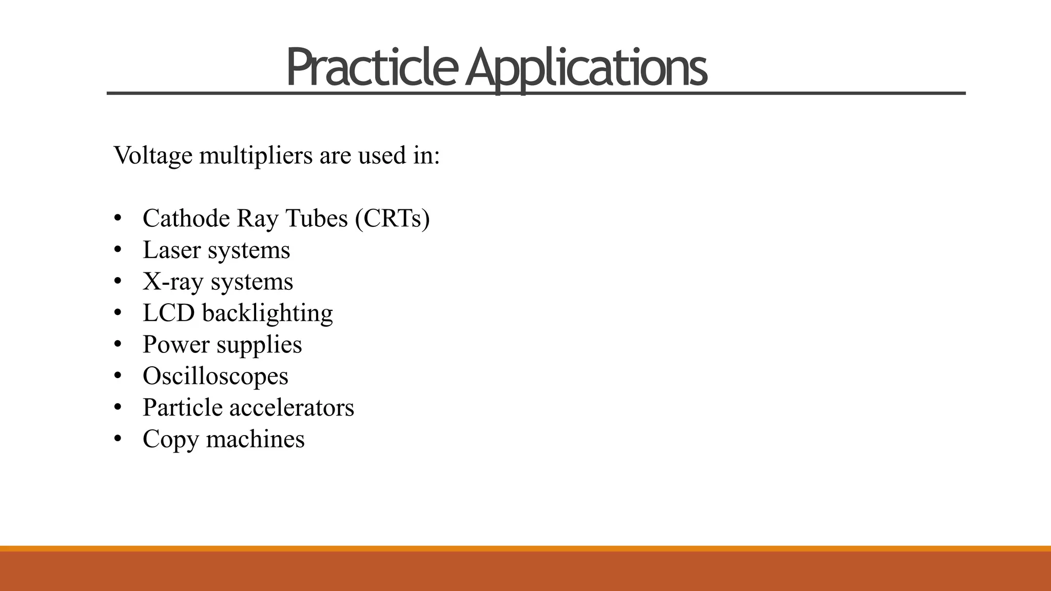
Practical applications of voltage multipliers across various fields like CRTs, lasers, and power supplies.
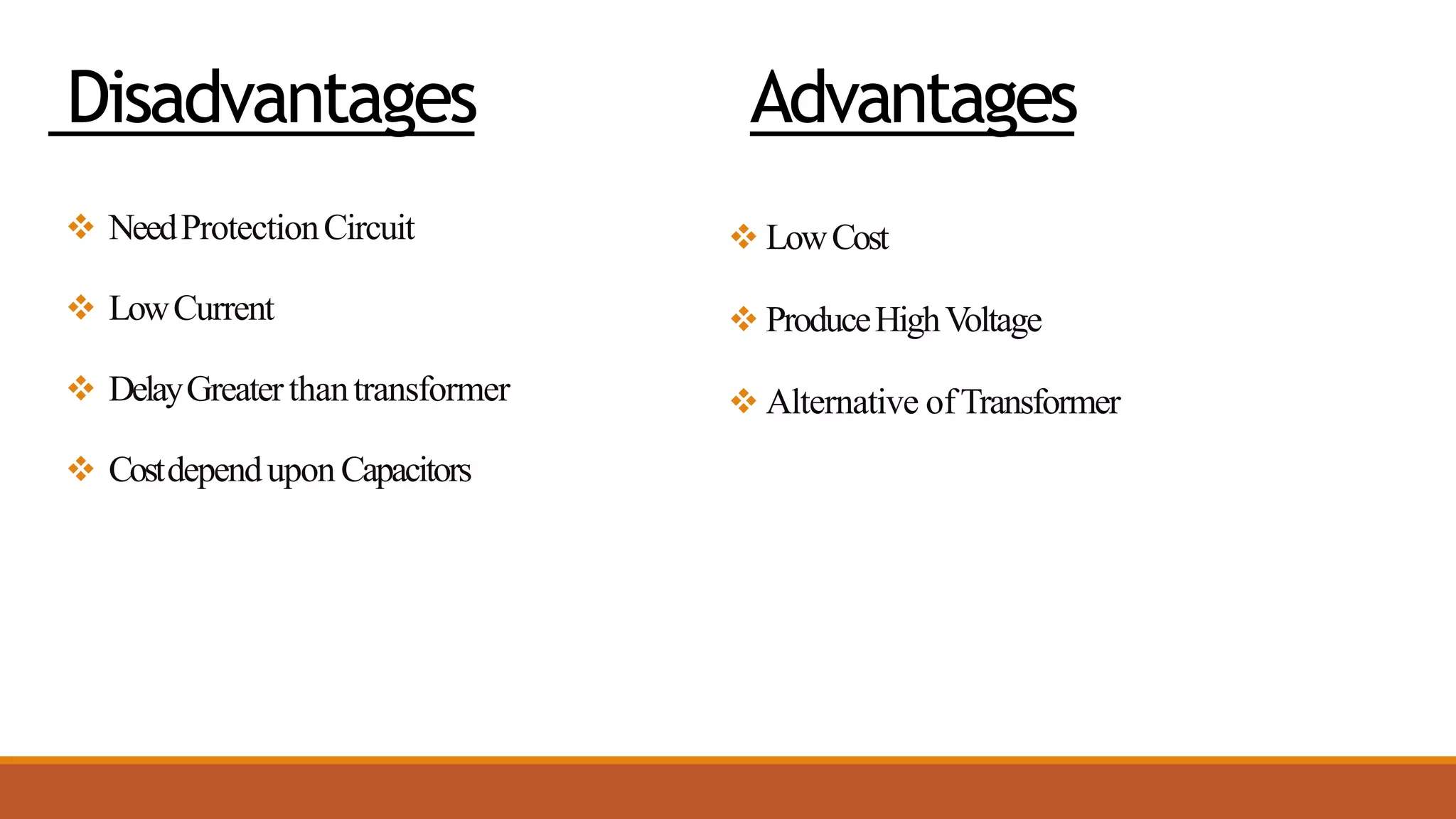
Advantages: high voltage and cost-effective; Disadvantages: require protection circuits and have low current.


![REGULATED_POWER_SUPPLY-1[1].pptx](https://cdn.slidesharecdn.com/ss_thumbnails/regulatedpowersupply-11-220731133419-9084246e-thumbnail.jpg?width=640&height=640&fit=bounds)


