Downloaded 456 times


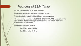
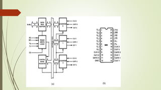
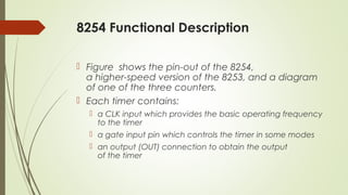
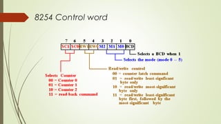

The 8254 timer has 3 independent 16-bit counters that can be programmed to operate in 6 different modes, including generating interrupts, oneshots, square waves, and strobes. Each counter is controlled by a programmable word and clock input, and can count in binary or BCD. The 8254 provides improved frequency operation over the 8253, up to 10 MHz.