Downloaded 655 times

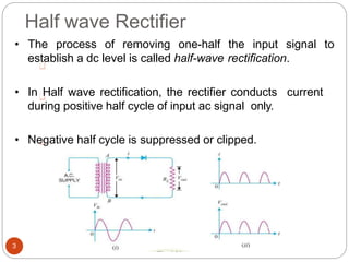


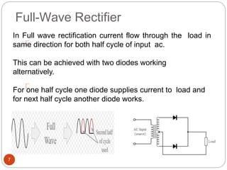
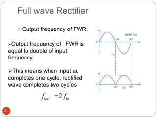


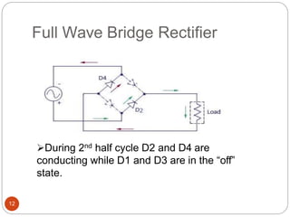


Rectifiers convert alternating current (AC) to direct current (DC). There are two main types: half-wave and full-wave rectifiers. Half-wave rectifiers only conduct current during one half of the AC cycle, resulting in lower power output. Full-wave rectifiers conduct current during both halves of the cycle, doubling the output frequency and improving power output. Common full-wave rectifier circuits include the center-tap and bridge rectifier configurations using different diode arrangements.


