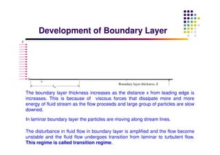
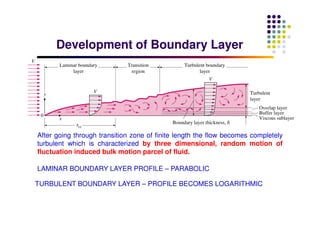
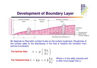
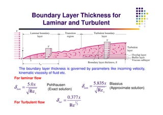
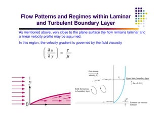
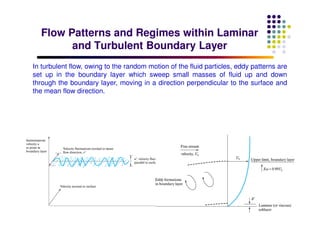
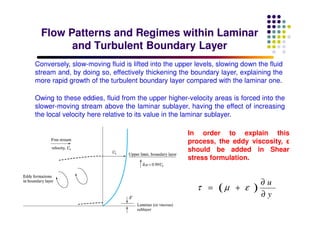
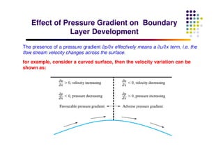
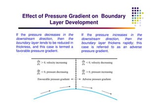
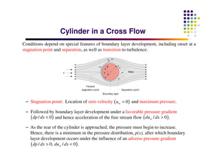
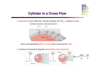
Risk Assessment For Installation of Drainage Pipes.pdf
Boundary layer theory
1. Dr. Rajesh Patel
Mechanical Engineering Department
School of Technology
Pandit Deendayal Petroleum University
Introduction of Boundary Layer DevelopmentIntroduction of Boundary Layer Development
2. IntroductionIntroduction
The drag on a body passing through a fluid may be considered to be made up of
two components: Form drag and Skin friction drag.
Form drag: which is dependent on the pressure forces acting on the body; and
the skin friction drag , which depends on the shearing forces acting between
the body and the fluid.
3. Shear Force and Pressure ForceShear Force and Pressure Force
Shear forces:
viscous drag, frictional drag, or skin friction
caused by shear between the fluid and the
solid surface
function of ___________and ______of
object
surface area length
flow separation
UU
UU
Major losses in pipes
Flow expansion
losses
Projected area
Pressure forces
pressure drag or form drag
caused by _____________from the body
function of area normal to the flow
4. Description of Boundary LayerDescription of Boundary Layer
τw: wall shear stresses
U δ
In the immediate vicinity of the boundary surface, the velocity of the fluid
increases gradually from zero at boundary surface to the velocity of the
mainstream. This region is known as BOUNDARY LAYER.
Large velocity gradient leading to appreciable shear stress:
0y
u
y
τ µ
=
∂
=
∂
The nominal thickness of BOUNDARY LAYER is defined as the distance from
the boundary where the velocity of fluid is 99 % of free stream velocity
5. Description of Boundary LayerDescription of Boundary Layer
τw: wall shear stresses
U δ
shear stress: u
y
τ µ
∂
=
∂
Shear stress acting at the plate surface
sets up a shear force which opposes
the fluid motion, and fluid close to the
wall is decelerated.
Theoretical understanding on Boundary layer development is very important to
determine the velocity gradient and hence shear forces on the surface.
Consists of two layers:
CLOSE TO BOUNDARY : large velocity gradient, appreciable viscous forces.
OUTSIDE BOUNDARY LAYER: viscous forces are negligible, flow may be
treated as non-viscous or inviscid.
6. Development of Boundary LayerDevelopment of Boundary Layer
In laminar boundary layer the particles are moving along stream lines.
The boundary layer thickness increases as the distance x from leading edge is
increases. This is because of viscous forces that dissipate more and more
energy of fluid stream as the flow proceeds and large group of particles are slow
downed.
The disturbance in fluid flow in boundary layer is amplified and the flow become
unstable and the fluid flow undergoes transition from laminar to turbulent flow.
This regime is called transition regime.
7. Development of Boundary LayerDevelopment of Boundary Layer
After going through transition zone of finite length the flow becomes completely
turbulent which is characterized by three dimensional, random motion of
fluctuation induced bulk motion parcel of fluid.
LAMINAR BOUNDARY LAYER PROFILE – PARABOLIC
TURBULENT BOUNDARY LAYER – PROFILE BECOMES LOGARITHMIC
8. Development of Boundary LayerDevelopment of Boundary Layer
BL depends on Reynold’s number & also on the surface roughness. Roughness of
the surface adds to the disturbance in the flow & hastens the transition from
laminar to turbulent.
For laminar flow
u
y
τ µ
∂
=
∂
For Turbulent flow ( )
u
y
τ µ ε
∂
= +
∂
Where ε is the eddy viscosity and
is often much larger than µ
.
9. Boundary Layer Thickness for
Laminar and Turbulent
Boundary Layer Thickness for
Laminar and Turbulent
For laminar flow
For Turbulent flow
The boundary layer thickness is governed by parameters like incoming velocity,
kinematic viscosity of fluid etc.
5.0
Re
lam
x
x
δ =
Pohlhausen
(Exact solution)
5.835
Re
lam
x
x
δ =
Blassius
(Approximate solution)
1
5
0.377
Re
tur
x
δ =
10. Flow Patterns and Regimes within Laminar
and Turbulent Boundary Layer
Flow Patterns and Regimes within Laminar
and Turbulent Boundary Layer
As mentioned above, very close to the plane surface the flow remains laminar and
a linear velocity profile may be assumed.
In this region, the velocity gradient is governed by the fluid viscosity
u
y
τ
µ
∂
=
∂
11. Flow Patterns and Regimes within Laminar
and Turbulent Boundary Layer
Flow Patterns and Regimes within Laminar
and Turbulent Boundary Layer
In turbulent flow, owing to the random motion of the fluid particles, eddy patterns are
set up in the boundary layer which sweep small masses of fluid up and down
through the boundary layer, moving in a direction perpendicular to the surface and
the mean flow direction.
12. Flow Patterns and Regimes within Laminar
and Turbulent Boundary Layer
Flow Patterns and Regimes within Laminar
and Turbulent Boundary Layer
Owing to these eddies, fluid from the upper higher-velocity areas is forced into the
slower-moving stream above the laminar sublayer, having the effect of increasing
the local velocity here relative to its value in the laminar sublayer.
Conversely, slow-moving fluid is lifted into the upper levels, slowing down the fluid
stream and, by doing so, effectively thickening the boundary layer, explaining the
more rapid growth of the turbulent boundary layer compared with the laminar one.
In order to explain this
process, the eddy viscosity, ε
should be added in Shear
stress formulation.
( )
u
y
τ µ ε
∂
= +
∂
13. Effect of Pressure Gradient on Boundary
Layer Development
Effect of Pressure Gradient on Boundary
Layer Development
The presence of a pressure gradient ∂p/∂x effectively means a ∂u/∂x term, i.e. the
flow stream velocity changes across the surface.
for example, consider a curved surface, then the velocity variation can be
shown as:
14. Effect of Pressure Gradient on Boundary
Layer Development
Effect of Pressure Gradient on Boundary
Layer Development
If the pressure decreases in the
downstream direction, then the
boundary layer tends to be reduced in
thickness, and this case is termed a
favorable pressure gradient.
If the pressure increases in the
downstream direction, then the
boundary layer thickens rapidly; this
case is referred to as an adverse
pressure gradient.
15. Cylinder in a Cross FlowCylinder in a Cross Flow
Conditions depend on special features of boundary layer development, including onset at a
stagnation point and separation, as well as transition to turbulence.
– Stagnation point: Location of zero velocity and maximum pressure.( )0u∞ =
– Followed by boundary layer development under a favorable pressure gradient
and hence acceleration of the free stream flow .( )/ 0<dp dx ( )/ 0∞ >du dx
– As the rear of the cylinder is approached, the pressure must begin to increase.
Hence, there is a minimum in the pressure distribution, p(x), after which boundary
layer development occurs under the influence of an adverse pressure gradient
( )/ 0, / 0 .∞> <dp dx du dx
16. – Separation occurs when the velocity gradient reduces to zero.0/ =ydu dy
and is accompanied by flow reversal and a downstream wake.
– Location of separation depends on boundary layer transition.
ReD
VD VDρ
µ ν
≡ =
Cylinder in a Cross FlowCylinder in a Cross Flow