Downloaded 913 times


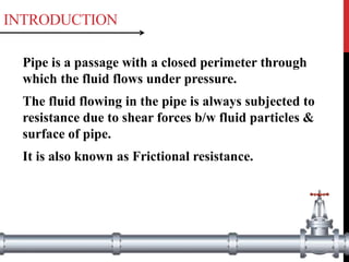
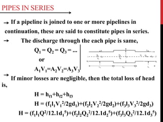
![ii)Loss due to sudden contraction:-
It is due to sudden contraction
of pipe.
It is denoted by hc.
V
hc = [(1/Cc)-1]2 x v2/(2g)
iii)Loss at the exit:-
It is head loss at the exit of
the pipe.
It is denoted by hex.
V
hex = v2/(2g)](https://image.slidesharecdn.com/flowthroughpipes-190224091237/85/Flow-through-pipes-7-320.jpg)
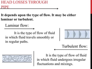
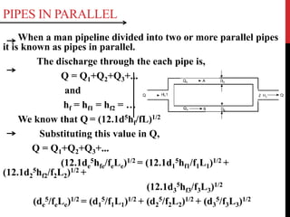
![iv)Loss due to pipe fittings:-
It is due to pipe fittings like
elbows, valves etc.
It is denoted by hb.
hb= K[v2/(2g)]
v)Loss at entrance :-
It is head loss at the entrance of
the pipe.
It is denoted by hen.
V
hen = 0.5[v2/(2g)]](https://image.slidesharecdn.com/flowthroughpipes-190224091237/85/Flow-through-pipes-8-320.jpg)
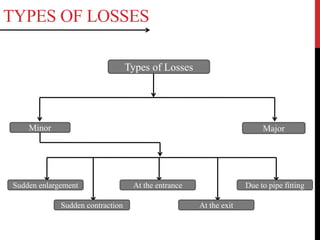
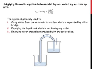
![Hydraulic Grade Line
It is the line joining all the liquid
levels in piezometers.
It is the sum of pressure head &
datum head [(P/γ)+z].
Slope of HGL is called as
hydraulic gradient.
Total Energy Line
It is graphical representation of total
head at various points along pipe.
It is the sum of pressure head, velocity
head & datum head.
[(P/γ)+(v2/2g)+z].
If datum is 0 then energy grade line is
TEL.](https://image.slidesharecdn.com/flowthroughpipes-190224091237/85/Flow-through-pipes-9-320.jpg)
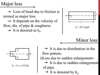
![SYPHON SYPHON IS LONG BENT PIPE WHICH IS USED TO CONVEY
LIQUID FROM A RESERVOIR AT A HIGHER ELEVATION WHEN
THE TWO ARE SEPARATED BY A HIGH LEVEL GROUND OR HILL.
THE HIGHEST POINT OF THE SYPHON I.E. A POINT ABOVE FREE
SURFACE OF RESERVOIR IS KNOWN AS SUMMIT.
THE PORTION OF SYPHON WHICH IS CONNECTED WITH SOURCE
RESERVOIR IS CALLED INLET LEG AND THE OUTPUT RESERVOIR
IS CALLED OUTLET LEG.
THE FLOW THROUGH THE SYPHON IS ONLY POSSIBLE IF THE
PRESSURE AT THE SUMMIT IS BELOW ATMOSPHERIC PRESSURE.
HOWEVER PRESSURE AT SUMMIT SHOULD NOT FALL BELOW THE
SATURATION PRESSURE OF THE LIQUID OTHERWISE VAPOR
WILL START FORMING, CAUSING THE CAVITATION IN SYPHON
AND FLOW OF WATER WILL BE OBSTRUCTED.
APPLYING BERNOULLI’S THEOREM BETWEEN INLET LEG AND
SUMMIT WE COME UP WITH,
𝑙 𝑖 =
𝑔 𝑥 𝐷 [ℎ𝑎𝑡𝑚 − ℎ𝑠 − ℎ𝑖 −
𝑣2
2𝑔
]
2𝑓𝑣2](https://image.slidesharecdn.com/flowthroughpipes-190224091237/85/Flow-through-pipes-12-320.jpg)

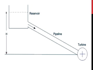
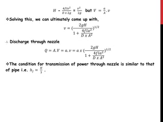
![POWER TRANSMISSION THROUGH
PIPE
Power can be transmitted by liquid which is flowing through pipes.
Power transmission through pipes is commonly used to convey water from
a high level reservoir to turbine house and in operation of hydraulic
equipments such as hydraulic press, crane jack , etc.
The power transmitted depends upon the weight of liquid flowing through
pipe and total head available at end of pipe.
Thus, Power transmitted through pipe
𝑃 = 𝑤𝑒𝑖𝑔ℎ𝑡 𝑜𝑓 𝑤𝑎𝑡𝑒𝑟 𝑓𝑙𝑜𝑤 𝑡ℎ𝑟𝑜𝑢𝑔ℎ 𝑝𝑖𝑝𝑒 𝑥 𝐻𝑒𝑎𝑑 𝑎𝑣𝑎𝑖𝑙𝑎𝑏𝑙𝑒 𝑎𝑡 𝑜𝑢𝑡𝑙𝑒𝑡 𝑜𝑓 𝑝𝑖𝑝𝑒
= 𝑊 𝑥 [𝐻 − ℎ𝑓]
= 𝑚𝑔 𝑥 [𝐻 − ℎ𝑓]
= 𝜌. 𝐴. 𝑉. 𝑔 𝑥 [𝐻 − ℎ𝑓]
∴ P = 𝜌. 𝑔.
𝛱𝐷2
4
. 𝑉 𝑥 [𝐻 −
4𝑓𝑙𝑣2
𝐷 𝑥 2𝑔
] W](https://image.slidesharecdn.com/flowthroughpipes-190224091237/85/Flow-through-pipes-15-320.jpg)


This document provides an overview of fluid mechanics concepts related to flow through pipes. It discusses different types of head losses that can occur through pipes including major losses due to friction and minor losses due to fittings. It also covers topics such as hydraulic grade line, pipes in series and parallel, syphons, power transmission through pipes, flow through nozzles, and water hammer effects in pipes.


