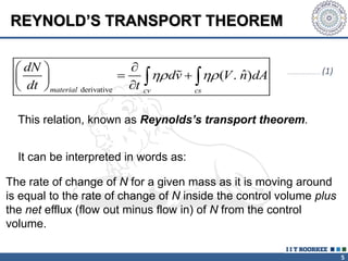
1. Reynolds transport theorem relates the rate of change of a property within a control volume to the rate of change of the property convected with a moving fluid plus the net flux of the property entering and leaving the control volume.
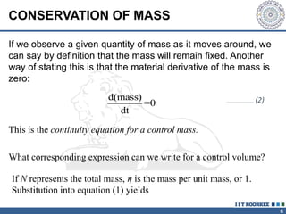
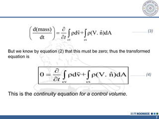
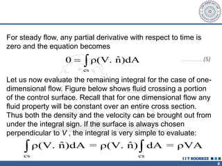
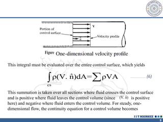
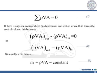
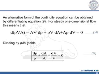
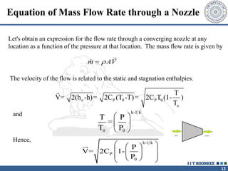
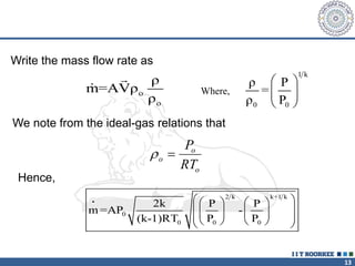
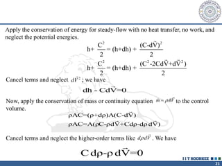
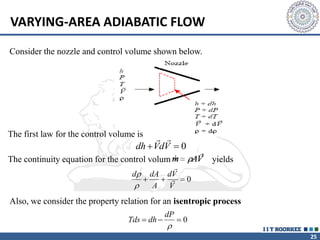
2. The continuity equation states that for a fixed mass of fluid, the net mass flow entering and leaving a control volume is zero. For steady one-dimensional flow, the mass flow rate is constant.
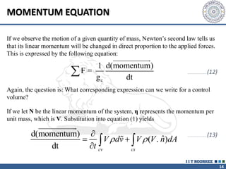
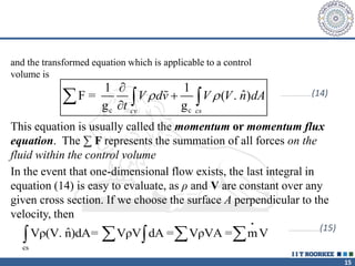
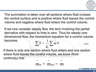
3. The momentum equation equates the net external forces on a control volume to the rate of change of momentum entering and leaving the control volume. For steady one-dimensional flow, the momentum flow rate is constant.