Downloaded 425 times

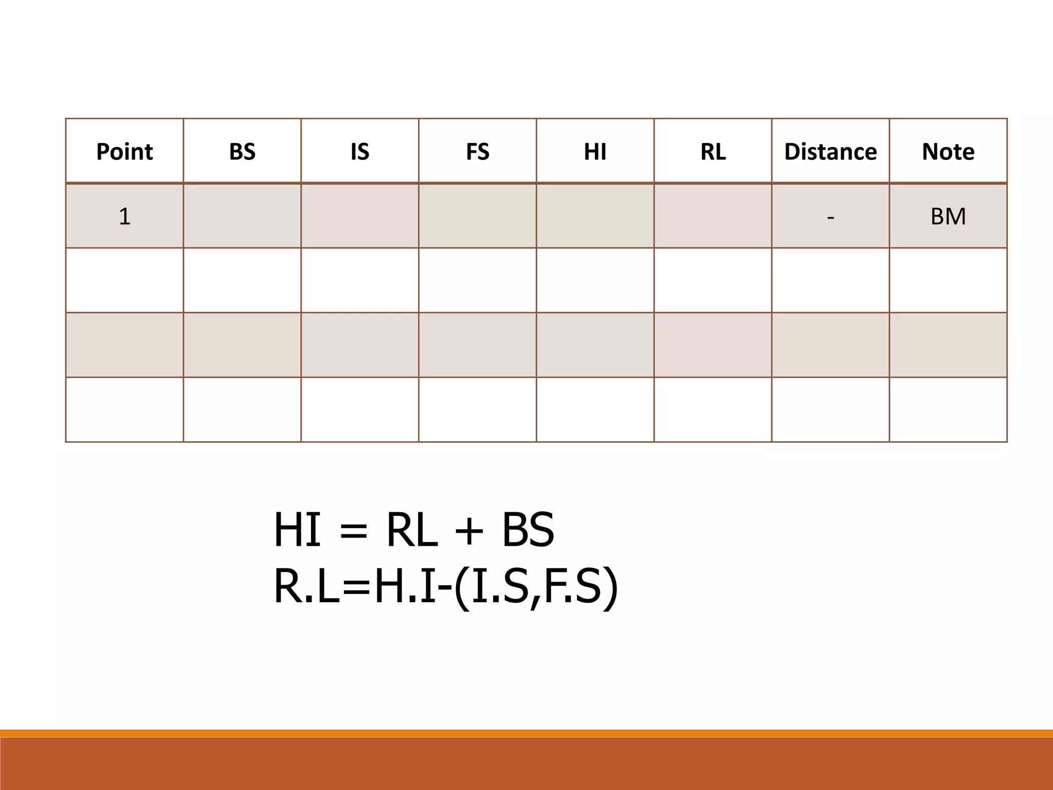


![Point BS IS FS HI RL Distance Note
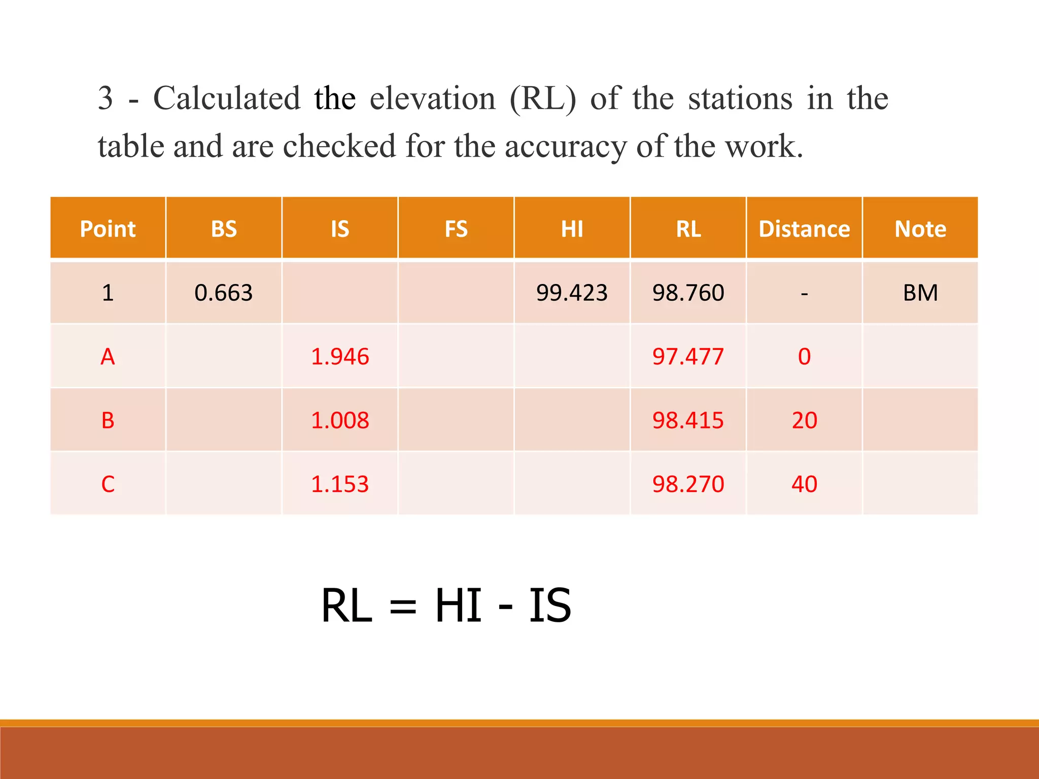
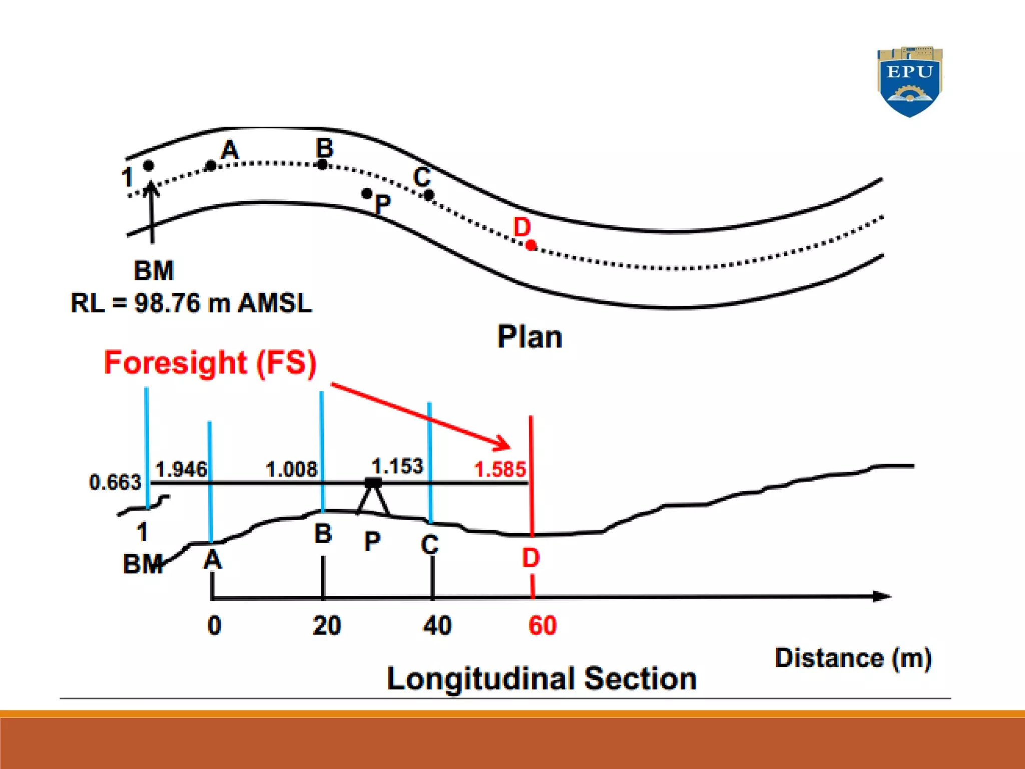
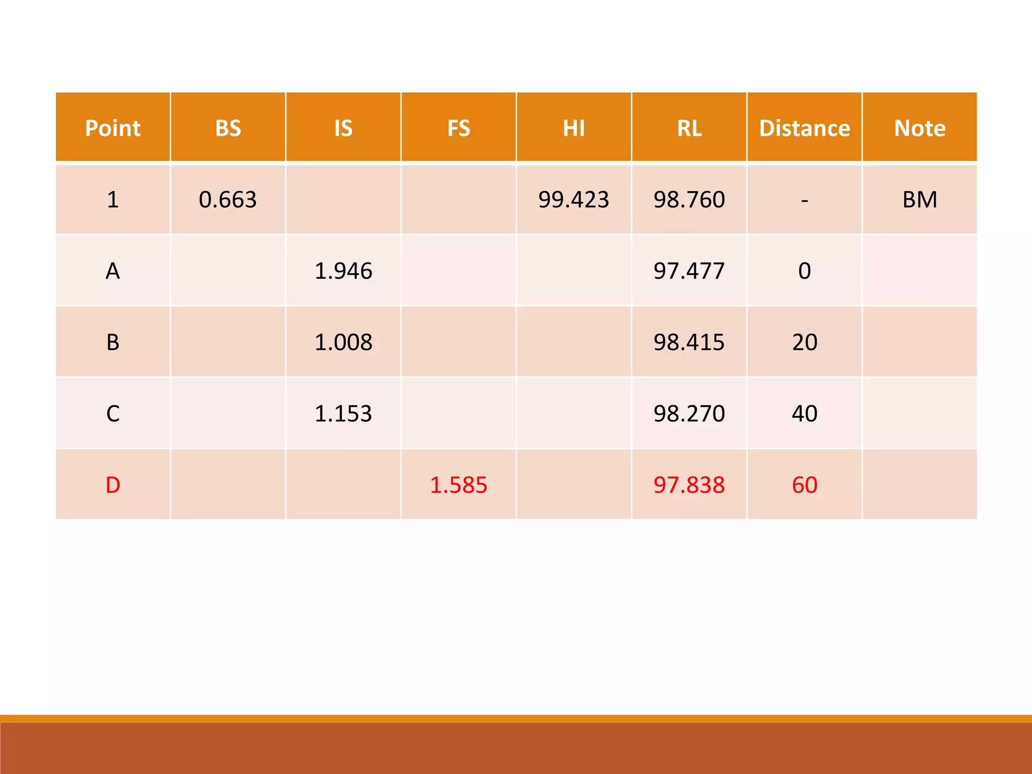
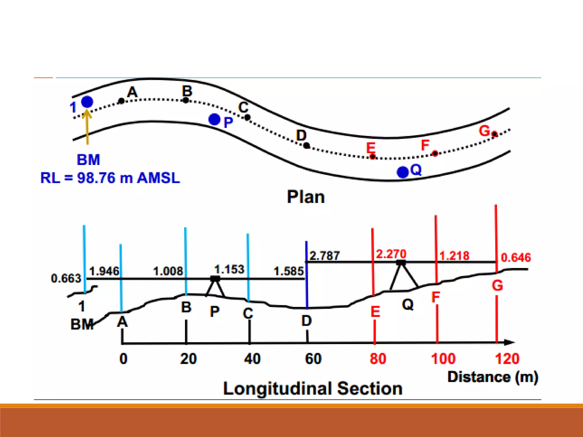
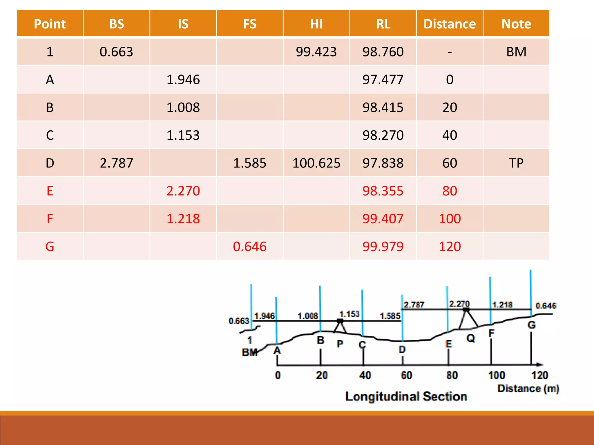
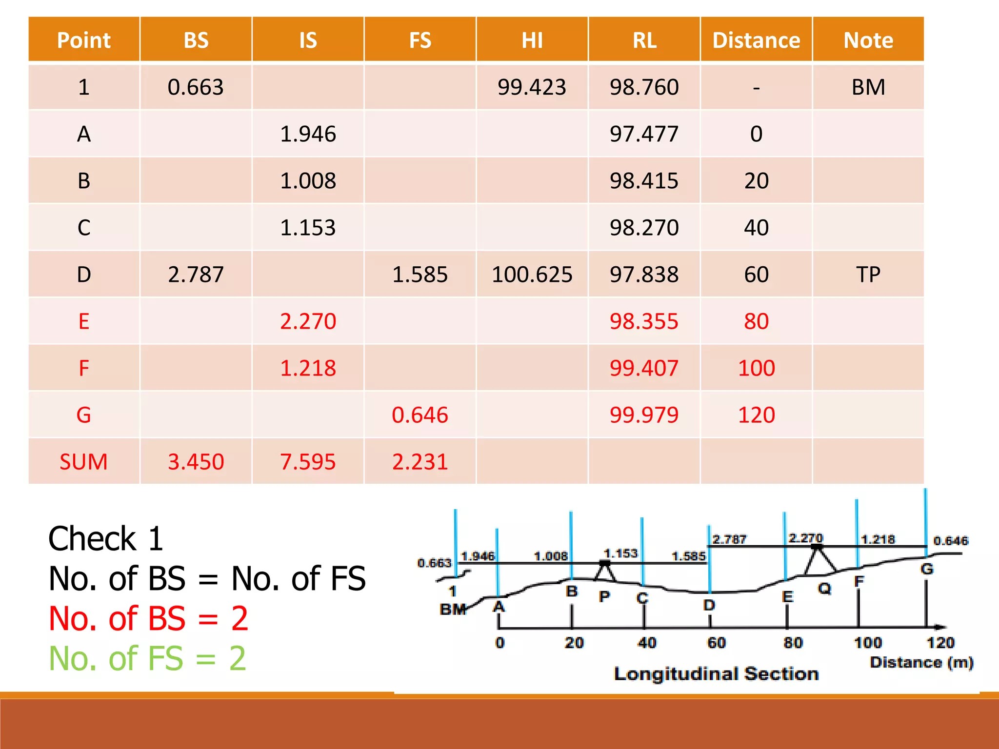
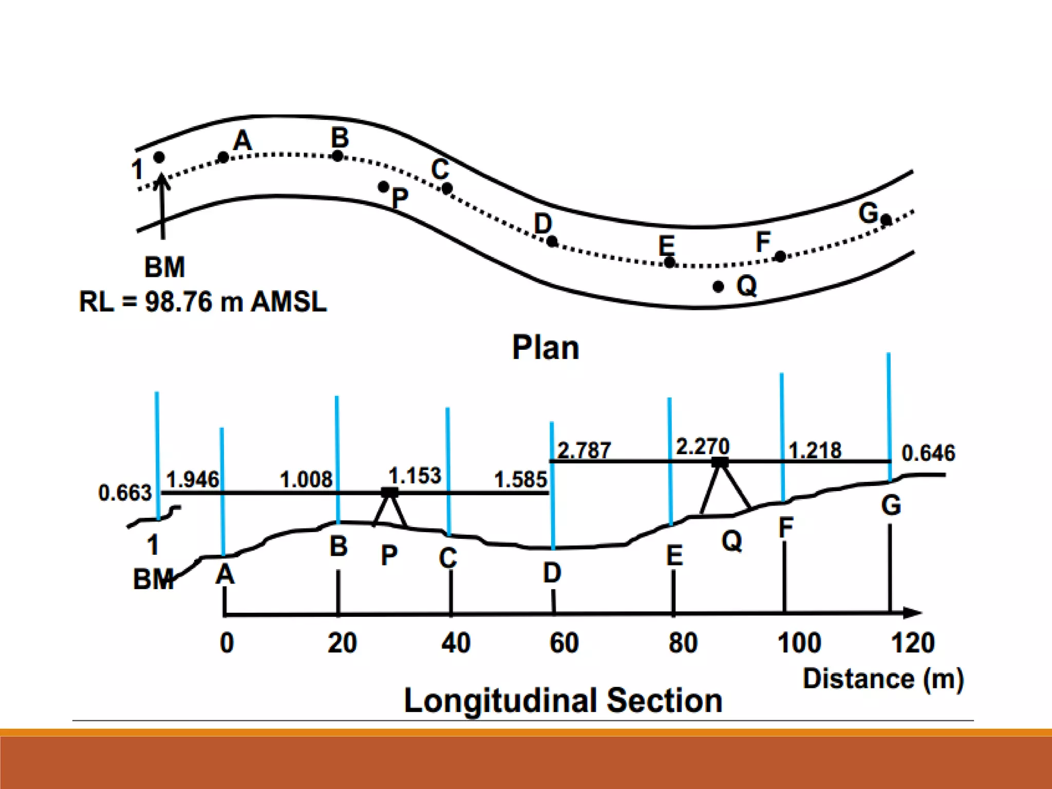
1 0.663 99.423 98.760 - BM
A 1.946 97.477 0
B 1.008 98.415 20
C 1.153 98.270 40
D 2.787 1.585 100.625 97.838 60 TP
E 2.270 98.355 80
F 1.218 99.407 100
G 0.646 99.979 120
SUM 3.450 7.595 2.231
Check 3
ΣRL – RL first point = [Σ (No. of IS & FS x HI)]- Σ IS- Σ FS
ΣRL – RL first point = 689.741
[Σ (No. of IS & FSx HI)]- Σ IS- Σ FS
=[99.423x4 + 100.625x3] – 7.595 – 2.231 = 689.741](https://image.slidesharecdn.com/profileslongitudinalsectioncrosssections-220910202856-42ebe669/75/Profiles-longitudinal-section-cross-sections-25-2048.jpg)
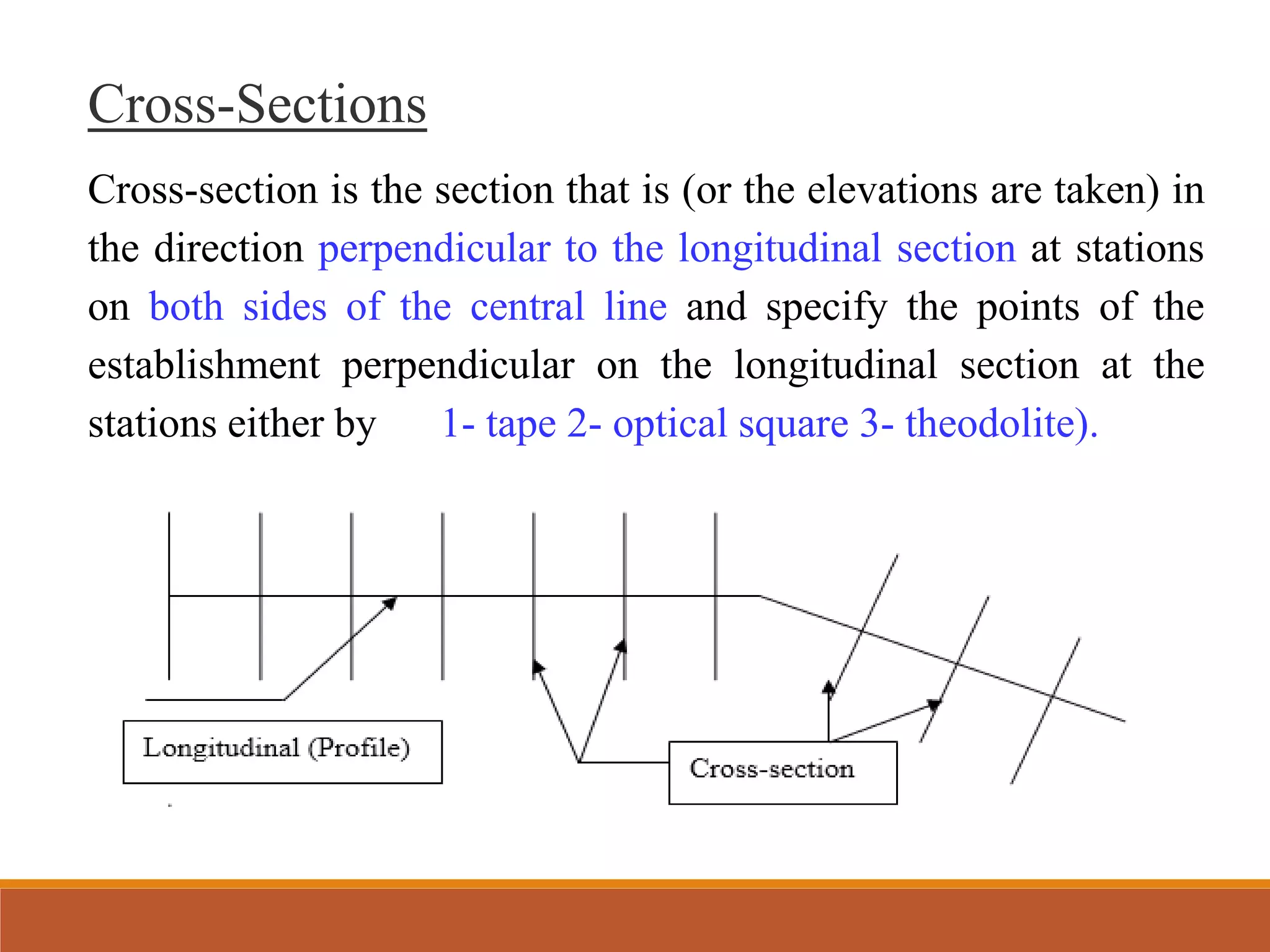
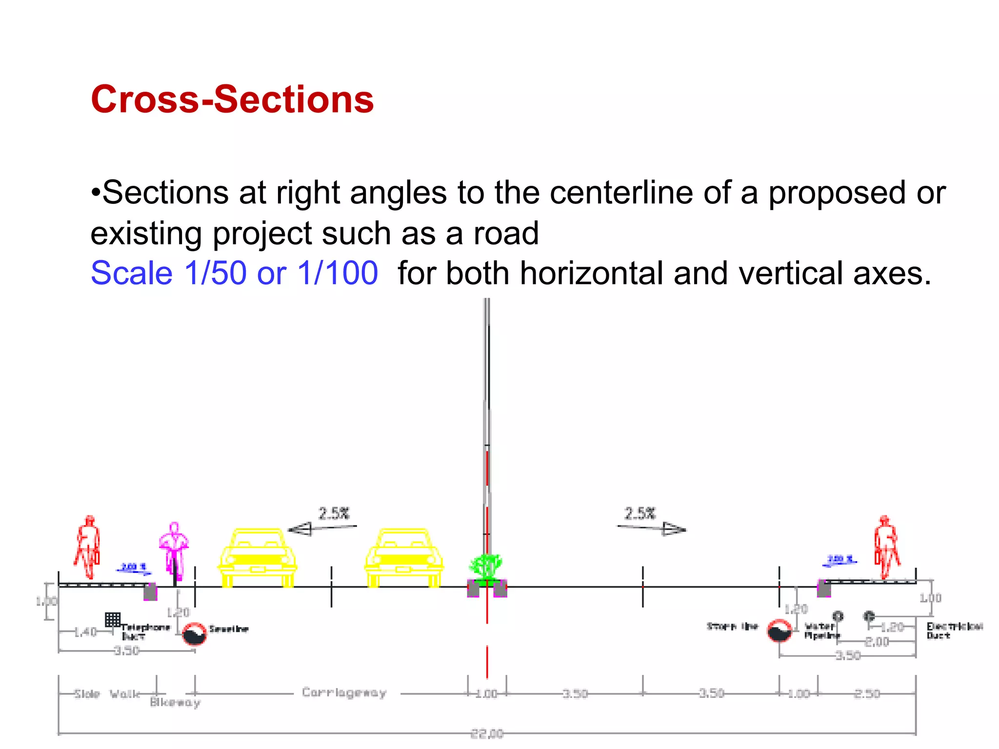
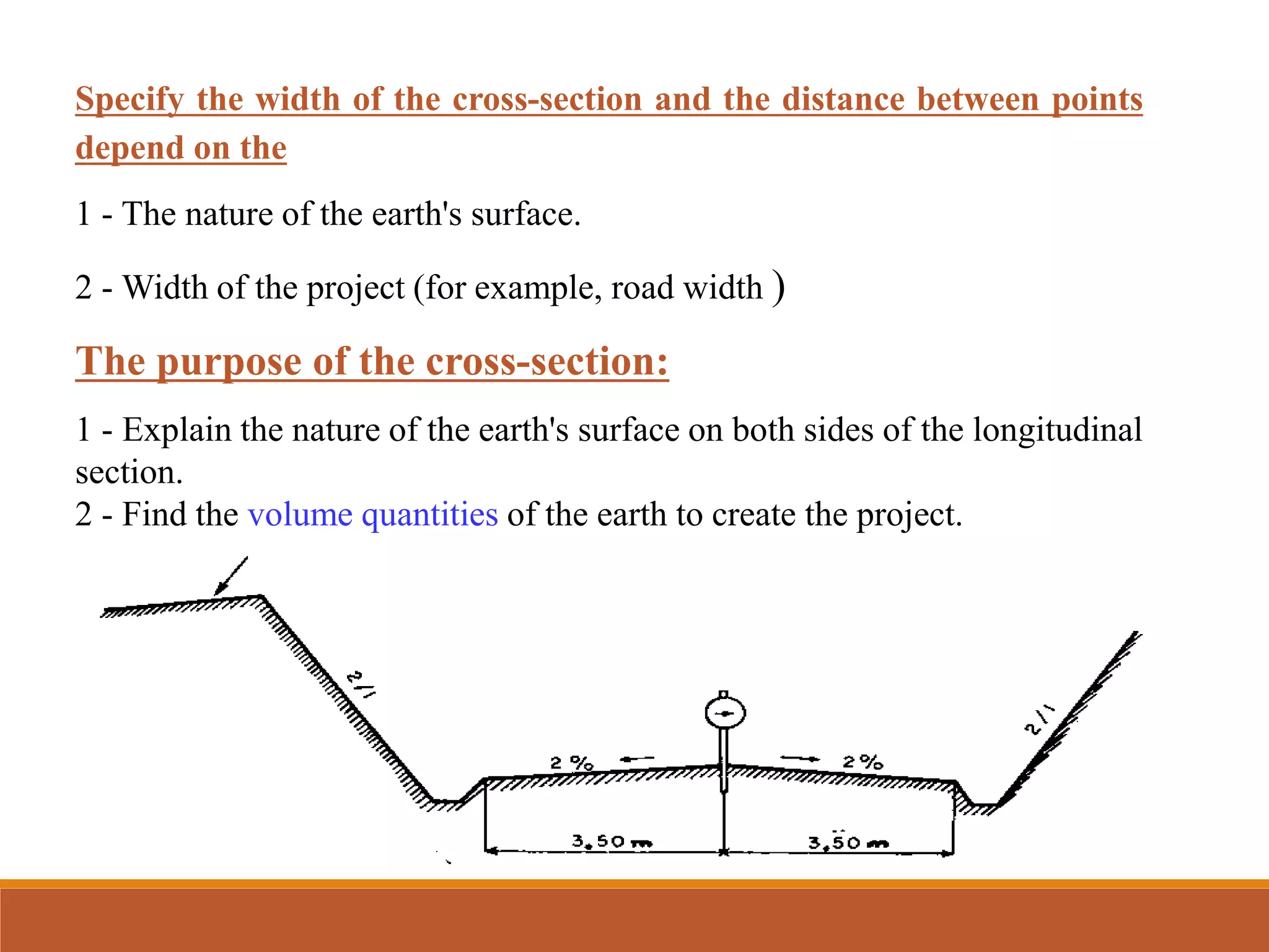

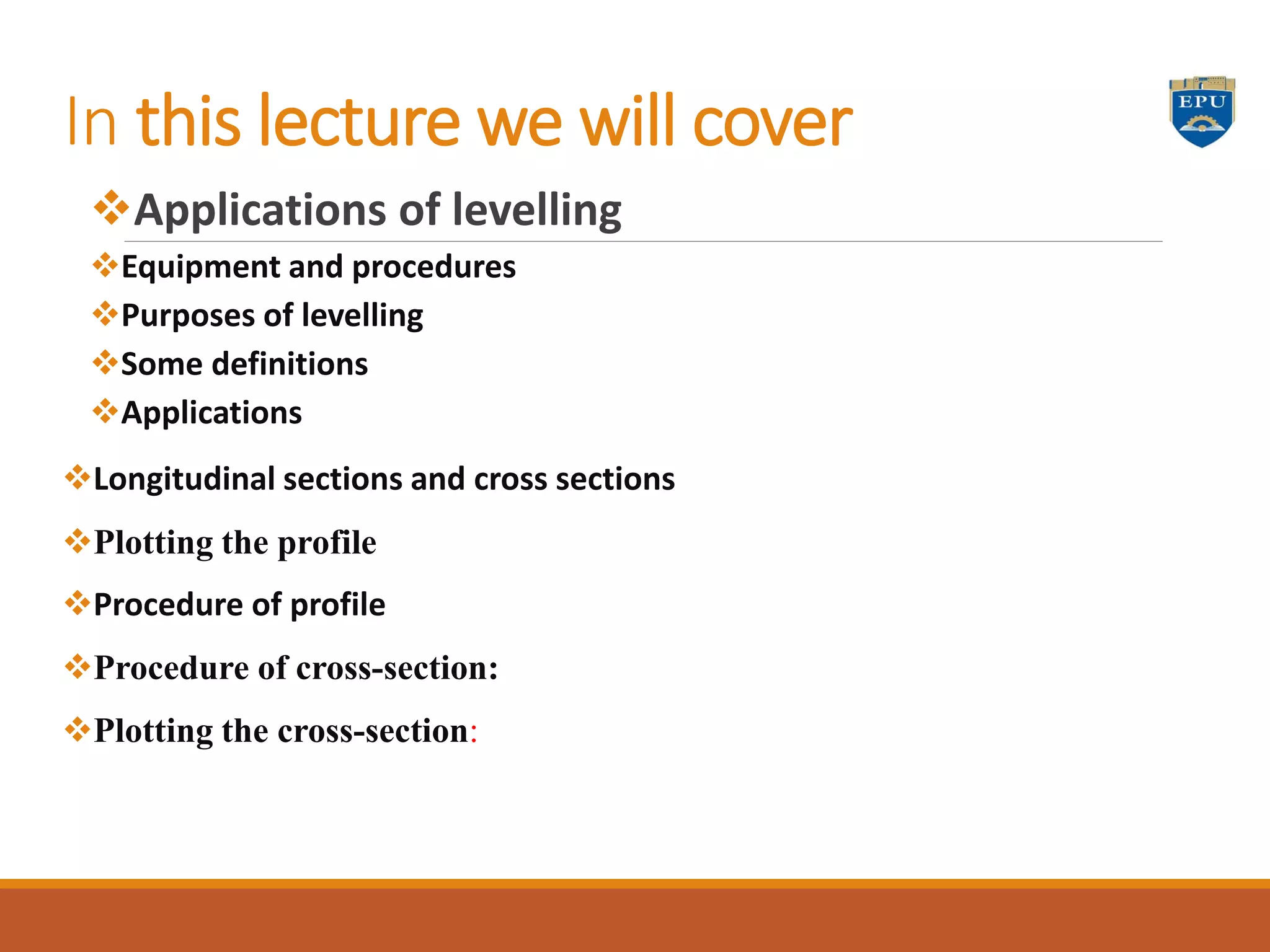
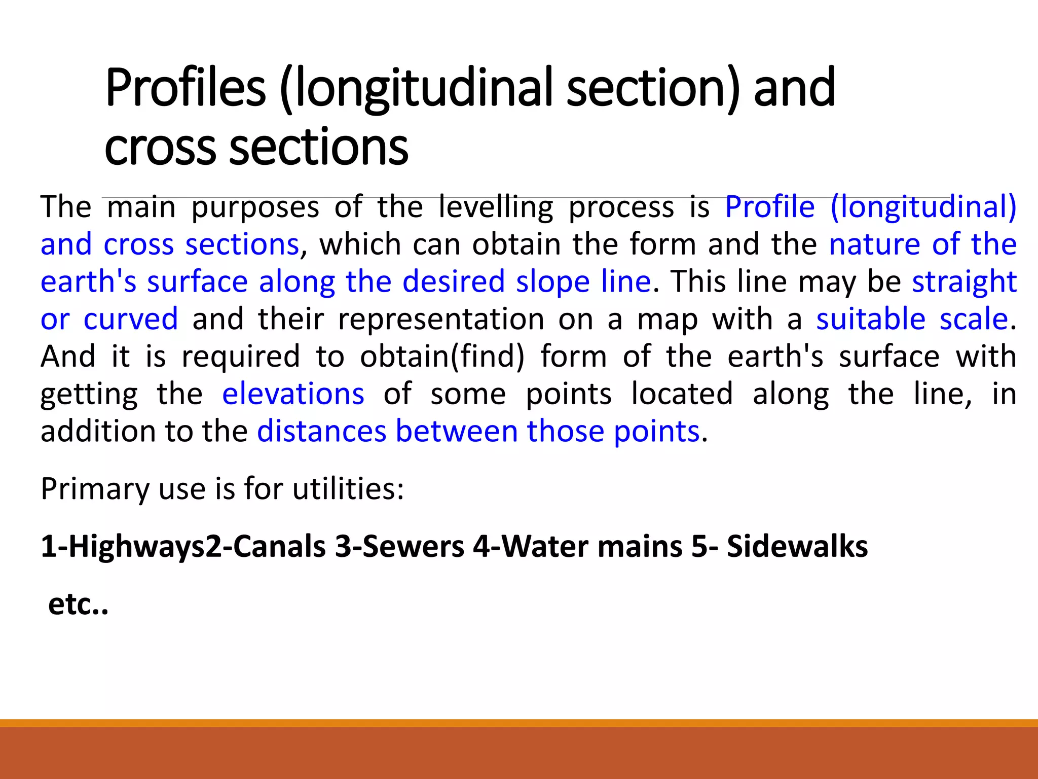
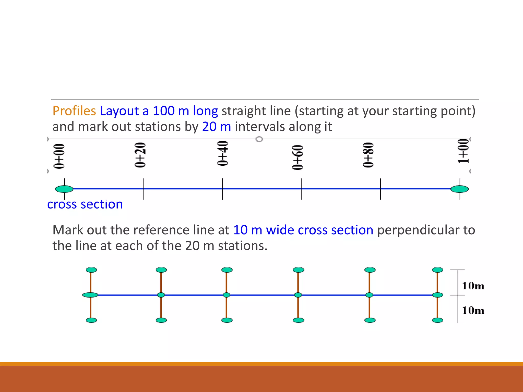
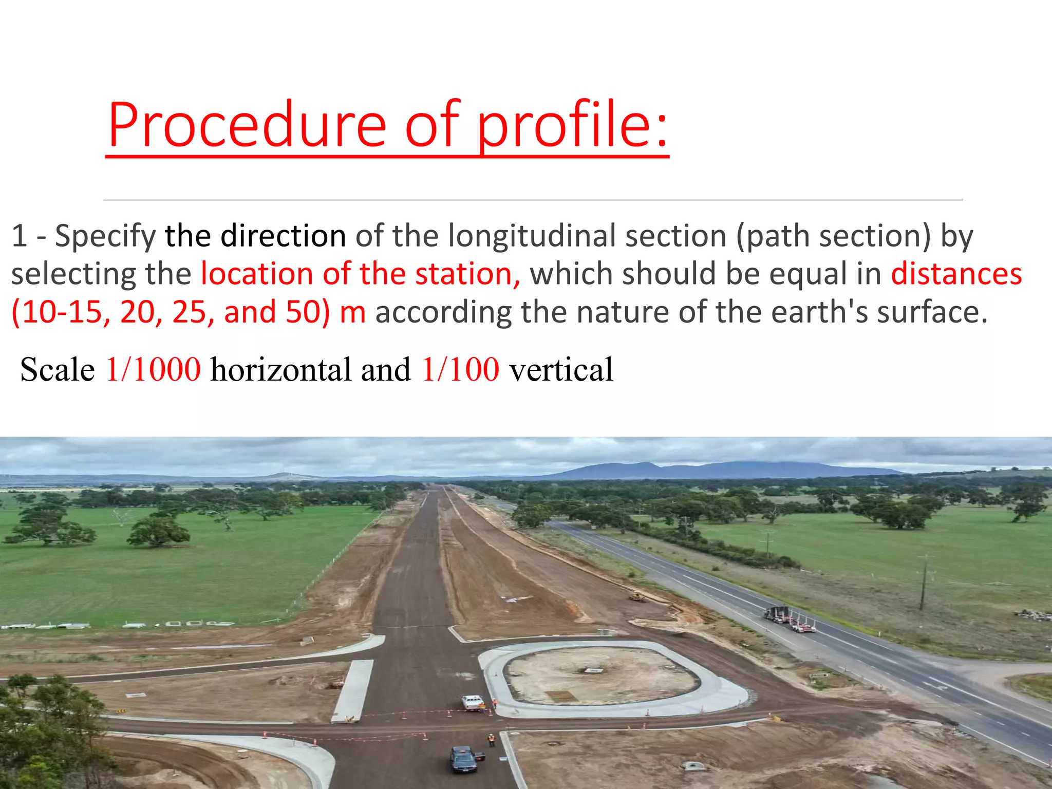
The document outlines the processes and methodologies involved in surveying engineering, focusing on longitudinal profiles and cross-sections used to represent the earth's surface. It details the equipment and procedures for levelling, including the purposes of obtaining elevation data, site procedures, and the plotting of profiles and cross-sections at designated intervals. The primary applications are in the construction of infrastructure like highways, canals, and sewers, necessitating accurate measurements and representations of topography.