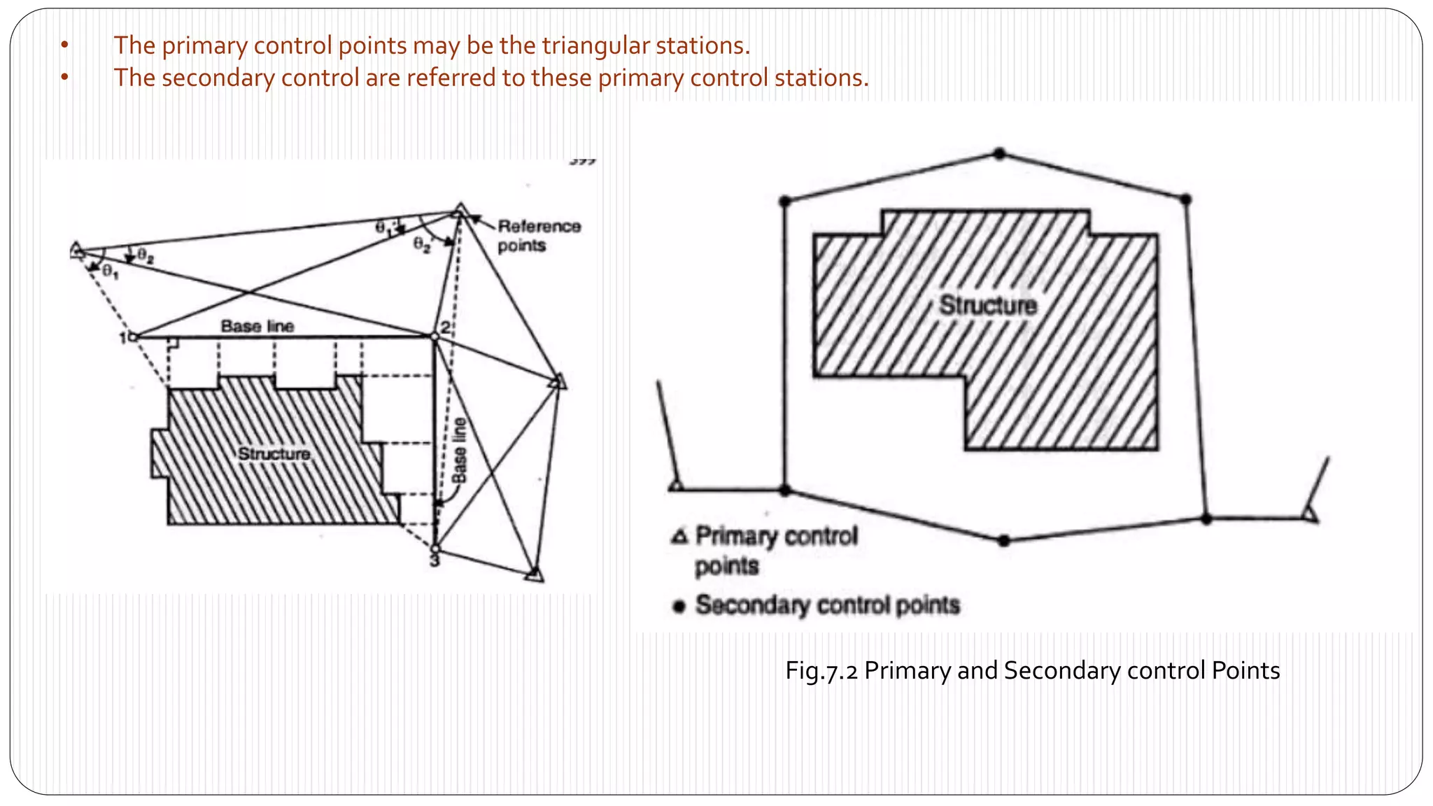
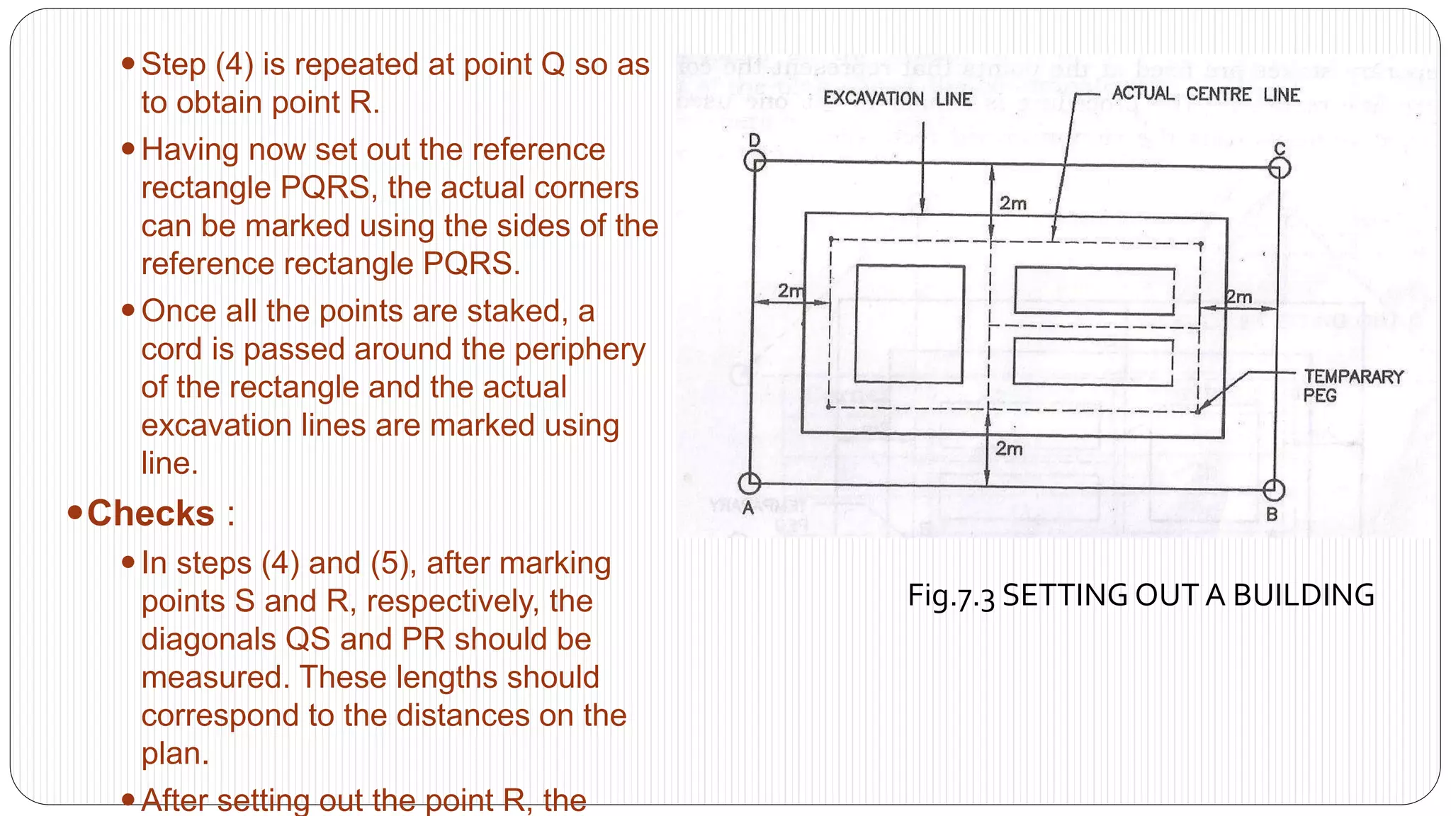
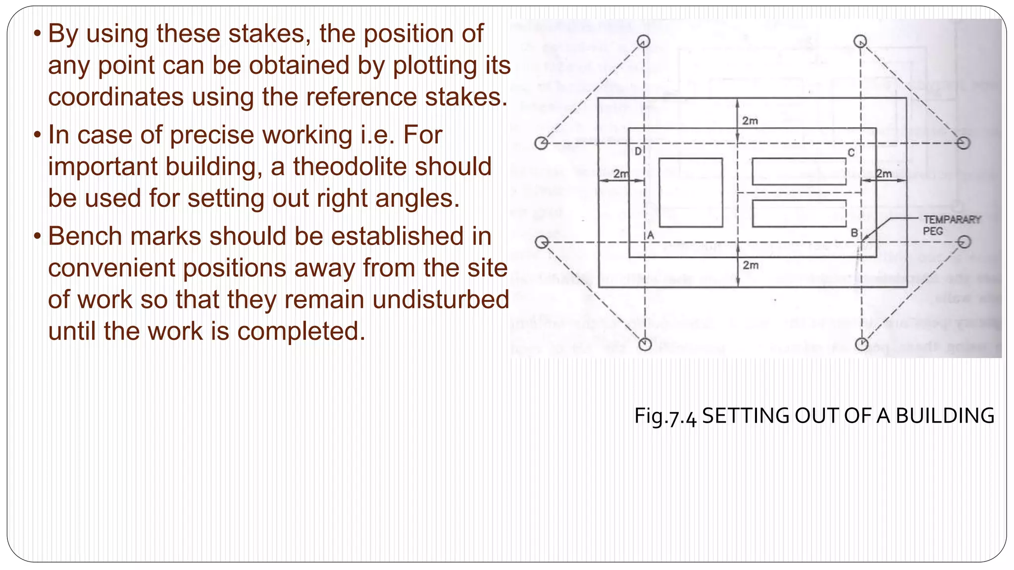
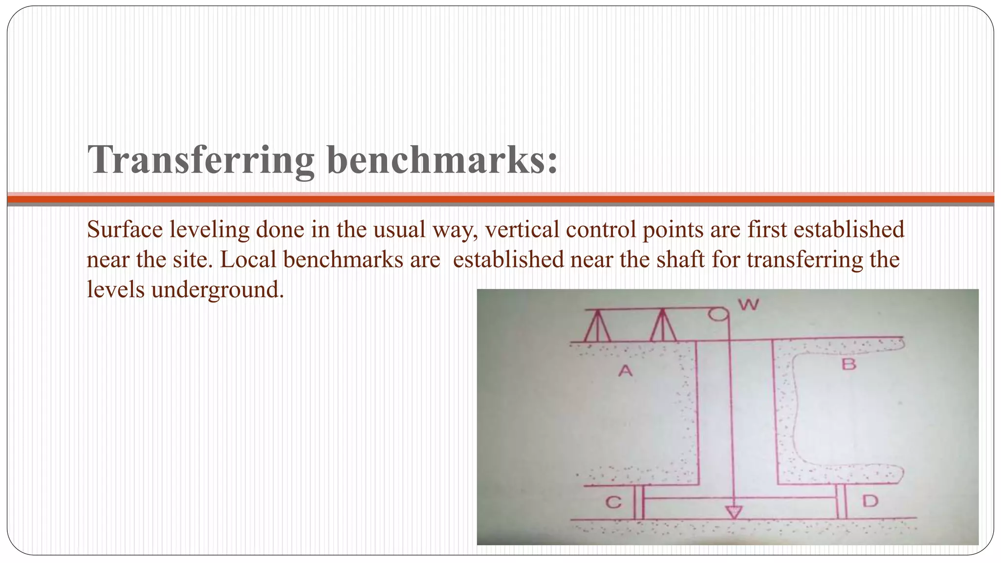
*Introduction
*Controls For Setting Out
*Horizontal control
*Vertical control
*SETTING OUT A BUILDING
*The equipment required for the job
*Method(1):-By using a Circumscribing Rectangle
*Method(2):- By using centre-line-rectangle
* Setting out of culverts
*SETTING OUT A TUNNEL
In this lecture we will cover
Applications of levelling
Equipment and procedures
Purposes of levelling
Some definitions
Applications
Longitudinal sections and cross sections
Plotting the profile
Procedure of profile
Procedure of cross-section:
Plotting the cross-section:
Prepared by:
Asst. Prof. Salar K.Hussein
Mr. Kamal Y.Abdullah
Asst.Lecturer. Dilveen H. Omar
Erbil Polytechnic University
Technical Engineering College
Civil Engineering Department
Metric Chain : It Consists of galvanized mild steel wire of 4mm diameter known as link.
It is available in 20m, 30m, 50m length which consists of 100 links.
Gunter’s Chain : A 66 feet long chain consists of 100 links, each of 0.66 feet, it is known as Gunter’s chain.
This chain is suitable for taking length in miles.
Engineer’s Chain : A 100 feet long chain consisting of 100 links each of 1 feet is known as engineer’s chain.
This chain is used to measure length in feet and area in sq.yard.
Revenue Chain : it is 33 feet long chain consisting of 16 links.
This chain is used for distance measurements in feet & inches for smaller areas.
in this presentation, we should discuss what is the need for a survey in bridge construction site and what are the needed equipment use in construction. in this presentation, you should learn about how to locate activity of bridge construction.the different method should be learning in this presentation and it more effectively. it is more helpful in your career growth.
thank you
ASWINI & SAGAR
Industrial Training at Shahjalal Fertilizer Company Limited (SFCL)MdTanvirMahtab2
This presentation is about the working procedure of Shahjalal Fertilizer Company Limited (SFCL). A Govt. owned Company of Bangladesh Chemical Industries Corporation under Ministry of Industries.
Explore the innovative world of trenchless pipe repair with our comprehensive guide, "The Benefits and Techniques of Trenchless Pipe Repair." This document delves into the modern methods of repairing underground pipes without the need for extensive excavation, highlighting the numerous advantages and the latest techniques used in the industry.
Learn about the cost savings, reduced environmental impact, and minimal disruption associated with trenchless technology. Discover detailed explanations of popular techniques such as pipe bursting, cured-in-place pipe (CIPP) lining, and directional drilling. Understand how these methods can be applied to various types of infrastructure, from residential plumbing to large-scale municipal systems.
Ideal for homeowners, contractors, engineers, and anyone interested in modern plumbing solutions, this guide provides valuable insights into why trenchless pipe repair is becoming the preferred choice for pipe rehabilitation. Stay informed about the latest advancements and best practices in the field.
Hierarchical Digital Twin of a Naval Power SystemKerry Sado
A hierarchical digital twin of a Naval DC power system has been developed and experimentally verified. Similar to other state-of-the-art digital twins, this technology creates a digital replica of the physical system executed in real-time or faster, which can modify hardware controls. However, its advantage stems from distributing computational efforts by utilizing a hierarchical structure composed of lower-level digital twin blocks and a higher-level system digital twin. Each digital twin block is associated with a physical subsystem of the hardware and communicates with a singular system digital twin, which creates a system-level response. By extracting information from each level of the hierarchy, power system controls of the hardware were reconfigured autonomously. This hierarchical digital twin development offers several advantages over other digital twins, particularly in the field of naval power systems. The hierarchical structure allows for greater computational efficiency and scalability while the ability to autonomously reconfigure hardware controls offers increased flexibility and responsiveness. The hierarchical decomposition and models utilized were well aligned with the physical twin, as indicated by the maximum deviations between the developed digital twin hierarchy and the hardware.
Welcome to WIPAC Monthly the magazine brought to you by the LinkedIn Group Water Industry Process Automation & Control.
In this month's edition, along with this month's industry news to celebrate the 13 years since the group was created we have articles including
A case study of the used of Advanced Process Control at the Wastewater Treatment works at Lleida in Spain
A look back on an article on smart wastewater networks in order to see how the industry has measured up in the interim around the adoption of Digital Transformation in the Water Industry.
3. Introduction
Setting out is the process of transferring the distance from the
plan already prepared, to the ground before starting a construction.
The plan as designed and prepared is set out on the ground in
the correct position.
The branch of surveying dealing with the setting out on the
ground is known as construction surveying.
4. Aims :-
-Understand the roles of the various different types of personnel who are involved in
the setting out process
-Understand the aims of setting out
-Refer to the different types of plans that may be used in the setting out process
-Appreciate the good working practices that should be undertaken in order that the
aims of setting out can be achieved
-Understand the procedures required to ensure that the horizontal and vertical
control requirements of setting out operations can be met
-Set out design points on site by a number of methods
-Apply horizontal and vertical control techniques to second-stage setting out
operations
-Appreciate the application of laser instruments in surveying and setting out
5. Controls For Setting Out
The setting out of work required the following two controls:
1. Horizontal control
2. Vertical control
6. • It consist of establishing reference marks of known plan
positions from which horizontal distances are measured for
setting out.
• The control points are generally used to establish a base line
near one face of the structure.
• The setting out is done by taking measurements from the base
line.
• Horizontal control can be achieved by establishing reference
grid.
• The grid which is used for actual setting out of the salient
Horizontal control
7. • The primary control points may be the triangular stations.
• The secondary control are referred to these primary control stations.
Fig.7.2 Primary and Secondary control Points
8. • It consist of establishment of reference marks of known elevation
relative to some specified datum.
• All levels at the site are normally reduced to a nearby bench mark,
usually known as Master Bench Mark(MBM).
• This Master Bench Mark(MBM) is used to establish a number of
Temporary Bench Mark(TBM).
Vertical control
9. SETTING OUT A BUILDING
The foundation plan of the building is usually supplied or it can be prepared
from the given wall plan of the building and size foundations for different wall.
Setting out of a building involves the transfer of the foundation plan frim paper
into the actual size. The object of setting out a building is to provide the builder
with clearly defined outlines for excavations.
10. The equipment required for the job are :
● A 30 m steel tape
● Two metallic tapes (15 m or 30 m)
● A long cord
● A plumb-bob
● Stakes or pegs
● Nails
● A hammer
11. It is of litter use to set the pegs or stakes at the exact position of each of the
corners of the building as they would be dug out while excavating the foundations.
It is therefore advisable to first set out a reference rectangle either out side the
limits of the excavation or along the centre lines of the outside walls of the building
and then to locate each centre by means of co-ordinates with reference to the
sides of this rectangle.
Both the methods of forming reference rectangle and setting out the building are
described below.
● Method(1):-Setting out building by circumscribing rectangle
● Method(2):-Setting out building by centre-line-rectangle
12. Method(1):-By using a Circumscribing
Rectangle:
Since stakes cannot be set at the exact corner points of a building, these are set at the
corners of a bigger rectangle circumscribing the actual building. Any suitable distance of
the outer rectangle from the building can be chosen, but a distance of usually 2 to 5 m is
considered to be ideal. The actual procedure consists of the following steps :
Procedures:
Preparation of the foundation trench plan showing the width of the foundations
for various walls.
Temporary pegs are driven at the actual corner points of the foundation plan.
Then using these pegs as reference, a parallel line, say PQ of required length is
set out at a arbitrary selected distance from the actual centre line.
A cord is stretched between the pegs P and Q.At P, a line is set out
perpendicular to PQ.On this line, the position S is marked by setting a peg.
13. Fig.7.3 SETTING OUT A BUILDING
Step (4) is repeated at point Q so as
to obtain point R.
Having now set out the reference
rectangle PQRS, the actual corners
can be marked using the sides of the
reference rectangle PQRS.
Once all the points are staked, a
cord is passed around the periphery
of the rectangle and the actual
excavation lines are marked using
line.
Checks :
In steps (4) and (5), after marking
points S and R, respectively, the
diagonals QS and PR should be
measured. These lengths should
correspond to the distances on the
plan.
After setting out the point R, the
14. Method(2):- By using centre-line-rectangle
In this method rectangle formed by the centre lines of the outer walls of
the building is used.
Procedure
The reference rectangle formed by centre lines of the out side walls of
the building as shown in fig. Is known as centre line rectangle. The
corners are located by measuring their co-ordinates with reference to
the sides of this rectangle. The temporary stakes are fixed at these
points.
Since these pegs are not permanent and will be lost during excavation,
the sudes of the centre line rectangle are produced on both the sides
15. Fig.7.4 SETTING OUT OF A BUILDING
• By using these stakes, the position of
any point can be obtained by plotting its
coordinates using the reference stakes.
• In case of precise working i.e. For
important building, a theodolite should
be used for setting out right angles.
• Bench marks should be established in
convenient positions away from the site
of work so that they remain undisturbed
until the work is completed.
16. Setting out of culverts
Setting out of culvert involves locating the corners of the abutments and the spring
walls with respect to the respective centre lines of a road or railway and the
drainage nullah, stream, etc.
While designing the culvert, the designer uses these centre lines as axes of co-
ordinates and their point of intersection is taken as the origin. A detailed tracing of
the plan shows the co-ordinate of the corners of abutments and the wing walls in a
tabular form.
17. corner easting northing
a O1 1a
b O2 2b
c O4 4c
d O3 3d
e O1 1e
f O2 2f
g O4 4g
h O3 3h
Fig.7.5 SETTING OUT OF A CULVERTS
18. Setting out a culvert is simple because there is only one span and
the flow of water is less.
If the flow of water is more, it can be easily diverted.
For bridges, flow of water can not be diverted and length may be
very long.
Due to above reasons, the setting out can not be carried out from
the centre of the bridge. So, it is not easy to setting out BRIDGES
19. Operations for the Setting out Bridges
Setting out a culvert is simple because there is only one span and the flow of water is
less.
If the flow of water is more, it can be easily diverted.
For bridges, flow of water can not be diverted and length may be very long.
Due to above reasons, the setting out can not be carried out from the centre of the
bridge. So, it is not easy to setting out BRIDGES.
The setting of bridge involves:
Determination of the length of the center Line
Determination of the Location of piers.
20. Determination of the length of the Center line:
The length of the bridge is required to be measure along the centre line.
The length of the long bridge is usually determined by triangulation.
If the P & Q are the points on the opposite banks on the centre line of the
road.
To find the length of the bridge following methods are used.
I. Method -I : Triangulation
II. Method -II : Quadrilateral method
21. Method – 1 : The steps involved are:-
Set out a line perpendicular to AB and measure AD accurately.
With the theodolite at point D and using the method of repetition, measure of
angle ADB = Ѳ
Then, tan Ѳ = AB/AD.
AB = AD tan Ѳ
To check the length AB, set out a line BC perpendicular to AB at point B.
Measure the length BC and angle BCA = α
Then, tan α = AB
BC.
AB = BC tan α.
If two distances are almost equal the mean of the two is taken as the length of
the centre line, otherwise the procedure is repeated.
22. base line
B α C
centre line of bridge River
A Ѳ D
Fig.7.6SETTING OUT OF A BRIDGE
23. Method 2. The steps involved are:
Set out lines AD and BC, perpendicular to AB.
Join CD, Ac and Bd. Measure these lines AD and BC and eight angles
accurately.
Calculate the length of AD from the measured length from the measured length
of BC and the angles, and compare it with the measured value. The difference
between the two should be less than 1 in 5000.
Then calculate the length of AB from the known angles and the base lines.
24. B base line C
River
Base line D
Fig.7.7SETTING OUT OF A BRIDGE
25. Location of piers
After the length of the bridge is measured, mark the position of central points of piers
along the centre line on the plan.
The pier are located by intersections of sight from the ends of the base line by the
following methods :
a) First method
b) Second method
26. Method 1 :-
After accurately measuring the length of the centre line AB, base lines are
laid out on each bank, perpendicular to Ab. Let it be required to fix the
positions of piers p1 and p2.
Compute the angles ADP1, ADP2, BCP1, BCP2 from the known length of
the base lines and angles BAD & CBA.
Direct the transit at A to B, and set the angle ADP1 with the transit at D. The
intersection of these two lines of sight gives the position of the central point
P1, sly. Locate the second point P2.
The location of p1 and p2 maybe checked by setting two transits at B and C.
28. Method 2
Calculate the length of the centre line AB and mark the positions of P1 and P2
on the plan.
Set up the base line at A and B, and perpendicular to AB.
Measure the distance AP1 and AP2, BP1 & BP2 from the plan and mark them
n base line at A and B respectively.
Set up the thedolite at P1 on the base line B.
Locate the centre point at P1 of the pier by simultaneously sighting from both
the points of P1.
Similarly, locate the central point P2 of the second pier.
Shift the instrument to the corresponding point of the opposite side of the
centre line AB and locate P1 and P2 in the same way.
If the points P1 and P2 are located in the same position as before, the work is
correct, otherwise repeat the process.
29. P1 P2 B P2 P1
45
45
p2
River
p1
P2 P1 A P1 P2
Fig.7.9SETTING OUT OF A PIER
30. SETTING OUT A TUNNEL
Tunnel surveying consists of two surveys surface survey and underground survey, surface
survey done in the usual way. As the terrain near the tunnel is likely to be mountainous and
difficult, careful surveying required to get the proper alignment of the tunnel.
In setting out tunnels, a major problem is the transfer of surface alignment and levels to the
underground tunnel base. The alignment and levels have to be transferred to points several
meters below the surface .
31. The setting out of a tunnel consists of the following operations:
I. Obtaining the alignment of the center line of the proposed
tunnel in the usual way.
II. Determination of the correct length of the tunnel.
III. Establishing permanent stations marking the center line of the
tunnel.
32. Transferring alignment:
The transfer the surface alignment to a point inside the tunnel the following procedure is
adopted.
Make a vertical shaft from the surface to the tunnel.
On the top of the shaft, lay two wooden beams A
and B at right angles to the alignment of the shaft.
A theodolite is set up at a predetermined station on
the center line marked on the ground surface and an
another station is sighted, again on the center line it
self.
33. The center line is then care fully set up on the beams by repetitive observing and
averaging.
Make a vertical shaft from the surface to the tunnel. On the top of the shaft, lay two
wooden beams A and B at right angles to the alignment of the shaft.
A theodolite is set up at a predetermined station on the center line marked on the
ground surface and an another station is sighted, again on the center line it self.
The center line is then care fully set up on the beams by repetitive observing and
averaging.
Hang two heavy plumb bobs using steel wires from points A and B marked on the
wooden beams.
You may also keep the plumb bobs in oil or water to keep them from swaying due to
minor air flow.
The theodolite is transferred to the bottom of the shaft. Align the line of sight of the
theodolite with the theodolite with the two wires after a number of trials.
Once the alignment is available, mark the points along this direction on the roof and
on the ground with permanent markers, drilled in the roof.
34. Transferring benchmarks:
Surface leveling done in the usual way, vertical control points are first established
near the site. Local benchmarks are established near the shaft for transferring the
levels underground.
35. The following procedure is adopted.
A steel wire loaded with a weight of 5-10 kg is passed over a pulley at the top of
the shaft and is then lowered into the shaft.
Two fine wire AB and CD are stretched at the top and bottom of the shaft
respectively.
The steel wire lowered into the shaft is so adjusted that it is in contact with both the
wire AB and CD.
Mark this hung wire at the level of the two horizontal wires accurately by a chalk
stretch the hung wire fully and keep the horizontal wires taut.
The wire is pulled out from the shaft and is stretched on the ground.
The distance between the two marks, on the wire, is measured using a measuring
tape and this gives the reduce level of the bottom of the shaft. Mark this point.