Downloaded 118 times
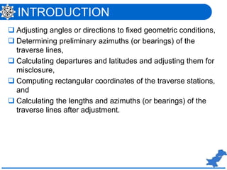
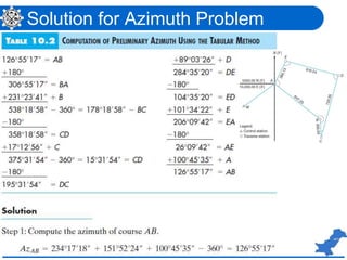
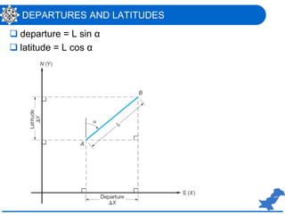

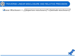
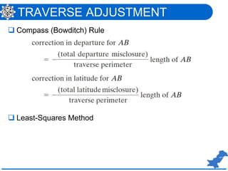
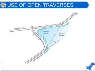


The lecture by Dr. Mahmood Arshad covers the methods for adjusting angles in traverse computations, including balancing angles, computing preliminary azimuths, and correcting for misclosure. It also discusses alternative methods for calculations, such as the least-squares method and the application of software for traverse computations. Examples and solutions are provided to illustrate the concepts presented.