Downloaded 141 times


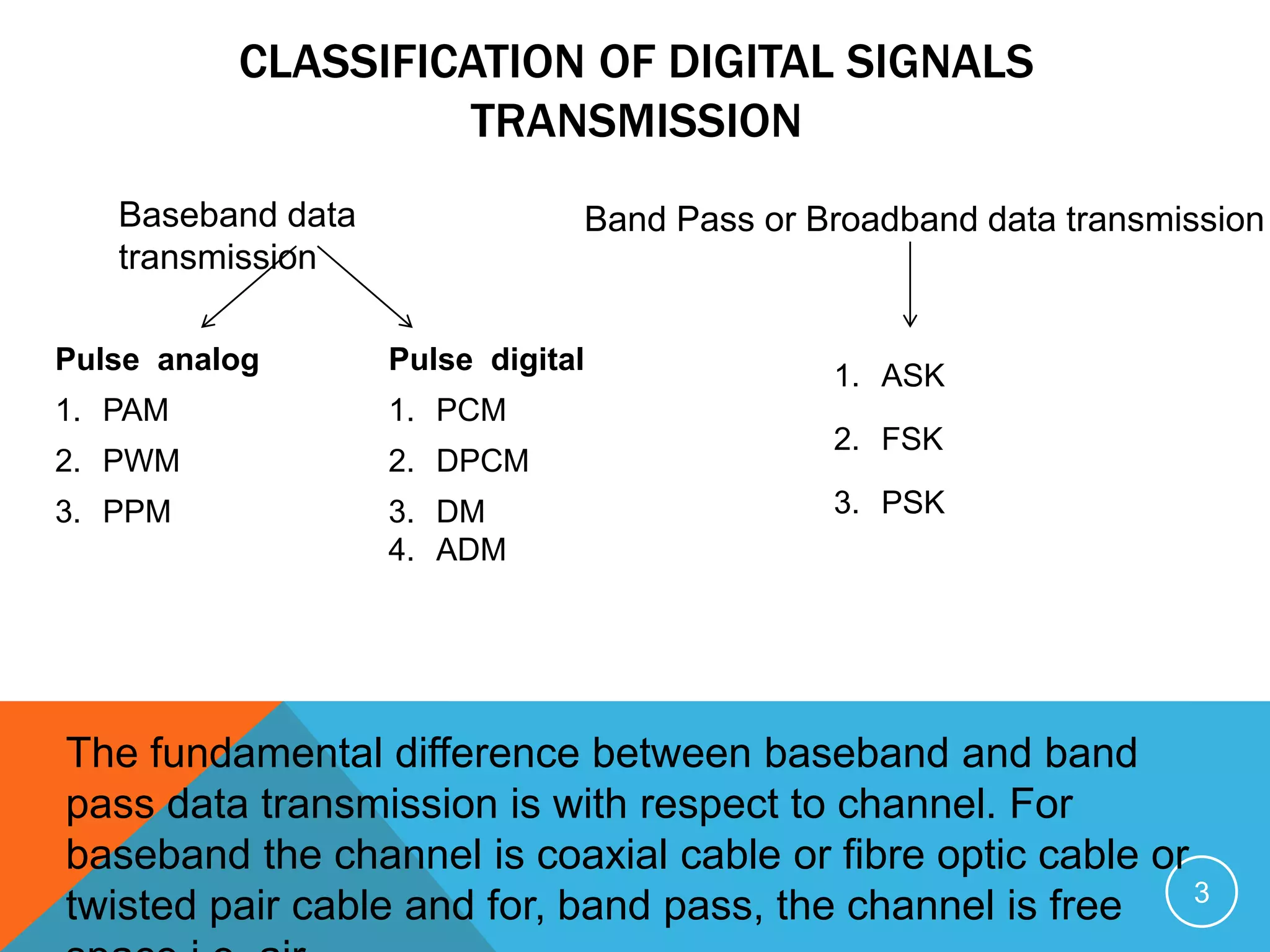
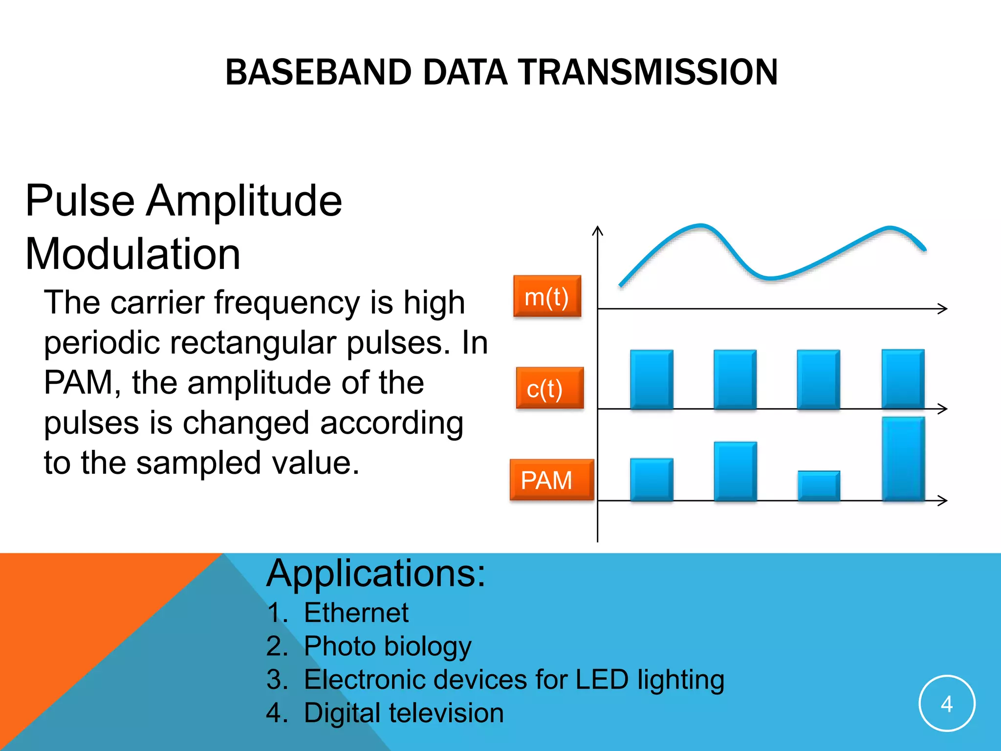

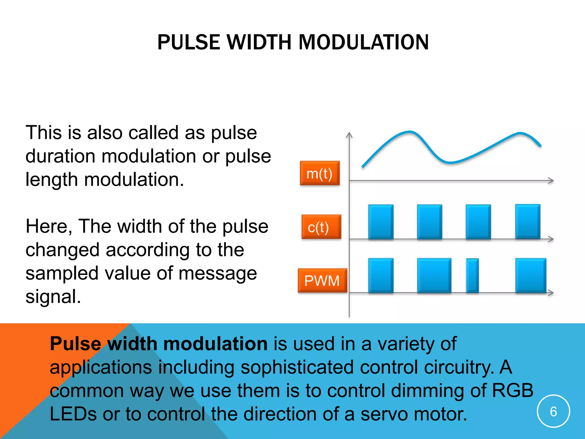
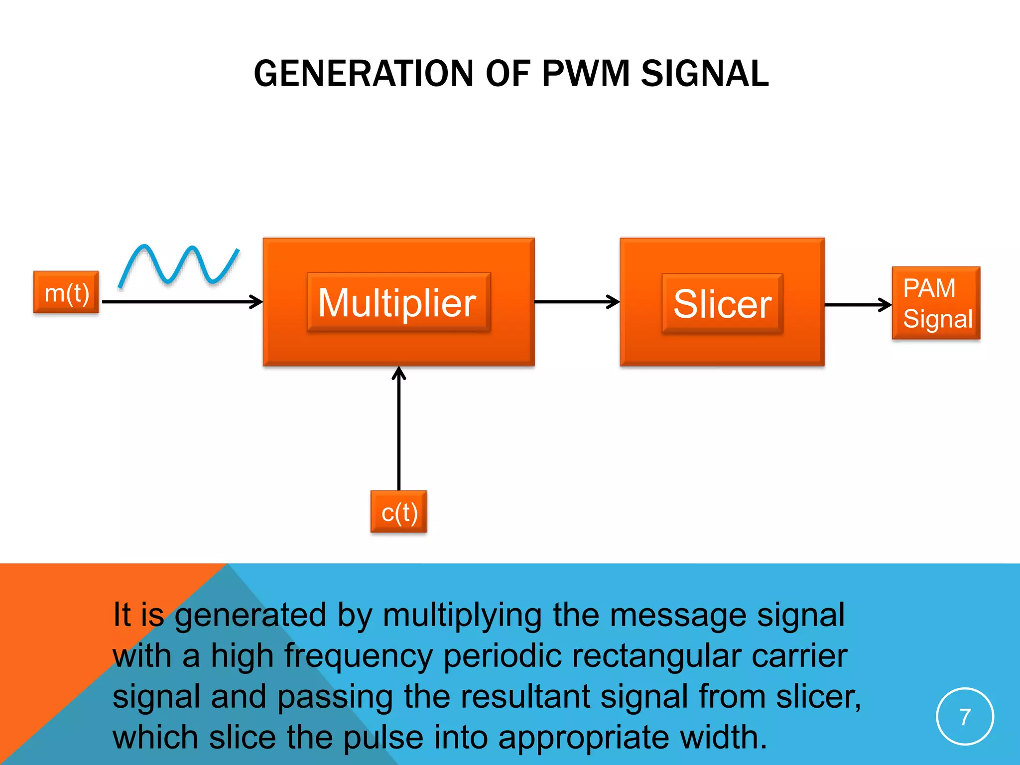


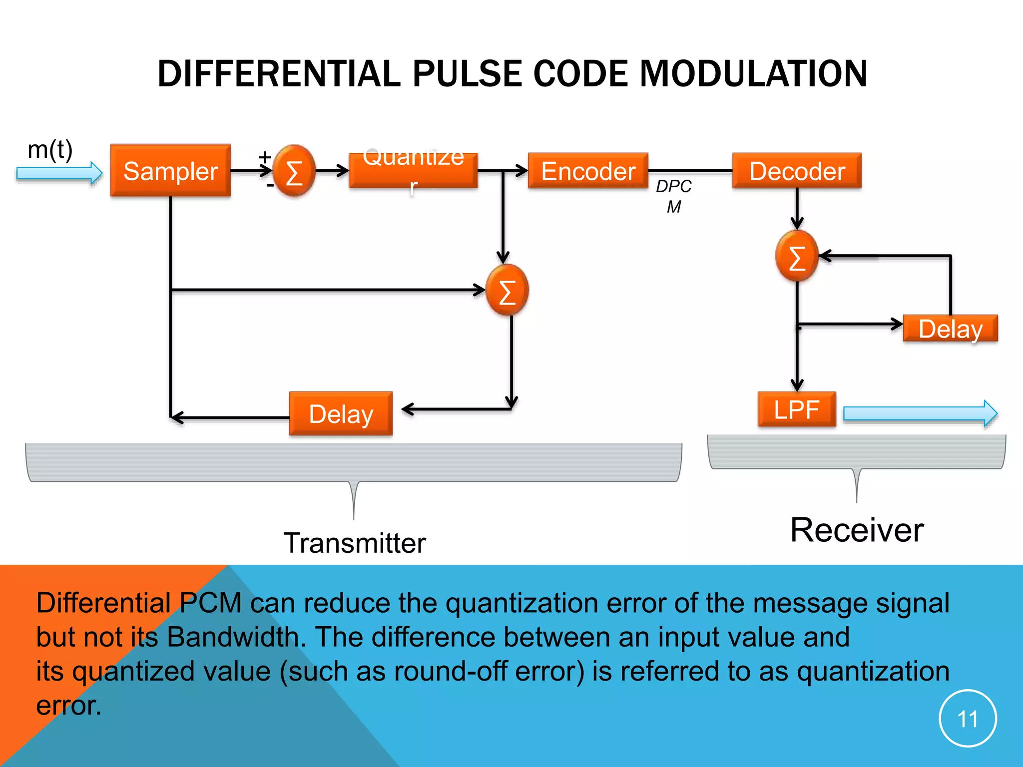


The document discusses various types of digital signal transmission, categorizing them into baseband and bandpass data transmission methods. It explains modulation techniques such as Pulse Amplitude Modulation (PAM), Pulse Width Modulation (PWM), and Pulse Position Modulation (PPM), along with their applications in telemetry and communication systems. Additionally, it covers advanced techniques like Differential Pulse Code Modulation (DPCM) and Delta Modulation (DM), and their roles in reducing bandwidth and quantization errors.