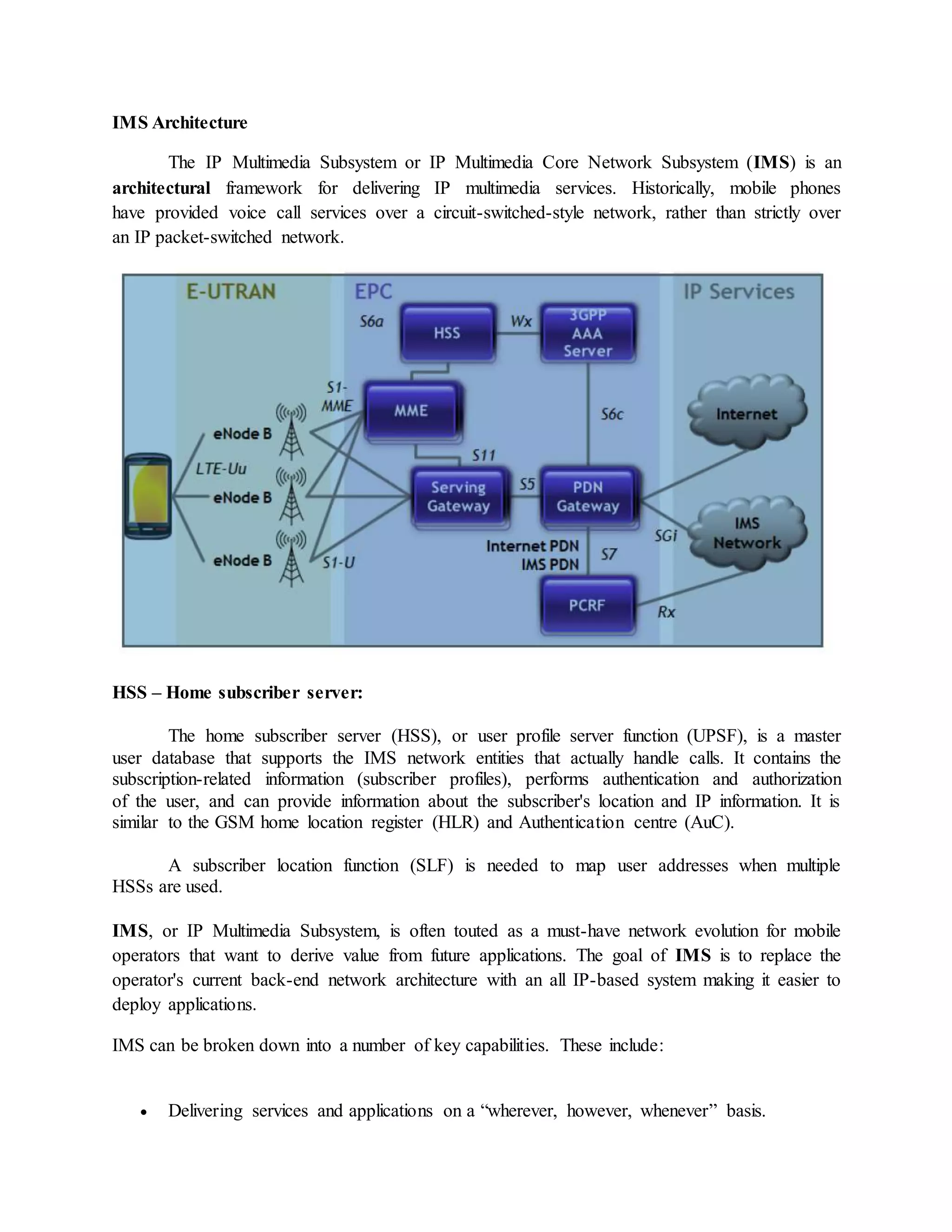
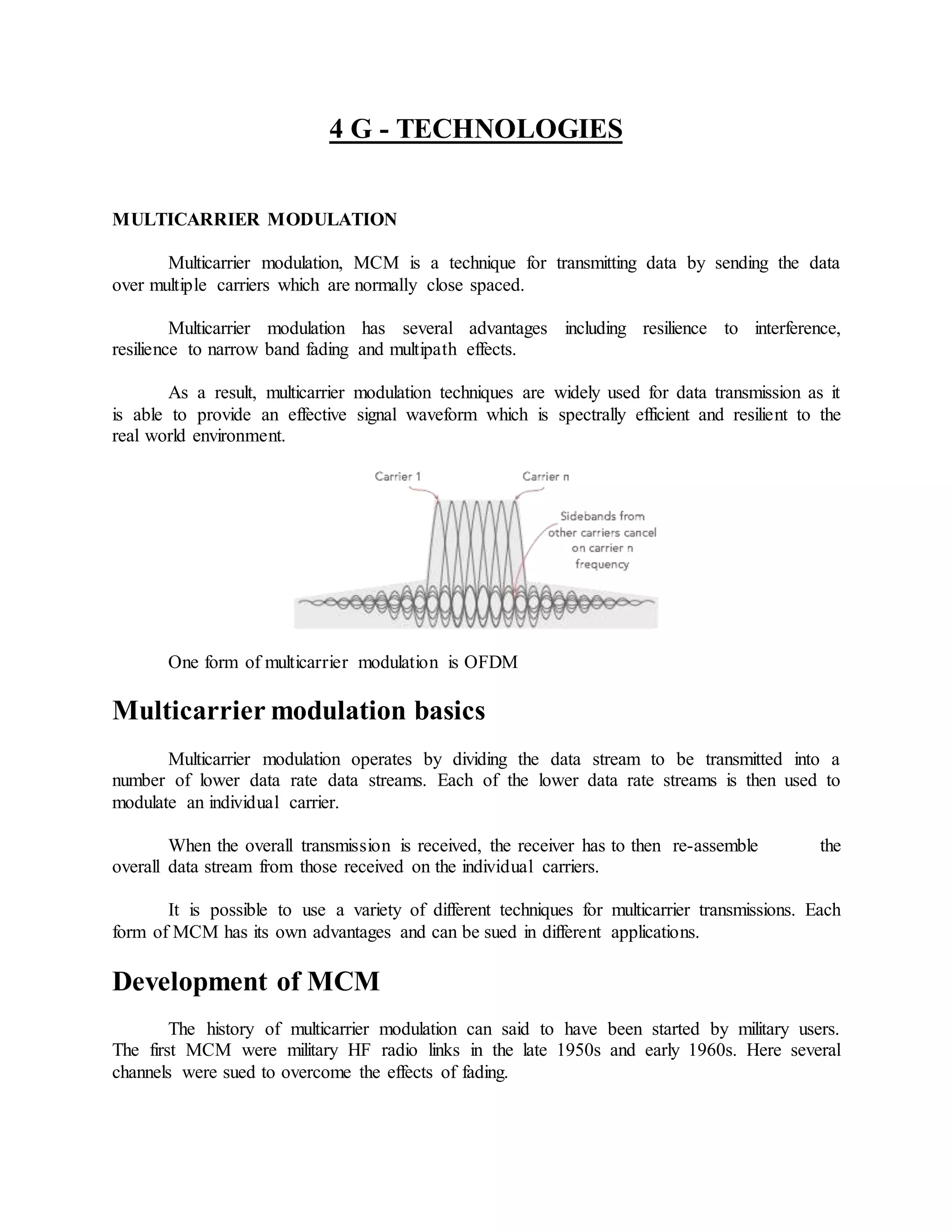
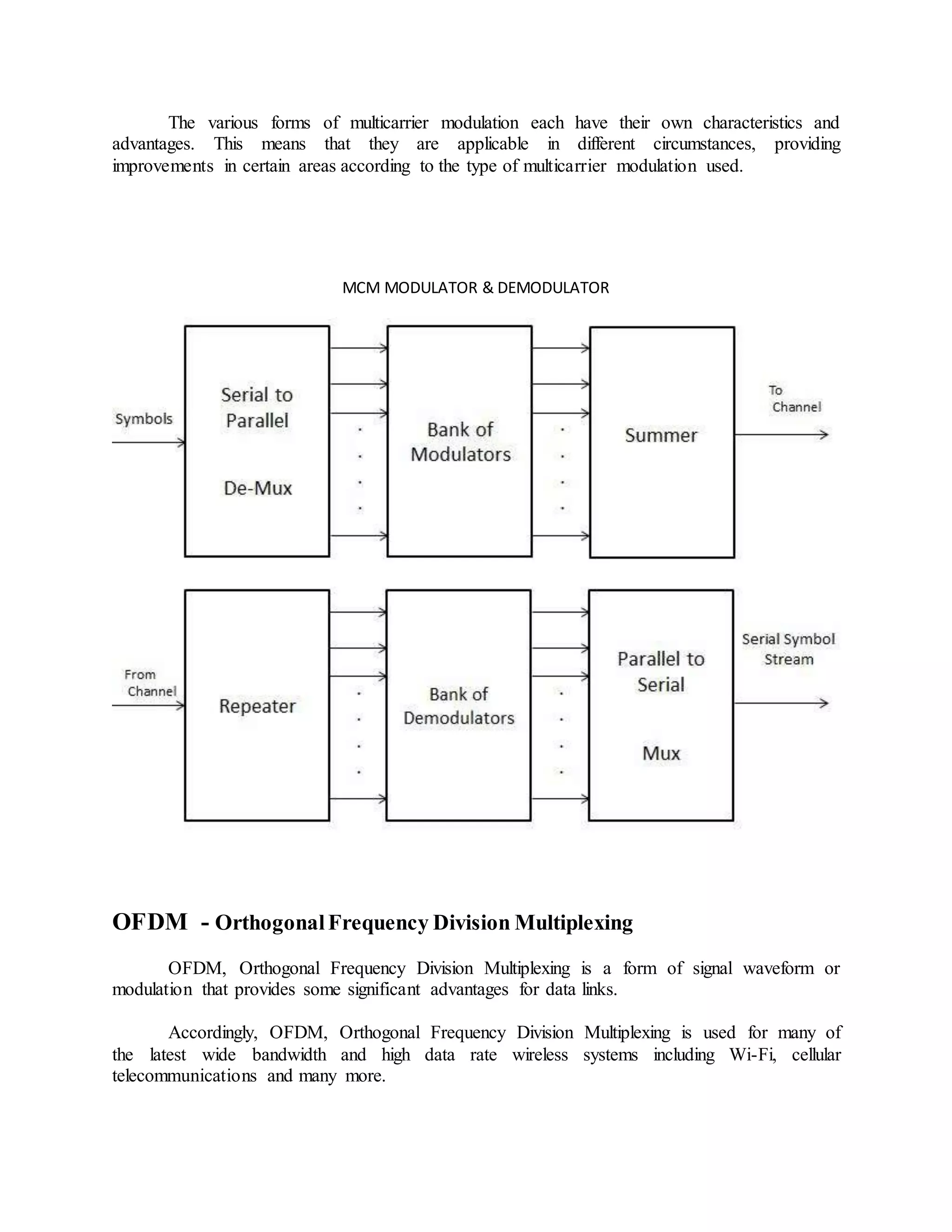
SlideShare a Scribd company logo
4 G - TECHNOLOGIES
MULTICARRIER MODULATION
Multicarrier modulation, MCM is a technique for transmitting data by sending the data
over multiple carriers which are normally close spaced.
Multicarrier modulation has several advantages including resilience to interference,
resilience to narrow band fading and multipath effects.
As a result, multicarrier modulation techniques are widely used for data transmission as it
is able to provide an effective signal waveform which is spectrally efficient and resilient to the
real world environment.
One form of multicarrier modulation is OFDM
Multicarrier modulation basics
Multicarrier modulation operates by dividing the data stream to be transmitted into a
number of lower data rate data streams. Each of the lower data rate streams is then used to
modulate an individual carrier.
When the overall transmission is received, the receiver has to then re-assemble the
overall data stream from those received on the individual carriers.
It is possible to use a variety of different techniques for multicarrier transmissions. Each
form of MCM has its own advantages and can be sued in different applications.
Development of MCM
The history of multicarrier modulation can said to have been started by military users.
The first MCM were military HF radio links in the late 1950s and early 1960s. Here several
channels were sued to overcome the effects of fading.
Originally the concept of MCM required the use of several channels that were separated
from each other by the use of steep sided filters of they were close spaced. In this way,
interference from the different channels could be eliminated.
However, multicarrier modulation systems first became widely used with the introduction
of broadcasting systems such as DAB digital radio and DVB, Digital Video Broadcasting which
used OFDM, orthogonal frequency division multiplexing. OFDM used processing power within
the receiver and orthogonality between the carriers to ensure no interference was present.
Later OFDM was used for systems such as wireless / cellular telecommunications and
networking standards including WiMAX, Wi-Fi 802.11, and also LTE, the Long Term Evolution
for cellular systems.
Also other cellular systems have used multicarrier techniques to achieve high data rates
by using two or more carriers from a standard cellular system. Dual Carrier HSPA is one
example.
With new networking and cellular systems on the horizon, other multicarrier techniques
have been investigated and their use seems likely in the near future.
Multicarrier modulation systems
There are many forms of multicarrier modulation techniques that are in use of being
investigated for future use. Some of the more widely known schemes are summarised below.
 Orthogonal frequency division multiplexing, OFDM: OFDM is possibly the most
widely used form of multicarrier modulation. It uses multiple closely spaced carriers and
as a result of their orthogonality, mutual interference between them is avoided.
 Generalised Frequency Division Multiplexing, GFDM: GFDM is a multicarrier
modulation scheme that uses closed spaced non-orthogonal carriers and provides flexible
pulse shaping. It is therefore attractive for various applications such as machine to
machine communications.
 Filter Bank Multi Carrier, FBMC: FBMC is a form of multicarrier modulation scheme
that uses a specialised pulse shaping filter known as an isotropic orthogonal transform
algorithm, IOTA within the digital signal processing for the system. This scheme
provides good time and frequency localisation properties and this ensures that inter-
symbol interference and inter-carrier interference are avoided without the use of cyclic
prefix required for OFDM based systems.
 SEFDM: Spectrally efficient frequency division multiplex uses multiple carriers in the
same way as OFDM, but they are spaced closer than OFDM. However it is stil possible
to recover the data, although with a slight power penalty.
The various forms of multicarrier modulation each have their own characteristics and
advantages. This means that they are applicable in different circumstances, providing
improvements in certain areas according to the type of multicarrier modulation used.
MCM MODULATOR & DEMODULATOR
OFDM - OrthogonalFrequency Division Multiplexing
OFDM, Orthogonal Frequency Division Multiplexing is a form of signal waveform or
modulation that provides some significant advantages for data links.
Accordingly, OFDM, Orthogonal Frequency Division Multiplexing is used for many of
the latest wide bandwidth and high data rate wireless systems including Wi-Fi, cellular
telecommunications and many more.
The fact that OFDM uses a large number of carriers, each carrying low bit rate data,
means that it is very resilient to selective fading, interference, and multipath effects, as well
providing a high degree of spectral efficiency.
Early systems using OFDM found the processing required for the signal format was
relatively high, but with advances in technology, OFDM presents few problems in terms of the
processing required.
Development of OFDM
The use of OFDM and multicarrier modulation in general has come to the fore in recent
years as it provides an ideal platform for wireless data communications transmissions.
However the concept of OFDM technology was first investigated in the 1960s and 1970s
during research into methods for reducing interference between closely spaced channels. IN
addition to this other requirements needed to achieve error free data transmission in the presence
of interference and selective propagation conditions.
What is OFDM?
OFDM is a form of multicarrier modulation. An OFDM signal consists of a number of
closely spaced modulated carriers. When modulation of any form - voice, data, etc. is applied to
a carrier, then sidebands spread out either side. It is necessary for a receiver to be able to receive
the whole signal to be able to successfully demodulate the data. As a result when signals are
transmitted close to one another they must be spaced so that the receiver can separate them using
a filter and there must be a guard band between them. This is not the case with OFDM. Although
the sidebands from each carrier overlap, they can still be received without the interference that
might be expected because they are orthogonal to each another. This is achieved by having the
carrier spacing equal to the reciprocal of the symbol period.
To see how OFDM works, it is necessary to look at the receiver. This acts as a bank of
demodulators, translating each carrier down to DC. The resulting signal is integrated over the
symbol period to regenerate the data from that carrier. The same demodulator also demodulates
the other carriers. As the carrier spacing equal to the reciprocal of the symbol period means that
they will have a whole number of cycles in the symbol period and their contribution will sum to
zero - in other words there is no interference contribution.
One requirement of the OFDM transmitting and receiving systems is that they must be
linear. Any non-linearity will cause interference between the carriers as a result of inter-
modulation distortion. This will introduce unwanted signals that would cause interference and
impair the orthogonality of the transmission.
In terms of the equipment to be used the high peak to average ratio of multi-carrier
systems such as OFDM requires the RF final amplifier on the output of the transmitter to be able
to handle the peaks whilst the average power is much lower and this leads to inefficiency. In
some systems the peaks are limited. Although this introduces distortion that results in a higher
level of data errors, the system can rely on the error correction to remove them.
Key features of OFDM
The OFDM scheme differs from traditional FDM in the following interrelated ways:
 Multiple carriers (called subcarriers) carry the information stream
 The subcarriers are orthogonal to each other.
 A guard interval is added to each symbol to minimize the channel delay spread and
intersymbol interference.
OFDM advantages & disadvantages
OFDM advantages
OFDM has been used in many high data rate wireless systems because of the many advantages it
provides.
 Immunity to selective fading: One of the main advantages of OFDM is that is more
resistant to frequency selective fading than single carrier systems because it divides the
overall channel into multiple narrowband signals that are affected individually as flat
fading sub-channels.
 Resilience to interference: Interference appearing on a channel may be bandwidth
limited and in this way will not affect all the sub-channels. This means that not all the
data is lost.
 Spectrum efficiency: Using close-spaced overlapping sub-carriers, a significant OFDM
advantage is that it makes efficient use of the available spectrum.
 Resilient to ISI: Another advantage of OFDM is that it is very resilient to inter-symbol
and inter-frame interference. This results from the low data rate on each of the sub-
channels.
 Resilient to narrow-band effects: Using adequate channel coding and interleaving it is
possible to recover symbols lost due to the frequency selectivity of the channel and
narrow band interference. Not all the data is lost.
 Simpler channel equalisation: One of the issues with CDMA systems was the
complexity of the channel equalisation which had to be applied across the whole channel.
An advantage of OFDM is that using multiple sub-channels, the channel equalization
becomes much simpler.
OFDM disadvantages
Whilst OFDM has been widely used, there are still a few disadvantages to its use which need to
be addressed when considering its use.
 High peak to average power ratio: An OFDM signal has a noise like amplitude
variation and has a relatively high large dynamic range, or peak to average power ratio.
This impacts the RF amplifier efficiency as the amplifiers need to be linear and
accommodate the large amplitude variations and these factors mean the amplifier cannot
operate with a high efficiency level.
 Sensitive to carrier offset and drift: Another disadvantage of OFDM is that is sensitive
to carrier frequency offset and drift. Single carrier systems are less sensitive.
OFDM, orthogonal frequency division multiplexing has gained a significant presence in the
wireless market place. The combination of high data capacity, high spectral efficiency, and its
resilience to interference as a result of multi-path effects means that it is ideal for the high data
applications that have become a major factor in today's communications scene.
OFDM – Transmitter and Receiver
SMART ANTENNA
Smart antenna is defined as a multi-beam antennas or adaptive array beams does not
switch. Multiband antenna using a plurality of fixed beams in a sector, and in the adaptive array
antenna receiving a plurality of signals are weighted and synthesized together so that the
maximum signal to noise ratio. Compared to the fixed beam antennas, in addition to the
advantages of the antenna array is the high-gain antenna, but also provide a multiple diversity
gain. However, they require each antenna has a receiver, but also to provide a multiple diversity
gain.
Smart Antenna inhibit signal interference, automatic tracking and digital beam
adjustment and other intelligent features, the basic working principle is adjusted according to the
direction of the signal wave pattern adaptively tracking the strong signal, reduce or offset the
interference signal. Smart antennas can improve the signal to noise ratio, improve the quality of
the communication system, ease the contradiction between the growing shortage of spectrum
resources and radio communication, reduce overall system cost, so it is bound to become a key
technology 4G system. Core smart antenna is a smart algorithm, and the algorithm determines
the complexity of the circuits and transient response speed, so you need to select a good
algorithm intelligent control beam
Smart antennas using spatial division multiple access (SDMA) technology that uses the
difference in signal transmission direction, the same frequency or the same time slot, with the
signal code channel distinguish dynamically change the coverage area of the signal, so that the
main beam is aligned direction of the user, or the side lobe nulling aligned with the direction of
interfering signals, and users can automatically track and monitor changes in the environment,
provide quality uplink and downlink signal for each user, so as to suppress interference and
accurately extract the effective signal purpose.Therefore, smart antenna technology is more
suitable for a mobile communication system having a complex wave propagation environment.
In my country's 3G standard TD-SCDMA smart antenna technology is adopted.
Smart antenna has the following advantages:
1. Increase system capacity. SDMA using smart antenna technology, the use of the different
spatial directions channel segmentation, can use the same frequency without interference in
different channels at the same time, thereby increasing system capacity.
2. Reduce system interference. Smart antenna technology to beam side lobes or interference
signal nulling aligned direction, it is possible to effectively suppress interference.
3. Expand the coverage area. Because smart antenna with adaptive beam steering function, as
compared with the conventional antenna, transmission power in the same conditions, using smart
antenna signal can be transmitted to greater distances, thereby increasing coverage.
4. Reduce the cost of system construction. Because smart antenna technology to expand the
coverage area, the number of base station construction can be reduced, reducing the operator's
construction costs. The main disadvantage of smart antenna technology is the use of it will
increase the complexity of communication systems and components offer higher performance
requirements.
MIMO
Multiple-Input and Multiple-Output, or MIMO is a method for multiplying the
capacity of a radio link using multiple transmission and receiving antennas to exploit multipath
propagation.MIMO has become an essential element of wireless communication standards
including IEEE 802.11n (Wi-Fi), IEEE 802.11ac (Wi-Fi), HSPA+ (3G), WiMAX (4G), and
Long Term Evolution (4G LTE).
In wireless the term "MIMO" referred to the use of multiple antennas at the transmitter
and the receiver. In modern usage, "MIMO" specifically refers to a practical technique for
sending and receiving more than one data signal simultaneously over the same radio channel by
exploiting multipath propagation. MIMO is fundamentally different from smart antenna
techniques developed to enhance the performance of a single data signal, such as beamforming
and diversity.
MIMO can be sub-divided into three main categories:
Precoding, Spatial multiplexing (SM), and Diversity coding.
Precoding is multi-stream beamforming, in the narrowest definition. In more general terms, it is
considered to be all spatial processing that occurs at the transmitter. In (single-stream)
beamforming, the same signal is emitted from each of the transmit antennas with appropriate
phase and gain weighting such that the signal power is maximized at the receiver input. The
benefits of beamforming are to increase the received signal gain – by making signals emitted
from different antennas add up constructively – and to reduce the multipath fading effect. In line-
of-sight propagation, beamforming results in a well-defined directional pattern. However,
conventional beams are not a good analogy in cellular networks, which are mainly characterized
by multipath propagation. When the receiver has multiple antennas, the transmit beamforming
cannot simultaneously maximize the signal level at all of the receive antennas, and precoding
with multiple streams is often beneficial. Note that precoding requires knowledge of channel
state information (CSI) at the transmitter and the receiver.
Spatial multiplexing requires MIMO antenna configuration. In spatial multiplexing,[33] a high-
rate signal is split into multiple lower-rate streams and each stream is transmitted from a
different transmit antenna in the same frequency channel. If these signals arrive at the receiver
antenna array with sufficiently different spatial signatures and the receiver has accurate CSI, it
can separate these streams into (almost) parallel channels. Spatial multiplexing is a very
powerful technique for increasing channel capacity at higher signal-to-noise ratios (SNR). The
maximum number of spatial streams is limited by the lesser of the number of antennas at the
transmitter or receiver. Spatial multiplexing can be used without CSI at the transmitter, but can
be combined with precoding if CSI is available. Spatial multiplexing can also be used for
simultaneous transmission to multiple receivers, known as space-division multiple access or
multi-user MIMO, in which case CSI is required at the transmitter.[34] The scheduling of
receivers with different spatial signatures allows good separability.
Diversity coding techniques are used when there is no channel knowledge at the transmitter. In
diversity methods, a single stream (unlike multiple streams in spatial multiplexing) is
transmitted, but the signal is coded using techniques called space-time coding. The signal is
emitted from each of the transmit antennas with full or near orthogonal coding. Diversity coding
exploits the independent fading in the multiple antenna links to enhance signal diversity. Because
there is no channel knowledge, there is no beamforming or array gain from diversity coding.
Diversity coding can be combined with spatial multiplexing when some channel knowledge is
available at the receiver.
Multi-antenna types
Multi-antenna MIMO (or Single user MIMO) technology has been developed and implemented
in some standards, e.g., 802.11n products.
 SISO/SIMO/MISO are special cases of MIMO
o Multiple-input and single-output (MISO) is a special case when the receiver has a
single antenna.
o Single-input and multiple-output (SIMO) is a special case when the transmitter
has a single antenna.
o Single-input single-output (SISO) is a conventional radio system where neither
transmitter nor receiver has multiple antenna.
IMS Architecture
The IP Multimedia Subsystem or IP Multimedia Core Network Subsystem (IMS) is an
architectural framework for delivering IP multimedia services. Historically, mobile phones
have provided voice call services over a circuit-switched-style network, rather than strictly over
an IP packet-switched network.
HSS – Home subscriber server:
The home subscriber server (HSS), or user profile server function (UPSF), is a master
user database that supports the IMS network entities that actually handle calls. It contains the
subscription-related information (subscriber profiles), performs authentication and authorization
of the user, and can provide information about the subscriber's location and IP information. It is
similar to the GSM home location register (HLR) and Authentication centre (AuC).
A subscriber location function (SLF) is needed to map user addresses when multiple
HSSs are used.
IMS, or IP Multimedia Subsystem, is often touted as a must-have network evolution for mobile
operators that want to derive value from future applications. The goal of IMS is to replace the
operator's current back-end network architecture with an all IP-based system making it easier to
deploy applications.
IMS can be broken down into a number of key capabilities. These include:
 Delivering services and applications on a “wherever, however, whenever” basis.
 Enabling service providers to offer multimedia services across both next-gen, packet-
switched networks and traditional circuit-switched networks
 Providing pipes and protocols onto which service providers can attach applications.
 Using open standards so that hardware and software components from different vendors
can be integrated together.
 Supporting a variety of real-time, interactive services and applications.
A number of important trends are driving IMS adoption and the communications convergence
that it’s enabling. These include:
 Voices services are becoming commodities
 The growing importance of service bundling and differentiation
 A shift to mobile services that are available anywhere and anytime
 The use of networks and service delivery platforms that are access-agnostic
 Industry embracing of open computing and networking standards
 The use of IP as an end-to-end transport for all types of services (voice, video, TV, etc.)
IMS offers a variety of benefits to carriers and service providers. Some of those benefits include:
 Works with any access network
 Promises to support virtually any IP-based service
 Drives interoperability based on open standards
 Reuse of components accelerates the roll-out of new revenue streams
 Can lower the cost of developing, introducing and maintaining services
Functions of IMS
IMS core elements are primarily responsible for handing (routing) Session Initiation
Protocol (SIP) traffic, as the signaling mechanism of choice for public communications network
infrastructures. The Diameter protocol is also widely employed, within the IMS core, for policy
control and billing.
Features of IMS
IMS can be broken down into a number of key capabilities. These include: Delivering
services and applications on a “wherever, however, whenever” basis. Enabling service providers
to offer multimedia services across both next-gen, packet-switched networks and traditional
circuit-switched networks.
LTE - Long-Term Evolution
A standard LTE system architecture consists of an Evolved UMTS Terrestrial Radio
Access Network, more commonly known as E-UTRAN, and the System Architecture Evolution,
also known as SAE. SAE's main component is the Evolved Packet Core, also known as an EPC.
Evolved Packet Core (EPC) is a framework for providing converged voice and data on a 4G
Long-Term Evolution (LTE) network
LTE entities
EPC entities
LTE interfaces
LTE Protocol Stacks
Based on the EPS entities and interfaces, the LTE protocol stacks for the user
plane and control plane are described.
User plane protocol stacks
Figure shows the user plane protocol stacks for the LTE network reference model
shown in Figure 1. The functions of the key layers of the protocol stacks are briefly
described below.
LTE user plane protocol stacks
LTE-Uu interface
 PDCP: The PDCP protocol supports efficient transport of IP packets over the radio link. It
performs header compression, Access Stratum (AS) security (ciphering and integrity
protection) and packet re-ordering/retransmission during handover.
 RLC: In the transmitting side, the RLC protocol constructs RLC PDU and provides the
RLC PDU to the MAC layer. The RLC protocol performs segmentation/concatenation of
PDCP PDUs during construction of the RLC PDU. In the receiving side, the RLC protocol
performs reassembly of the RLC PDU to reconstruct the PDCP PDU. The RLC protocol
has three operational modes (i.e. transparent mode, acknowledged mode and
unacknowledged mode), and each offers different reliability levels. It also performs packet
(the RLC PDU) re-ordering and retransmission.
 MAC: The MAC layer lies between the RLC layer and PHY layer. It is connected to the
RLC layer through logical channels, and to the PHY layer through transport channels.
Therefore, the MAC protocol supports multiplexing and de-multiplexing between logical
channels and transport channels. Higher layers use different logical channels for different
QoS metrics. The MAC protocol supports QoS by scheduling and prioritizing data from
logical channels. The eNB scheduler makes sure radio resources are dynamically allocated
to UEs and performs QoS control to ensure each bearer is allocated the negotiated QoS.
S1-U/S5/X2 interface
 GTP-U: GTP-U protocol1 is used to forward user IP packets over S1-U, S5 and X2
interfaces. When a GTP tunnel is established for data forwarding during LTE handover, an
End Marker packet is transferred as the last packet over the GTP tunnel.
Control plane protocol stacks
Figure shows the control plane protocol stacks for the LTE network reference model. The
functions of the key layers of the protocol stacks are briefly described below.
LTE control plane protocol stacks
LTE-Uu Interface
 NAS2: NAS protocol performs mobility management and bearer management functions.
 RRC: RRC protocol supports the transfer of the NAS signaling. It also performs functions
required for efficient management of the radio resources. The main functions are as
follows:
o Broadcasting of system information
o Setup, reconfiguration, reestablishment and release of the RRC connection
o Setup, modification and release of the radio bearer
 Same as in user plane
X2 interface
 X2AP: X2AP protocol supports UE mobility and SON functions within the E-UTRAN. To
support UE mobility, the X2AP protocol provides functions such as user data forwarding,
transfer of SN status and UE context release. For SON functions, eNBs exchange resource
status information, traffic load information and eNB configuration update information, and
coordinate each other to adjust mobility parameters using the X2AP protocol.
S1-MME interface
 S1AP: S1AP protocol supports functions such as S1 interface management, E-RAB
management, NAS signaling transport and UE context management. It delivers the initial
UE context to the eNB to setup E-RAB(s) and manages modification or release of the UE
context thereafter.
S11/S5/S10 interfaces
 GTP-C: GTP-C protocol supports exchange of control information for creation,
modification and termination for GTP tunnels. It creates data forwarding tunnels in case of
LTE handover.
S6a interface
 Diameter: Diameter protocol supports exchange of subscription and subscriber
authentication information between the HSS and MME.
Gx interface
 Diameter: Diameter protocol supports delivery of PCC rules from the PCRF to the PCEF
(P-GW).
Gy interface
 Diameter: Diameter protocol supports exchange of real-time credit control information
between the P-GW and OCS.
Gz interface
 GTP’: GTP’ protocol supports CDR transfer from the P-GW to the OFCS.
TRAFFIC FLOW ON THE LTE NETWORK
Figure shows the flow of user plane traffic accessing the Internet in the LTE
network reference architecture. Figure (a) shows the traffic flow from a UE to the Internet
and Figure (b) shows one from the Internet to a UE. IP packets are forwarded through the
GTP tunnel over S1-U and S5 interfaces. These GTP tunnels are established per EPS
bearer when a user is attached to the LTE network.
More than one EPS bearer is established on each of the S1-U and S5 interfaces.
So, in order to identify these bearers, a Tunnel Endpoint Identifier (TEID) is assigned to
the end points (UL and DL) of each GTP tunnel (When identifying a GTP tunnel, a TEID,
IP address and UDP port number are used in general.
Here, however, for convenience of description, only a TEID is used for this
purpose). The receiving end side of the GTP tunnel locally assigns the TEID value the
transmitting side has to use. The TEID values are exchanged between tunnel endpoints
using control plane protocols
Traffic flow on the LTE network
When a GTP tunnel is established on the S1-U interface, the S-GW assigns a
TEID (UL S1-TEID in Figure (a)) for uplink traffic and the eNB assigns a TEID (DL S1-
TEID in Figure (b)) for downlink traffic. The TEID values of the S1 GTP tunnel are
exchanged between the eNB and the S-GW using S1AP and GTP-C messages.
Likewise when a GTP tunnel is established on the S5 interface, the P-GW assigns
a TEID (UL S5-TEID in Figure (a)) for uplink traffic and the S-GW assigns a TEID (DL
S5-TEID in Figure (b)) for downlink traffic. The TEID values of the S5 GTP tunnel are
exchanged between the S-GW and the P-GW using GTP-C protocol.
When a user IP packet is delivered through a GTP tunnel on the S1-U and S5
interfaces, the eNB, S-GW and P-GW forward the user IP packet by encapsulating with
the TEID assigned by the receiving peer GTP entity. In uplink direction, the S-GW builds
a one-to-one mapping between an S1 GTP tunnel (UL S1-TEID) and an S5 GTP tunnel
(UL S5-TEID) to terminate the S1 GTP tunnel and forward the user IP packet into the S5
GTP tunnel.
Likewise in downlink direction, the S-GW builds a one-to-one mapping between
a S5 GTP tunnel (DL S5-TEID) and a S1 GTP tunnel (DL S1-TEID) to terminate the S5
GTP tunnel and forward the user IP packet into the S1 GTP tunnel. In figure 4, the
procedure through which each EPS entity forwards Internet traffic flow is as follows:
a) Traffic flow in uplink direction: from UE to the Internet
1. A UE transfers user IP packets to an eNB over LTE-Uu interface.
2. The eNB encapsulates the user IP packets with the S1 GTP tunnel header and forwards the
resulting outer IP packets to the S-GW. Here, the eNB selected a “TEID” value (i.e. UL
S1-TEID), “Destination IP Address” (i.e. S-GW IP address), and “Source IP Address” (i.e.
eNB IP address) to make the S1 GTP tunnel header.
3. After receiving the outer IP packets, the S-GW strips off the S1 GTP tunnel header,
encapsulates the user IP packets (the inner IP packets) with the S5 GTP tunnel header and
forwards the resulting outer IP packets to the P-GW. Here the S-GW selected a “TEID”
value (i.e. UL S5-TEID), “Destination IP Address” (i.e. P-GW IP address), and “Source IP
Address” (i.e. S-GW IP address) to make the S5 GTP tunnel header.
4. After receiving the outer IP packets, the P-GW gets the user IP packets by stripping off the
S5 GTP tunnel header and transfers them to the Internet through IP routing.
b) Traffic flow in downlink direction: from the Internet to UE
1. A P-GW receives IP packets destined for a UE over the Internet.
2. The P-GW encapsulates the user IP packets with the S5 GTP tunnel header and forwards
the resulting outer IP packets to the S-GW. Here, the P-GW selected a “TEID” value (i.e.
DL S5-TEID), “Destination IP Address” (i.e. S-GW IP address), and “Source IP Address”
(i.e. P-GW IP address) to make the S5 GTP tunnel header.
3. After receiving the outer IP packets, the S-GW strips off the S5 GTP tunnel header,
encapsulates the user IP packets (the inner IP packets) with the S1 GTP tunnel header and
forwards the resulting outer IP packets to the eNB. Here, the S-GW selected a “TEID”
value (i.e. DL S1-TEID), “Destination IP Address” (i.e. eNB IP address), and “Source IP
Address” (i.e. S-GW IP address) to make the S1 GTP tunnel header.
4. After receiving the outer IP packets, the eNB gets the user IP packets by stripping off the
S1 GTP tunnel header and transfers them to the UE through the Data Radio Bearer (DRB)
over the radio link.
ADVANCED BROADBAND WIRELESS ACCESS AND
SERVICES
1. WiMAX (IEEE 802.16-2004)
WiMAX is short for Worldwide Interoperability for Microwave Access and it is defined
by the IEEE 802.16 Working Group. Although first intended for fixed applications, the initial
WiMAX standards have evolved to form the basis for mobile WiMAX as well.The current
version of the fixed WiMAX standard is 802.16-2004, sometimes also referred to as 802.16d
(IEEE 2004).
It is essentially frequency independent, allowing also non-line-of-sight (NLoS) operation
in the lower end of the frequency range (frequencies below 3GHz, according to Richardson and
Ryan (2006)) in addition to line-of-sight (LoS) operation. The radio access interface is based on
Orthogonal Frequency Division Multiplexing (OFDM) with 256 subcarriers, although
Orthogonal Frequency Multiple Access (OFDMA) with 2048 subcarriers and single carrier
access modes are included in the 802.16-2004 standards as alternatives.
OFDM allows good resistance to interference and multipath fading. Channel bandwidth
ranges from 1.25 to 20 MHz, and either frequency division duplexing (FDD) or time division
duplexing (TDD) may be used. WiMAX cell size is dependent on the used frequency band, but
coverage radiuses of 1 to 2 km for NLoS and 10 to 16 km for LoS are typical with standard base
station equipment. With some optional enhancements, however, the figures are 4 to 9 km (NLoS)
and 30 to 50km (LoS) (Baines 2005). Actual data rates are also highly variable and depend on a
number of factors .Although rates as high as 75 Mbit/s have been advertised, according to results
of trials conducted by AT&T in late 2005, 2 Mbit/s over a range of roughly 5 to 10 km is closer
to reality (Register 2005).
For a comprehensive performance analysis, one may refer to, e.g., Ball et al. (2005) and
Song et al. (2005). Fixed WiMAX, as defined in 802.16-2004, does not support handovers or any
other basic mobility mechanisms. As such, it lends itself only to fixed or, at most, nomadic
applications.
2. Mobile WiMAX (IEEE 802.16e-2005)
Perhaps the biggest shortcoming of 802.16-2004 is the lack of support for mobility. IEEE
addressed this issue by developing specifications for a separate version of the standard, the
802.16e, which was approved on December 7, 2005 (IEEE 2005). Also known as mobile
WiMAX, the standard is seen to be in competition with3G cellular technologies. Its radio access
method is even more sophisticated than that of fixed WiMAX, utilizing scalable OFDMA and
thus achieving an even better link budget.
The tradeoff is increased complexity in physical layer processing. Fast handover
signaling is supported, e.g., to allow users in moving vehicles to seamlessly switch between base
stations. (Baines 2005)Mobile WiMAX operates in the 2 to 6 GHz range that mainly consists of
licensed bands. Mobile applications are likely to operate in frequencies below 3 GHz, while even
some fixed applications are expected to use 802.16e due to its better characteristics. However, it
should be noted that there is no backward compatibility with fixed WiMAX. Cell radiuses are
expected to be typically 2 to 5 km, and user data rates up to 30 Mbit/s are achievable in theory
with full 10 MHz channels. The first certified 802.16e products are expected to be available by
late 2006, though wide scale commercial deployments are expected not earlier than 2008.On a
further note, South Korea has its own variant of mobile WiMAX called WiBro which is
standardized by TTA. It uses 10 MHz channels in the 2.3 GHz band in Korea, and aims for
interoperability with official 802.16e equipment. According to a recent performance analysis,
WiBro performs favorably in comparison with 3G High-Speed Downlink Packet Access
(HSDPA) in multipath fading channels (Shin et al. 2005).
3. MBWA (IEEE 802.20)
The IEEE 802.20 (or Mobile Broadband Wireless Access) Working Group was
established on December 11, 2002 with the aim to develop a specification for an efficient packet
based air interface that is optimized for the transport of IP based services. The goal is to enable
worldwide deployment of affordable, always-on, and interoperable BWA networks for both
business and residential end user markets. The group will specify the lower layers of the air
interface, operating in licensed bands below 3.5 GHz and enabling peak user data rates
exceeding 1 Mbit/s at speeds of up to 250 km/h. (IEEE2006a)The goals of 802.20 and 802.16e
are similar. However, 802.16e is much more mature, whereas even the standardization process of
802.20 is far from complete. A draft version of the specification was, however, approved on
January 18, 2006 (IEEE 2006b).
4. Flash-OFDM
Flash-OFDM, short for Fast Low-latency Access with Seamless Handoff OFDM, is a
proprietary wireless broadband technology originally developed by Flarion Technologies which
was recently acquired by Qualcomm, a major developer and patent holder of Code Division
Multiple Access (CDMA) and other advanced wireless technologies. As the name implies, Flash-
OFDM’s radio access method utilizes OFDM in relatively narrow 1.25 MHz FDD channels.
Frequency hopping is employed in the subcarriers, which provides frequency diversity.
Operation is supported in several licensed frequency bands, such as 450 MHz, 700 MHz, 800
MHz, 1.9 GHz, and 2.1 GHz.
The network is all-IP based, and inherently supports applications such as VoIP due to its
low latency and enhanced QoS support. Flash-OFDM is claimed to reach user data rates of 1 to
1.5 Mbit/s in downlink and around 300 to 500 kbit/s in uplink, with atypical latency of 50 ms.
(Rysavy 2005, Flarion 2006) Compared to mobile WiMAX, Flash-OFDM has a time to-market
advantage in that its equipment is readily available on the market, but a major disadvantage in
having only limited vendor support and not being an open technology. Interestingly, Flash-
OFDM is also a candidate for the IEEE 802.20 standardization effort.
5. 3G
3G cellular systems, most notably UMTS, are currently the most widely deployed mobile
broadband technology with a huge established presence in terms of operators, customer base,
brand, deployed base station sites, and backhaul capacity. Standardized by 3GPP in its Release 5,
HSDPA is a tremendous performance upgrade for UMTS packet data, enabling peak data rates
up to 14.4Mbit/s, although the initial limit is 1.8 Mbit/s. Latency is also reduced, and spectral
efficiency is improved as
well. These improvements are achieved through improved modulation and coding, and
implementing fast scheduling and retransmissions at base station level.
The radio access method of UMTS is known as Wideband CDMA (WCDMA). Although
most WCDMA deployments are based on FDD where different radio bands are used to separate
downlink and uplink transmission, 3GPP specifications also include a TDD version of UMTS
where both transmit and receive functions alternate in time on the same radio channel. This can
be beneficial for the many asymmetric data applications that consume more bandwidth in the
downlink than in the uplink. A TDD radio interface can dynamically adjust the downlink to
uplink ratio accordingly, and thus can balance both forward link and reverse link capacity.
Spectral allocation is also more straightforward, as TDD requires only one band instead
of two bands and a further guard band in FDD. UMTS TDD is also known as Time Division -
Code Division Multiple Access (TD-CDMA) and has been commercialized by the vendor IP
Wireless.
6. Comparison of Key Metrics
To summarize, the key metrics of the different technologies described above are listed in
Table. It should be noted that especially the cell radius and round-trip time (RTT) figures are
only approximations in typical conditions and as such are not necessarily accurate. Furthermore,
for FDD based technologies, the channel bandwidth is given for one link direction only.
Mobile broadband metrics
MVNO (Mobile Virtual Network Operator)
A mobile virtual network operator (MVNO) is a wireless communications
services provider that does not own the wireless network infrastructure over which it
provides services to its customers. An MVNO enters into a business agreement with a
mobile network operator to obtain bulk access to network services at wholesale rates, then
sets retail prices independently.
An MVNO may use its own customer service, billing support systems, marketing,
and sales personnel, or it could employ the services of a mobile virtual network enabler.
MVNOs are distinguished by their commitment to owning and managing the
operational components of the MVNO business model consisting of:
 Access to basic network infrastructure, like base stations, transceivers, home location
registers, and switching centres.
 Service packaging, pricing, and billing systems, including value-added services like
voicemail and missed call notifications.
 Consumer-facing aspects like sales, marketing, and customer relationship management
activities like customer care and dispute resolution.
MVNO Architectures
Types of the full-MVNOs
1. Simple Full-MVNO model: The MVNO install its own core equipment and connected to one
host MNO.
2. Multi-MNO model: The MVNO connects to several MNOs.
3. Always-best-connected model: The MVNO can select automatically between several MNOs
according to certain criteria.
Advantages
 Cheap in some cases
 Unique proposition
 Mainly prepaid offers
 Restrictions to roaming as dependent on MNOs

More Related Content

What's hot

wireless la-ns
wireless la-nswireless la-ns
wireless la-ns
Srinivasa Rao
 
Lte-u note
Lte-u noteLte-u note
Lte-u note
Pei-Che Chang
 
Lte seminar- sudhir kumar
Lte  seminar- sudhir kumarLte  seminar- sudhir kumar
Lte seminar- sudhir kumar
SUDHIR KUMAR
 
Lect3
Lect3Lect3
4 g LTE, LTE Advance
4 g LTE, LTE Advance 4 g LTE, LTE Advance
4 g LTE, LTE Advance
Sajid Marwat
 
Lte lte advanced
Lte lte advancedLte lte advanced
Lte lte advanced
Hardik_Tank
 
Long term evolution (lte)
Long term evolution (lte) Long term evolution (lte)
Long term evolution (lte)
Ejaz Ahmad
 
Long Term Evolution (LTE)
Long Term Evolution (LTE)Long Term Evolution (LTE)
Long Term Evolution (LTE)
Hussein Al-Sanabani
 
Lte advanced
Lte advancedLte advanced
4G - LTE
4G - LTE 4G - LTE
4G - LTE
Rahul Ghai
 
WiMAX vs LTE
WiMAX vs LTEWiMAX vs LTE
WiMAX II (IEEE 802.16m) as 4G Mobile Candidate
WiMAX II (IEEE 802.16m) as 4G Mobile CandidateWiMAX II (IEEE 802.16m) as 4G Mobile Candidate
WiMAX II (IEEE 802.16m) as 4G Mobile Candidate
Kuncoro Wastuwibowo
 
3 g & 4g radio propagation
3 g & 4g radio propagation3 g & 4g radio propagation
3 g & 4g radio propagationSamibwn
 
Synchronization Architecture for 3G and 4G Networks
Synchronization Architecture for 3G and 4G NetworksSynchronization Architecture for 3G and 4G Networks
Synchronization Architecture for 3G and 4G NetworksSymmetricomSYMM
 
Mobile communication - GSM/CDMA/WIMAX Technologies
Mobile communication - GSM/CDMA/WIMAX TechnologiesMobile communication - GSM/CDMA/WIMAX Technologies
Mobile communication - GSM/CDMA/WIMAX Technologies
Aman Abhishek
 
4G Standards War: LTE vs WiMAX
4G Standards War: LTE vs WiMAX4G Standards War: LTE vs WiMAX
4G Standards War: LTE vs WiMAX
Manan Kakkar
 
Design and analysis 5G mobile network model to enhancement high-density subsc...
Design and analysis 5G mobile network model to enhancement high-density subsc...Design and analysis 5G mobile network model to enhancement high-density subsc...
Design and analysis 5G mobile network model to enhancement high-density subsc...
journalBEEI
 
Andy sutton - Multi-RAT mobile backhaul for Het-Nets
Andy sutton - Multi-RAT mobile backhaul for Het-NetsAndy sutton - Multi-RAT mobile backhaul for Het-Nets
Andy sutton - Multi-RAT mobile backhaul for Het-Nets
hmatthews1
 
5G mmwaves - problems and solutions (graduation project)
5G mmwaves - problems and solutions (graduation project)5G mmwaves - problems and solutions (graduation project)
5G mmwaves - problems and solutions (graduation project)
Faculty of Engineering - Alexandria University
 
Technical Overview of LTE ( Hyung G. Myung)
Technical Overview of LTE ( Hyung G. Myung)Technical Overview of LTE ( Hyung G. Myung)
Technical Overview of LTE ( Hyung G. Myung)
Going LTE
 

What's hot (20)

wireless la-ns
wireless la-nswireless la-ns
wireless la-ns
 
Lte-u note
Lte-u noteLte-u note
Lte-u note
 
Lte seminar- sudhir kumar
Lte  seminar- sudhir kumarLte  seminar- sudhir kumar
Lte seminar- sudhir kumar
 
Lect3
Lect3Lect3
Lect3
 
4 g LTE, LTE Advance
4 g LTE, LTE Advance 4 g LTE, LTE Advance
4 g LTE, LTE Advance
 
Lte lte advanced
Lte lte advancedLte lte advanced
Lte lte advanced
 
Long term evolution (lte)
Long term evolution (lte) Long term evolution (lte)
Long term evolution (lte)
 
Long Term Evolution (LTE)
Long Term Evolution (LTE)Long Term Evolution (LTE)
Long Term Evolution (LTE)
 
Lte advanced
Lte advancedLte advanced
Lte advanced
 
4G - LTE
4G - LTE 4G - LTE
4G - LTE
 
WiMAX vs LTE
WiMAX vs LTEWiMAX vs LTE
WiMAX vs LTE
 
WiMAX II (IEEE 802.16m) as 4G Mobile Candidate
WiMAX II (IEEE 802.16m) as 4G Mobile CandidateWiMAX II (IEEE 802.16m) as 4G Mobile Candidate
WiMAX II (IEEE 802.16m) as 4G Mobile Candidate
 
3 g & 4g radio propagation
3 g & 4g radio propagation3 g & 4g radio propagation
3 g & 4g radio propagation
 
Synchronization Architecture for 3G and 4G Networks
Synchronization Architecture for 3G and 4G NetworksSynchronization Architecture for 3G and 4G Networks
Synchronization Architecture for 3G and 4G Networks
 
Mobile communication - GSM/CDMA/WIMAX Technologies
Mobile communication - GSM/CDMA/WIMAX TechnologiesMobile communication - GSM/CDMA/WIMAX Technologies
Mobile communication - GSM/CDMA/WIMAX Technologies
 
4G Standards War: LTE vs WiMAX
4G Standards War: LTE vs WiMAX4G Standards War: LTE vs WiMAX
4G Standards War: LTE vs WiMAX
 
Design and analysis 5G mobile network model to enhancement high-density subsc...
Design and analysis 5G mobile network model to enhancement high-density subsc...Design and analysis 5G mobile network model to enhancement high-density subsc...
Design and analysis 5G mobile network model to enhancement high-density subsc...
 
Andy sutton - Multi-RAT mobile backhaul for Het-Nets
Andy sutton - Multi-RAT mobile backhaul for Het-NetsAndy sutton - Multi-RAT mobile backhaul for Het-Nets
Andy sutton - Multi-RAT mobile backhaul for Het-Nets
 
5G mmwaves - problems and solutions (graduation project)
5G mmwaves - problems and solutions (graduation project)5G mmwaves - problems and solutions (graduation project)
5G mmwaves - problems and solutions (graduation project)
 
Technical Overview of LTE ( Hyung G. Myung)
Technical Overview of LTE ( Hyung G. Myung)Technical Overview of LTE ( Hyung G. Myung)
Technical Overview of LTE ( Hyung G. Myung)
 

Similar to Wireless networks - 4G & Beyond

doc_raj.docx
doc_raj.docxdoc_raj.docx
doc_raj.docx
VENKAT2430
 
OFDM_Behind 4G technology
 OFDM_Behind 4G technology OFDM_Behind 4G technology
OFDM_Behind 4G technology
Fouad Hasan Meraj
 
Orthogonal frequency division multiplexing
Orthogonal frequency division multiplexing Orthogonal frequency division multiplexing
Orthogonal frequency division multiplexing raj4619
 
E0532630
E0532630E0532630
E0532630
IOSR Journals
 
Hp3414121418
Hp3414121418Hp3414121418
Hp3414121418
IJERA Editor
 
Introduction to ofdm
Introduction to ofdmIntroduction to ofdm
Introduction to ofdm
aftab alam
 
Orthogonal frequency division multiplexing (ofdm)
Orthogonal frequency division multiplexing (ofdm)Orthogonal frequency division multiplexing (ofdm)
Orthogonal frequency division multiplexing (ofdm)
Dilip Mathuria
 
DISCRETE COSINETRANSFORM-II FOR REDUCTION IN PEAK TO AVERAGE POWER RATIO OF O...
DISCRETE COSINETRANSFORM-II FOR REDUCTION IN PEAK TO AVERAGE POWER RATIO OF O...DISCRETE COSINETRANSFORM-II FOR REDUCTION IN PEAK TO AVERAGE POWER RATIO OF O...
DISCRETE COSINETRANSFORM-II FOR REDUCTION IN PEAK TO AVERAGE POWER RATIO OF O...
ijwmn
 
Successful interference cancellation with Blind Equalization method for MC-CD...
Successful interference cancellation with Blind Equalization method for MC-CD...Successful interference cancellation with Blind Equalization method for MC-CD...
Successful interference cancellation with Blind Equalization method for MC-CD...
IJTET Journal
 
Paper id 252014129
Paper id 252014129Paper id 252014129
Paper id 252014129IJRAT
 
01 ofdm intro
01 ofdm intro01 ofdm intro
01 ofdm intro
LALIT SINGH
 
Performance Analysis of OFDM in Combating Multipath Fading
Performance Analysis of OFDM in Combating Multipath FadingPerformance Analysis of OFDM in Combating Multipath Fading
Performance Analysis of OFDM in Combating Multipath Fading
IOSR Journals
 
Performance Analysis of OFDM in Combating Multipath Fading
Performance Analysis of OFDM in Combating Multipath FadingPerformance Analysis of OFDM in Combating Multipath Fading
Performance Analysis of OFDM in Combating Multipath Fading
IOSR Journals
 
BER analysis of Multi carrier OFDM scheme for 5G communications
BER analysis of Multi carrier OFDM scheme for 5G communicationsBER analysis of Multi carrier OFDM scheme for 5G communications
BER analysis of Multi carrier OFDM scheme for 5G communications
TsegaTeklewold1
 
Unit i
Unit iUnit i
CHANNEL ESTIMATION IN MOBILE WIRELESS SYSTEMS
CHANNEL ESTIMATION IN MOBILE WIRELESS SYSTEMSCHANNEL ESTIMATION IN MOBILE WIRELESS SYSTEMS
CHANNEL ESTIMATION IN MOBILE WIRELESS SYSTEMS
IAEME Publication
 
TDMA, FDMA, and CDMA
TDMA, FDMA, and CDMATDMA, FDMA, and CDMA
TDMA, FDMA, and CDMA
Najeeb Khan
 
Advantages And Disadvantages Of 5.1 Ofdm-IDMA Scheme
Advantages And Disadvantages Of 5.1 Ofdm-IDMA SchemeAdvantages And Disadvantages Of 5.1 Ofdm-IDMA Scheme
Advantages And Disadvantages Of 5.1 Ofdm-IDMA Scheme
Julie Kwhl
 
OFDM based baseband Receiver
OFDM based baseband ReceiverOFDM based baseband Receiver
OFDM based baseband Receiver
naveen sunnam
 

Similar to Wireless networks - 4G & Beyond (20)

doc_raj.docx
doc_raj.docxdoc_raj.docx
doc_raj.docx
 
OFDM_Behind 4G technology
 OFDM_Behind 4G technology OFDM_Behind 4G technology
OFDM_Behind 4G technology
 
Orthogonal frequency division multiplexing
Orthogonal frequency division multiplexing Orthogonal frequency division multiplexing
Orthogonal frequency division multiplexing
 
OFDM.ppt
OFDM.pptOFDM.ppt
OFDM.ppt
 
E0532630
E0532630E0532630
E0532630
 
Hp3414121418
Hp3414121418Hp3414121418
Hp3414121418
 
Introduction to ofdm
Introduction to ofdmIntroduction to ofdm
Introduction to ofdm
 
Orthogonal frequency division multiplexing (ofdm)
Orthogonal frequency division multiplexing (ofdm)Orthogonal frequency division multiplexing (ofdm)
Orthogonal frequency division multiplexing (ofdm)
 
DISCRETE COSINETRANSFORM-II FOR REDUCTION IN PEAK TO AVERAGE POWER RATIO OF O...
DISCRETE COSINETRANSFORM-II FOR REDUCTION IN PEAK TO AVERAGE POWER RATIO OF O...DISCRETE COSINETRANSFORM-II FOR REDUCTION IN PEAK TO AVERAGE POWER RATIO OF O...
DISCRETE COSINETRANSFORM-II FOR REDUCTION IN PEAK TO AVERAGE POWER RATIO OF O...
 
Successful interference cancellation with Blind Equalization method for MC-CD...
Successful interference cancellation with Blind Equalization method for MC-CD...Successful interference cancellation with Blind Equalization method for MC-CD...
Successful interference cancellation with Blind Equalization method for MC-CD...
 
Paper id 252014129
Paper id 252014129Paper id 252014129
Paper id 252014129
 
01 ofdm intro
01 ofdm intro01 ofdm intro
01 ofdm intro
 
Performance Analysis of OFDM in Combating Multipath Fading
Performance Analysis of OFDM in Combating Multipath FadingPerformance Analysis of OFDM in Combating Multipath Fading
Performance Analysis of OFDM in Combating Multipath Fading
 
Performance Analysis of OFDM in Combating Multipath Fading
Performance Analysis of OFDM in Combating Multipath FadingPerformance Analysis of OFDM in Combating Multipath Fading
Performance Analysis of OFDM in Combating Multipath Fading
 
BER analysis of Multi carrier OFDM scheme for 5G communications
BER analysis of Multi carrier OFDM scheme for 5G communicationsBER analysis of Multi carrier OFDM scheme for 5G communications
BER analysis of Multi carrier OFDM scheme for 5G communications
 
Unit i
Unit iUnit i
Unit i
 
CHANNEL ESTIMATION IN MOBILE WIRELESS SYSTEMS
CHANNEL ESTIMATION IN MOBILE WIRELESS SYSTEMSCHANNEL ESTIMATION IN MOBILE WIRELESS SYSTEMS
CHANNEL ESTIMATION IN MOBILE WIRELESS SYSTEMS
 
TDMA, FDMA, and CDMA
TDMA, FDMA, and CDMATDMA, FDMA, and CDMA
TDMA, FDMA, and CDMA
 
Advantages And Disadvantages Of 5.1 Ofdm-IDMA Scheme
Advantages And Disadvantages Of 5.1 Ofdm-IDMA SchemeAdvantages And Disadvantages Of 5.1 Ofdm-IDMA Scheme
Advantages And Disadvantages Of 5.1 Ofdm-IDMA Scheme
 
OFDM based baseband Receiver
OFDM based baseband ReceiverOFDM based baseband Receiver
OFDM based baseband Receiver
 

More from KannanKrishnana

Oc unit 2 - Part II - Transmission Characteristics
Oc   unit 2 - Part II - Transmission CharacteristicsOc   unit 2 - Part II - Transmission Characteristics
Oc unit 2 - Part II - Transmission Characteristics
KannanKrishnana
 
Optical Communication Unit 1 - Mode Theory
Optical Communication  Unit 1 -  Mode TheoryOptical Communication  Unit 1 -  Mode Theory
Optical Communication Unit 1 - Mode Theory
KannanKrishnana
 
Optical Communication - Unit 1 - introduction
Optical Communication - Unit 1 -  introductionOptical Communication - Unit 1 -  introduction
Optical Communication - Unit 1 - introduction
KannanKrishnana
 
UNIT 3 - Magnetostatics - Problems
UNIT 3 - Magnetostatics - ProblemsUNIT 3 - Magnetostatics - Problems
UNIT 3 - Magnetostatics - Problems
KannanKrishnana
 
Unit iv problems - inductance
Unit iv   problems - inductanceUnit iv   problems - inductance
Unit iv problems - inductance
KannanKrishnana
 
UNIT III - Magnetic Materials & Magnetic Boundary Conditions
UNIT III - Magnetic Materials & Magnetic Boundary ConditionsUNIT III - Magnetic Materials & Magnetic Boundary Conditions
UNIT III - Magnetic Materials & Magnetic Boundary Conditions
KannanKrishnana
 
Unit IV Boundary Conditions
Unit IV  Boundary ConditionsUnit IV  Boundary Conditions
Unit IV Boundary Conditions
KannanKrishnana
 
EC 8395 - Communication Engineering - Unit 3 m - ary signaling
EC 8395 - Communication Engineering - Unit 3   m - ary signalingEC 8395 - Communication Engineering - Unit 3   m - ary signaling
EC 8395 - Communication Engineering - Unit 3 m - ary signaling
KannanKrishnana
 
AM - Modulator and Demodulator
AM - Modulator and DemodulatorAM - Modulator and Demodulator
AM - Modulator and Demodulator
KannanKrishnana
 
Optical Communication Unit 1 - Part 2
Optical Communication Unit 1 - Part 2Optical Communication Unit 1 - Part 2
Optical Communication Unit 1 - Part 2
KannanKrishnana
 

More from KannanKrishnana (10)

Oc unit 2 - Part II - Transmission Characteristics
Oc   unit 2 - Part II - Transmission CharacteristicsOc   unit 2 - Part II - Transmission Characteristics
Oc unit 2 - Part II - Transmission Characteristics
 
Optical Communication Unit 1 - Mode Theory
Optical Communication  Unit 1 -  Mode TheoryOptical Communication  Unit 1 -  Mode Theory
Optical Communication Unit 1 - Mode Theory
 
Optical Communication - Unit 1 - introduction
Optical Communication - Unit 1 -  introductionOptical Communication - Unit 1 -  introduction
Optical Communication - Unit 1 - introduction
 
UNIT 3 - Magnetostatics - Problems
UNIT 3 - Magnetostatics - ProblemsUNIT 3 - Magnetostatics - Problems
UNIT 3 - Magnetostatics - Problems
 
Unit iv problems - inductance
Unit iv   problems - inductanceUnit iv   problems - inductance
Unit iv problems - inductance
 
UNIT III - Magnetic Materials & Magnetic Boundary Conditions
UNIT III - Magnetic Materials & Magnetic Boundary ConditionsUNIT III - Magnetic Materials & Magnetic Boundary Conditions
UNIT III - Magnetic Materials & Magnetic Boundary Conditions
 
Unit IV Boundary Conditions
Unit IV  Boundary ConditionsUnit IV  Boundary Conditions
Unit IV Boundary Conditions
 
EC 8395 - Communication Engineering - Unit 3 m - ary signaling
EC 8395 - Communication Engineering - Unit 3   m - ary signalingEC 8395 - Communication Engineering - Unit 3   m - ary signaling
EC 8395 - Communication Engineering - Unit 3 m - ary signaling
 
AM - Modulator and Demodulator
AM - Modulator and DemodulatorAM - Modulator and Demodulator
AM - Modulator and Demodulator
 
Optical Communication Unit 1 - Part 2
Optical Communication Unit 1 - Part 2Optical Communication Unit 1 - Part 2
Optical Communication Unit 1 - Part 2
 

Recently uploaded

Overview on Edible Vaccine: Pros & Cons with Mechanism
Overview on Edible Vaccine: Pros & Cons with MechanismOverview on Edible Vaccine: Pros & Cons with Mechanism
Overview on Edible Vaccine: Pros & Cons with Mechanism
DeeptiGupta154
 
How to Split Bills in the Odoo 17 POS Module
How to Split Bills in the Odoo 17 POS ModuleHow to Split Bills in the Odoo 17 POS Module
How to Split Bills in the Odoo 17 POS Module
Celine George
 
2024.06.01 Introducing a competency framework for languag learning materials ...
2024.06.01 Introducing a competency framework for languag learning materials ...2024.06.01 Introducing a competency framework for languag learning materials ...
2024.06.01 Introducing a competency framework for languag learning materials ...
Sandy Millin
 
aaaaaaaaaaaaaaaaaaaaaaaaaaaaaaaaaaaaaaaaa
aaaaaaaaaaaaaaaaaaaaaaaaaaaaaaaaaaaaaaaaaaaaaaaaaaaaaaaaaaaaaaaaaaaaaaaaaaaaaaaaaa
aaaaaaaaaaaaaaaaaaaaaaaaaaaaaaaaaaaaaaaaa
siemaillard
 
Introduction to Quality Improvement Essentials
Introduction to Quality Improvement EssentialsIntroduction to Quality Improvement Essentials
Introduction to Quality Improvement Essentials
Excellence Foundation for South Sudan
 
Ethnobotany and Ethnopharmacology ......
Ethnobotany and Ethnopharmacology ......Ethnobotany and Ethnopharmacology ......
Ethnobotany and Ethnopharmacology ......
Ashokrao Mane college of Pharmacy Peth-Vadgaon
 
The Roman Empire A Historical Colossus.pdf
The Roman Empire A Historical Colossus.pdfThe Roman Empire A Historical Colossus.pdf
The Roman Empire A Historical Colossus.pdf
kaushalkr1407
 
PART A. Introduction to Costumer Service
PART A. Introduction to Costumer ServicePART A. Introduction to Costumer Service
PART A. Introduction to Costumer Service
PedroFerreira53928
 
Model Attribute Check Company Auto Property
Model Attribute  Check Company Auto PropertyModel Attribute  Check Company Auto Property
Model Attribute Check Company Auto Property
Celine George
 
Unit 8 - Information and Communication Technology (Paper I).pdf
Unit 8 - Information and Communication Technology (Paper I).pdfUnit 8 - Information and Communication Technology (Paper I).pdf
Unit 8 - Information and Communication Technology (Paper I).pdf
Thiyagu K
 
Palestine last event orientationfvgnh .pptx
Palestine last event orientationfvgnh .pptxPalestine last event orientationfvgnh .pptx
Palestine last event orientationfvgnh .pptx
RaedMohamed3
 
Phrasal Verbs.XXXXXXXXXXXXXXXXXXXXXXXXXX
Phrasal Verbs.XXXXXXXXXXXXXXXXXXXXXXXXXXPhrasal Verbs.XXXXXXXXXXXXXXXXXXXXXXXXXX
Phrasal Verbs.XXXXXXXXXXXXXXXXXXXXXXXXXX
MIRIAMSALINAS13
 
How to Create Map Views in the Odoo 17 ERP
How to Create Map Views in the Odoo 17 ERPHow to Create Map Views in the Odoo 17 ERP
How to Create Map Views in the Odoo 17 ERP
Celine George
 
The French Revolution Class 9 Study Material pdf free download
The French Revolution Class 9 Study Material pdf free downloadThe French Revolution Class 9 Study Material pdf free download
The French Revolution Class 9 Study Material pdf free download
Vivekanand Anglo Vedic Academy
 
Fish and Chips - have they had their chips
Fish and Chips - have they had their chipsFish and Chips - have they had their chips
Fish and Chips - have they had their chips
GeoBlogs
 
Sectors of the Indian Economy - Class 10 Study Notes pdf
Sectors of the Indian Economy - Class 10 Study Notes pdfSectors of the Indian Economy - Class 10 Study Notes pdf
Sectors of the Indian Economy - Class 10 Study Notes pdf
Vivekanand Anglo Vedic Academy
 
Polish students' mobility in the Czech Republic
Polish students' mobility in the Czech RepublicPolish students' mobility in the Czech Republic
Polish students' mobility in the Czech Republic
Anna Sz.
 
Synthetic Fiber Construction in lab .pptx
Synthetic Fiber Construction in lab .pptxSynthetic Fiber Construction in lab .pptx
Synthetic Fiber Construction in lab .pptx
Pavel ( NSTU)
 
Students, digital devices and success - Andreas Schleicher - 27 May 2024..pptx
Students, digital devices and success - Andreas Schleicher - 27 May 2024..pptxStudents, digital devices and success - Andreas Schleicher - 27 May 2024..pptx
Students, digital devices and success - Andreas Schleicher - 27 May 2024..pptx
EduSkills OECD
 
Basic phrases for greeting and assisting costumers
Basic phrases for greeting and assisting costumersBasic phrases for greeting and assisting costumers
Basic phrases for greeting and assisting costumers
PedroFerreira53928
 

Recently uploaded (20)

Overview on Edible Vaccine: Pros & Cons with Mechanism
Overview on Edible Vaccine: Pros & Cons with MechanismOverview on Edible Vaccine: Pros & Cons with Mechanism
Overview on Edible Vaccine: Pros & Cons with Mechanism
 
How to Split Bills in the Odoo 17 POS Module
How to Split Bills in the Odoo 17 POS ModuleHow to Split Bills in the Odoo 17 POS Module
How to Split Bills in the Odoo 17 POS Module
 
2024.06.01 Introducing a competency framework for languag learning materials ...
2024.06.01 Introducing a competency framework for languag learning materials ...2024.06.01 Introducing a competency framework for languag learning materials ...
2024.06.01 Introducing a competency framework for languag learning materials ...
 
aaaaaaaaaaaaaaaaaaaaaaaaaaaaaaaaaaaaaaaaa
aaaaaaaaaaaaaaaaaaaaaaaaaaaaaaaaaaaaaaaaaaaaaaaaaaaaaaaaaaaaaaaaaaaaaaaaaaaaaaaaaa
aaaaaaaaaaaaaaaaaaaaaaaaaaaaaaaaaaaaaaaaa
 
Introduction to Quality Improvement Essentials
Introduction to Quality Improvement EssentialsIntroduction to Quality Improvement Essentials
Introduction to Quality Improvement Essentials
 
Ethnobotany and Ethnopharmacology ......
Ethnobotany and Ethnopharmacology ......Ethnobotany and Ethnopharmacology ......
Ethnobotany and Ethnopharmacology ......
 
The Roman Empire A Historical Colossus.pdf
The Roman Empire A Historical Colossus.pdfThe Roman Empire A Historical Colossus.pdf
The Roman Empire A Historical Colossus.pdf
 
PART A. Introduction to Costumer Service
PART A. Introduction to Costumer ServicePART A. Introduction to Costumer Service
PART A. Introduction to Costumer Service
 
Model Attribute Check Company Auto Property
Model Attribute  Check Company Auto PropertyModel Attribute  Check Company Auto Property
Model Attribute Check Company Auto Property
 
Unit 8 - Information and Communication Technology (Paper I).pdf
Unit 8 - Information and Communication Technology (Paper I).pdfUnit 8 - Information and Communication Technology (Paper I).pdf
Unit 8 - Information and Communication Technology (Paper I).pdf
 
Palestine last event orientationfvgnh .pptx
Palestine last event orientationfvgnh .pptxPalestine last event orientationfvgnh .pptx
Palestine last event orientationfvgnh .pptx
 
Phrasal Verbs.XXXXXXXXXXXXXXXXXXXXXXXXXX
Phrasal Verbs.XXXXXXXXXXXXXXXXXXXXXXXXXXPhrasal Verbs.XXXXXXXXXXXXXXXXXXXXXXXXXX
Phrasal Verbs.XXXXXXXXXXXXXXXXXXXXXXXXXX
 
How to Create Map Views in the Odoo 17 ERP
How to Create Map Views in the Odoo 17 ERPHow to Create Map Views in the Odoo 17 ERP
How to Create Map Views in the Odoo 17 ERP
 
The French Revolution Class 9 Study Material pdf free download
The French Revolution Class 9 Study Material pdf free downloadThe French Revolution Class 9 Study Material pdf free download
The French Revolution Class 9 Study Material pdf free download
 
Fish and Chips - have they had their chips
Fish and Chips - have they had their chipsFish and Chips - have they had their chips
Fish and Chips - have they had their chips
 
Sectors of the Indian Economy - Class 10 Study Notes pdf
Sectors of the Indian Economy - Class 10 Study Notes pdfSectors of the Indian Economy - Class 10 Study Notes pdf
Sectors of the Indian Economy - Class 10 Study Notes pdf
 
Polish students' mobility in the Czech Republic
Polish students' mobility in the Czech RepublicPolish students' mobility in the Czech Republic
Polish students' mobility in the Czech Republic
 
Synthetic Fiber Construction in lab .pptx
Synthetic Fiber Construction in lab .pptxSynthetic Fiber Construction in lab .pptx
Synthetic Fiber Construction in lab .pptx
 
Students, digital devices and success - Andreas Schleicher - 27 May 2024..pptx
Students, digital devices and success - Andreas Schleicher - 27 May 2024..pptxStudents, digital devices and success - Andreas Schleicher - 27 May 2024..pptx
Students, digital devices and success - Andreas Schleicher - 27 May 2024..pptx
 
Basic phrases for greeting and assisting costumers
Basic phrases for greeting and assisting costumersBasic phrases for greeting and assisting costumers
Basic phrases for greeting and assisting costumers
 

Wireless networks - 4G & Beyond

  • 1. 4 G - TECHNOLOGIES MULTICARRIER MODULATION Multicarrier modulation, MCM is a technique for transmitting data by sending the data over multiple carriers which are normally close spaced. Multicarrier modulation has several advantages including resilience to interference, resilience to narrow band fading and multipath effects. As a result, multicarrier modulation techniques are widely used for data transmission as it is able to provide an effective signal waveform which is spectrally efficient and resilient to the real world environment. One form of multicarrier modulation is OFDM Multicarrier modulation basics Multicarrier modulation operates by dividing the data stream to be transmitted into a number of lower data rate data streams. Each of the lower data rate streams is then used to modulate an individual carrier. When the overall transmission is received, the receiver has to then re-assemble the overall data stream from those received on the individual carriers. It is possible to use a variety of different techniques for multicarrier transmissions. Each form of MCM has its own advantages and can be sued in different applications. Development of MCM The history of multicarrier modulation can said to have been started by military users. The first MCM were military HF radio links in the late 1950s and early 1960s. Here several channels were sued to overcome the effects of fading.
  • 2. Originally the concept of MCM required the use of several channels that were separated from each other by the use of steep sided filters of they were close spaced. In this way, interference from the different channels could be eliminated. However, multicarrier modulation systems first became widely used with the introduction of broadcasting systems such as DAB digital radio and DVB, Digital Video Broadcasting which used OFDM, orthogonal frequency division multiplexing. OFDM used processing power within the receiver and orthogonality between the carriers to ensure no interference was present. Later OFDM was used for systems such as wireless / cellular telecommunications and networking standards including WiMAX, Wi-Fi 802.11, and also LTE, the Long Term Evolution for cellular systems. Also other cellular systems have used multicarrier techniques to achieve high data rates by using two or more carriers from a standard cellular system. Dual Carrier HSPA is one example. With new networking and cellular systems on the horizon, other multicarrier techniques have been investigated and their use seems likely in the near future. Multicarrier modulation systems There are many forms of multicarrier modulation techniques that are in use of being investigated for future use. Some of the more widely known schemes are summarised below.  Orthogonal frequency division multiplexing, OFDM: OFDM is possibly the most widely used form of multicarrier modulation. It uses multiple closely spaced carriers and as a result of their orthogonality, mutual interference between them is avoided.  Generalised Frequency Division Multiplexing, GFDM: GFDM is a multicarrier modulation scheme that uses closed spaced non-orthogonal carriers and provides flexible pulse shaping. It is therefore attractive for various applications such as machine to machine communications.  Filter Bank Multi Carrier, FBMC: FBMC is a form of multicarrier modulation scheme that uses a specialised pulse shaping filter known as an isotropic orthogonal transform algorithm, IOTA within the digital signal processing for the system. This scheme provides good time and frequency localisation properties and this ensures that inter- symbol interference and inter-carrier interference are avoided without the use of cyclic prefix required for OFDM based systems.  SEFDM: Spectrally efficient frequency division multiplex uses multiple carriers in the same way as OFDM, but they are spaced closer than OFDM. However it is stil possible to recover the data, although with a slight power penalty.
  • 3. The various forms of multicarrier modulation each have their own characteristics and advantages. This means that they are applicable in different circumstances, providing improvements in certain areas according to the type of multicarrier modulation used. MCM MODULATOR & DEMODULATOR OFDM - OrthogonalFrequency Division Multiplexing OFDM, Orthogonal Frequency Division Multiplexing is a form of signal waveform or modulation that provides some significant advantages for data links. Accordingly, OFDM, Orthogonal Frequency Division Multiplexing is used for many of the latest wide bandwidth and high data rate wireless systems including Wi-Fi, cellular telecommunications and many more.
  • 4. The fact that OFDM uses a large number of carriers, each carrying low bit rate data, means that it is very resilient to selective fading, interference, and multipath effects, as well providing a high degree of spectral efficiency. Early systems using OFDM found the processing required for the signal format was relatively high, but with advances in technology, OFDM presents few problems in terms of the processing required. Development of OFDM The use of OFDM and multicarrier modulation in general has come to the fore in recent years as it provides an ideal platform for wireless data communications transmissions. However the concept of OFDM technology was first investigated in the 1960s and 1970s during research into methods for reducing interference between closely spaced channels. IN addition to this other requirements needed to achieve error free data transmission in the presence of interference and selective propagation conditions. What is OFDM? OFDM is a form of multicarrier modulation. An OFDM signal consists of a number of closely spaced modulated carriers. When modulation of any form - voice, data, etc. is applied to a carrier, then sidebands spread out either side. It is necessary for a receiver to be able to receive the whole signal to be able to successfully demodulate the data. As a result when signals are transmitted close to one another they must be spaced so that the receiver can separate them using a filter and there must be a guard band between them. This is not the case with OFDM. Although the sidebands from each carrier overlap, they can still be received without the interference that might be expected because they are orthogonal to each another. This is achieved by having the carrier spacing equal to the reciprocal of the symbol period. To see how OFDM works, it is necessary to look at the receiver. This acts as a bank of demodulators, translating each carrier down to DC. The resulting signal is integrated over the symbol period to regenerate the data from that carrier. The same demodulator also demodulates the other carriers. As the carrier spacing equal to the reciprocal of the symbol period means that they will have a whole number of cycles in the symbol period and their contribution will sum to zero - in other words there is no interference contribution. One requirement of the OFDM transmitting and receiving systems is that they must be linear. Any non-linearity will cause interference between the carriers as a result of inter- modulation distortion. This will introduce unwanted signals that would cause interference and impair the orthogonality of the transmission. In terms of the equipment to be used the high peak to average ratio of multi-carrier systems such as OFDM requires the RF final amplifier on the output of the transmitter to be able to handle the peaks whilst the average power is much lower and this leads to inefficiency. In
  • 5. some systems the peaks are limited. Although this introduces distortion that results in a higher level of data errors, the system can rely on the error correction to remove them. Key features of OFDM The OFDM scheme differs from traditional FDM in the following interrelated ways:  Multiple carriers (called subcarriers) carry the information stream  The subcarriers are orthogonal to each other.  A guard interval is added to each symbol to minimize the channel delay spread and intersymbol interference. OFDM advantages & disadvantages OFDM advantages OFDM has been used in many high data rate wireless systems because of the many advantages it provides.  Immunity to selective fading: One of the main advantages of OFDM is that is more resistant to frequency selective fading than single carrier systems because it divides the overall channel into multiple narrowband signals that are affected individually as flat fading sub-channels.  Resilience to interference: Interference appearing on a channel may be bandwidth limited and in this way will not affect all the sub-channels. This means that not all the data is lost.  Spectrum efficiency: Using close-spaced overlapping sub-carriers, a significant OFDM advantage is that it makes efficient use of the available spectrum.  Resilient to ISI: Another advantage of OFDM is that it is very resilient to inter-symbol and inter-frame interference. This results from the low data rate on each of the sub- channels.  Resilient to narrow-band effects: Using adequate channel coding and interleaving it is possible to recover symbols lost due to the frequency selectivity of the channel and narrow band interference. Not all the data is lost.  Simpler channel equalisation: One of the issues with CDMA systems was the complexity of the channel equalisation which had to be applied across the whole channel. An advantage of OFDM is that using multiple sub-channels, the channel equalization becomes much simpler. OFDM disadvantages Whilst OFDM has been widely used, there are still a few disadvantages to its use which need to be addressed when considering its use.  High peak to average power ratio: An OFDM signal has a noise like amplitude variation and has a relatively high large dynamic range, or peak to average power ratio.
  • 6. This impacts the RF amplifier efficiency as the amplifiers need to be linear and accommodate the large amplitude variations and these factors mean the amplifier cannot operate with a high efficiency level.  Sensitive to carrier offset and drift: Another disadvantage of OFDM is that is sensitive to carrier frequency offset and drift. Single carrier systems are less sensitive. OFDM, orthogonal frequency division multiplexing has gained a significant presence in the wireless market place. The combination of high data capacity, high spectral efficiency, and its resilience to interference as a result of multi-path effects means that it is ideal for the high data applications that have become a major factor in today's communications scene. OFDM – Transmitter and Receiver SMART ANTENNA Smart antenna is defined as a multi-beam antennas or adaptive array beams does not switch. Multiband antenna using a plurality of fixed beams in a sector, and in the adaptive array antenna receiving a plurality of signals are weighted and synthesized together so that the maximum signal to noise ratio. Compared to the fixed beam antennas, in addition to the advantages of the antenna array is the high-gain antenna, but also provide a multiple diversity
  • 7. gain. However, they require each antenna has a receiver, but also to provide a multiple diversity gain. Smart Antenna inhibit signal interference, automatic tracking and digital beam adjustment and other intelligent features, the basic working principle is adjusted according to the direction of the signal wave pattern adaptively tracking the strong signal, reduce or offset the interference signal. Smart antennas can improve the signal to noise ratio, improve the quality of the communication system, ease the contradiction between the growing shortage of spectrum resources and radio communication, reduce overall system cost, so it is bound to become a key technology 4G system. Core smart antenna is a smart algorithm, and the algorithm determines the complexity of the circuits and transient response speed, so you need to select a good algorithm intelligent control beam Smart antennas using spatial division multiple access (SDMA) technology that uses the difference in signal transmission direction, the same frequency or the same time slot, with the signal code channel distinguish dynamically change the coverage area of the signal, so that the main beam is aligned direction of the user, or the side lobe nulling aligned with the direction of interfering signals, and users can automatically track and monitor changes in the environment, provide quality uplink and downlink signal for each user, so as to suppress interference and accurately extract the effective signal purpose.Therefore, smart antenna technology is more suitable for a mobile communication system having a complex wave propagation environment. In my country's 3G standard TD-SCDMA smart antenna technology is adopted. Smart antenna has the following advantages: 1. Increase system capacity. SDMA using smart antenna technology, the use of the different spatial directions channel segmentation, can use the same frequency without interference in different channels at the same time, thereby increasing system capacity. 2. Reduce system interference. Smart antenna technology to beam side lobes or interference signal nulling aligned direction, it is possible to effectively suppress interference. 3. Expand the coverage area. Because smart antenna with adaptive beam steering function, as compared with the conventional antenna, transmission power in the same conditions, using smart antenna signal can be transmitted to greater distances, thereby increasing coverage. 4. Reduce the cost of system construction. Because smart antenna technology to expand the coverage area, the number of base station construction can be reduced, reducing the operator's construction costs. The main disadvantage of smart antenna technology is the use of it will increase the complexity of communication systems and components offer higher performance requirements.
  • 8. MIMO Multiple-Input and Multiple-Output, or MIMO is a method for multiplying the capacity of a radio link using multiple transmission and receiving antennas to exploit multipath propagation.MIMO has become an essential element of wireless communication standards including IEEE 802.11n (Wi-Fi), IEEE 802.11ac (Wi-Fi), HSPA+ (3G), WiMAX (4G), and Long Term Evolution (4G LTE). In wireless the term "MIMO" referred to the use of multiple antennas at the transmitter and the receiver. In modern usage, "MIMO" specifically refers to a practical technique for sending and receiving more than one data signal simultaneously over the same radio channel by exploiting multipath propagation. MIMO is fundamentally different from smart antenna techniques developed to enhance the performance of a single data signal, such as beamforming and diversity. MIMO can be sub-divided into three main categories: Precoding, Spatial multiplexing (SM), and Diversity coding. Precoding is multi-stream beamforming, in the narrowest definition. In more general terms, it is considered to be all spatial processing that occurs at the transmitter. In (single-stream) beamforming, the same signal is emitted from each of the transmit antennas with appropriate phase and gain weighting such that the signal power is maximized at the receiver input. The benefits of beamforming are to increase the received signal gain – by making signals emitted from different antennas add up constructively – and to reduce the multipath fading effect. In line- of-sight propagation, beamforming results in a well-defined directional pattern. However, conventional beams are not a good analogy in cellular networks, which are mainly characterized by multipath propagation. When the receiver has multiple antennas, the transmit beamforming cannot simultaneously maximize the signal level at all of the receive antennas, and precoding with multiple streams is often beneficial. Note that precoding requires knowledge of channel state information (CSI) at the transmitter and the receiver.
  • 9. Spatial multiplexing requires MIMO antenna configuration. In spatial multiplexing,[33] a high- rate signal is split into multiple lower-rate streams and each stream is transmitted from a different transmit antenna in the same frequency channel. If these signals arrive at the receiver antenna array with sufficiently different spatial signatures and the receiver has accurate CSI, it can separate these streams into (almost) parallel channels. Spatial multiplexing is a very powerful technique for increasing channel capacity at higher signal-to-noise ratios (SNR). The maximum number of spatial streams is limited by the lesser of the number of antennas at the transmitter or receiver. Spatial multiplexing can be used without CSI at the transmitter, but can be combined with precoding if CSI is available. Spatial multiplexing can also be used for simultaneous transmission to multiple receivers, known as space-division multiple access or multi-user MIMO, in which case CSI is required at the transmitter.[34] The scheduling of receivers with different spatial signatures allows good separability. Diversity coding techniques are used when there is no channel knowledge at the transmitter. In diversity methods, a single stream (unlike multiple streams in spatial multiplexing) is transmitted, but the signal is coded using techniques called space-time coding. The signal is emitted from each of the transmit antennas with full or near orthogonal coding. Diversity coding exploits the independent fading in the multiple antenna links to enhance signal diversity. Because there is no channel knowledge, there is no beamforming or array gain from diversity coding. Diversity coding can be combined with spatial multiplexing when some channel knowledge is available at the receiver. Multi-antenna types Multi-antenna MIMO (or Single user MIMO) technology has been developed and implemented in some standards, e.g., 802.11n products.  SISO/SIMO/MISO are special cases of MIMO o Multiple-input and single-output (MISO) is a special case when the receiver has a single antenna. o Single-input and multiple-output (SIMO) is a special case when the transmitter has a single antenna. o Single-input single-output (SISO) is a conventional radio system where neither transmitter nor receiver has multiple antenna.
  • 10. IMS Architecture The IP Multimedia Subsystem or IP Multimedia Core Network Subsystem (IMS) is an architectural framework for delivering IP multimedia services. Historically, mobile phones have provided voice call services over a circuit-switched-style network, rather than strictly over an IP packet-switched network. HSS – Home subscriber server: The home subscriber server (HSS), or user profile server function (UPSF), is a master user database that supports the IMS network entities that actually handle calls. It contains the subscription-related information (subscriber profiles), performs authentication and authorization of the user, and can provide information about the subscriber's location and IP information. It is similar to the GSM home location register (HLR) and Authentication centre (AuC). A subscriber location function (SLF) is needed to map user addresses when multiple HSSs are used. IMS, or IP Multimedia Subsystem, is often touted as a must-have network evolution for mobile operators that want to derive value from future applications. The goal of IMS is to replace the operator's current back-end network architecture with an all IP-based system making it easier to deploy applications. IMS can be broken down into a number of key capabilities. These include:  Delivering services and applications on a “wherever, however, whenever” basis.
  • 11.  Enabling service providers to offer multimedia services across both next-gen, packet- switched networks and traditional circuit-switched networks  Providing pipes and protocols onto which service providers can attach applications.  Using open standards so that hardware and software components from different vendors can be integrated together.  Supporting a variety of real-time, interactive services and applications. A number of important trends are driving IMS adoption and the communications convergence that it’s enabling. These include:  Voices services are becoming commodities  The growing importance of service bundling and differentiation  A shift to mobile services that are available anywhere and anytime  The use of networks and service delivery platforms that are access-agnostic  Industry embracing of open computing and networking standards  The use of IP as an end-to-end transport for all types of services (voice, video, TV, etc.) IMS offers a variety of benefits to carriers and service providers. Some of those benefits include:  Works with any access network  Promises to support virtually any IP-based service  Drives interoperability based on open standards  Reuse of components accelerates the roll-out of new revenue streams  Can lower the cost of developing, introducing and maintaining services Functions of IMS IMS core elements are primarily responsible for handing (routing) Session Initiation Protocol (SIP) traffic, as the signaling mechanism of choice for public communications network infrastructures. The Diameter protocol is also widely employed, within the IMS core, for policy control and billing. Features of IMS IMS can be broken down into a number of key capabilities. These include: Delivering services and applications on a “wherever, however, whenever” basis. Enabling service providers to offer multimedia services across both next-gen, packet-switched networks and traditional circuit-switched networks.
  • 12. LTE - Long-Term Evolution A standard LTE system architecture consists of an Evolved UMTS Terrestrial Radio Access Network, more commonly known as E-UTRAN, and the System Architecture Evolution, also known as SAE. SAE's main component is the Evolved Packet Core, also known as an EPC. Evolved Packet Core (EPC) is a framework for providing converged voice and data on a 4G Long-Term Evolution (LTE) network LTE entities
  • 15. LTE Protocol Stacks Based on the EPS entities and interfaces, the LTE protocol stacks for the user plane and control plane are described. User plane protocol stacks Figure shows the user plane protocol stacks for the LTE network reference model shown in Figure 1. The functions of the key layers of the protocol stacks are briefly described below. LTE user plane protocol stacks LTE-Uu interface  PDCP: The PDCP protocol supports efficient transport of IP packets over the radio link. It performs header compression, Access Stratum (AS) security (ciphering and integrity protection) and packet re-ordering/retransmission during handover.  RLC: In the transmitting side, the RLC protocol constructs RLC PDU and provides the RLC PDU to the MAC layer. The RLC protocol performs segmentation/concatenation of PDCP PDUs during construction of the RLC PDU. In the receiving side, the RLC protocol performs reassembly of the RLC PDU to reconstruct the PDCP PDU. The RLC protocol has three operational modes (i.e. transparent mode, acknowledged mode and unacknowledged mode), and each offers different reliability levels. It also performs packet (the RLC PDU) re-ordering and retransmission.
  • 16.  MAC: The MAC layer lies between the RLC layer and PHY layer. It is connected to the RLC layer through logical channels, and to the PHY layer through transport channels. Therefore, the MAC protocol supports multiplexing and de-multiplexing between logical channels and transport channels. Higher layers use different logical channels for different QoS metrics. The MAC protocol supports QoS by scheduling and prioritizing data from logical channels. The eNB scheduler makes sure radio resources are dynamically allocated to UEs and performs QoS control to ensure each bearer is allocated the negotiated QoS. S1-U/S5/X2 interface  GTP-U: GTP-U protocol1 is used to forward user IP packets over S1-U, S5 and X2 interfaces. When a GTP tunnel is established for data forwarding during LTE handover, an End Marker packet is transferred as the last packet over the GTP tunnel. Control plane protocol stacks Figure shows the control plane protocol stacks for the LTE network reference model. The functions of the key layers of the protocol stacks are briefly described below.
  • 17. LTE control plane protocol stacks LTE-Uu Interface  NAS2: NAS protocol performs mobility management and bearer management functions.  RRC: RRC protocol supports the transfer of the NAS signaling. It also performs functions required for efficient management of the radio resources. The main functions are as follows: o Broadcasting of system information o Setup, reconfiguration, reestablishment and release of the RRC connection o Setup, modification and release of the radio bearer  Same as in user plane  Same as in user plane  Same as in user plane X2 interface  X2AP: X2AP protocol supports UE mobility and SON functions within the E-UTRAN. To support UE mobility, the X2AP protocol provides functions such as user data forwarding,
  • 18. transfer of SN status and UE context release. For SON functions, eNBs exchange resource status information, traffic load information and eNB configuration update information, and coordinate each other to adjust mobility parameters using the X2AP protocol. S1-MME interface  S1AP: S1AP protocol supports functions such as S1 interface management, E-RAB management, NAS signaling transport and UE context management. It delivers the initial UE context to the eNB to setup E-RAB(s) and manages modification or release of the UE context thereafter. S11/S5/S10 interfaces  GTP-C: GTP-C protocol supports exchange of control information for creation, modification and termination for GTP tunnels. It creates data forwarding tunnels in case of LTE handover. S6a interface  Diameter: Diameter protocol supports exchange of subscription and subscriber authentication information between the HSS and MME. Gx interface  Diameter: Diameter protocol supports delivery of PCC rules from the PCRF to the PCEF (P-GW). Gy interface  Diameter: Diameter protocol supports exchange of real-time credit control information between the P-GW and OCS. Gz interface  GTP’: GTP’ protocol supports CDR transfer from the P-GW to the OFCS. TRAFFIC FLOW ON THE LTE NETWORK Figure shows the flow of user plane traffic accessing the Internet in the LTE network reference architecture. Figure (a) shows the traffic flow from a UE to the Internet and Figure (b) shows one from the Internet to a UE. IP packets are forwarded through the GTP tunnel over S1-U and S5 interfaces. These GTP tunnels are established per EPS bearer when a user is attached to the LTE network.
  • 19. More than one EPS bearer is established on each of the S1-U and S5 interfaces. So, in order to identify these bearers, a Tunnel Endpoint Identifier (TEID) is assigned to the end points (UL and DL) of each GTP tunnel (When identifying a GTP tunnel, a TEID, IP address and UDP port number are used in general. Here, however, for convenience of description, only a TEID is used for this purpose). The receiving end side of the GTP tunnel locally assigns the TEID value the transmitting side has to use. The TEID values are exchanged between tunnel endpoints using control plane protocols Traffic flow on the LTE network When a GTP tunnel is established on the S1-U interface, the S-GW assigns a TEID (UL S1-TEID in Figure (a)) for uplink traffic and the eNB assigns a TEID (DL S1- TEID in Figure (b)) for downlink traffic. The TEID values of the S1 GTP tunnel are exchanged between the eNB and the S-GW using S1AP and GTP-C messages. Likewise when a GTP tunnel is established on the S5 interface, the P-GW assigns a TEID (UL S5-TEID in Figure (a)) for uplink traffic and the S-GW assigns a TEID (DL S5-TEID in Figure (b)) for downlink traffic. The TEID values of the S5 GTP tunnel are exchanged between the S-GW and the P-GW using GTP-C protocol. When a user IP packet is delivered through a GTP tunnel on the S1-U and S5 interfaces, the eNB, S-GW and P-GW forward the user IP packet by encapsulating with the TEID assigned by the receiving peer GTP entity. In uplink direction, the S-GW builds
  • 20. a one-to-one mapping between an S1 GTP tunnel (UL S1-TEID) and an S5 GTP tunnel (UL S5-TEID) to terminate the S1 GTP tunnel and forward the user IP packet into the S5 GTP tunnel. Likewise in downlink direction, the S-GW builds a one-to-one mapping between a S5 GTP tunnel (DL S5-TEID) and a S1 GTP tunnel (DL S1-TEID) to terminate the S5 GTP tunnel and forward the user IP packet into the S1 GTP tunnel. In figure 4, the procedure through which each EPS entity forwards Internet traffic flow is as follows: a) Traffic flow in uplink direction: from UE to the Internet 1. A UE transfers user IP packets to an eNB over LTE-Uu interface. 2. The eNB encapsulates the user IP packets with the S1 GTP tunnel header and forwards the resulting outer IP packets to the S-GW. Here, the eNB selected a “TEID” value (i.e. UL S1-TEID), “Destination IP Address” (i.e. S-GW IP address), and “Source IP Address” (i.e. eNB IP address) to make the S1 GTP tunnel header. 3. After receiving the outer IP packets, the S-GW strips off the S1 GTP tunnel header, encapsulates the user IP packets (the inner IP packets) with the S5 GTP tunnel header and forwards the resulting outer IP packets to the P-GW. Here the S-GW selected a “TEID” value (i.e. UL S5-TEID), “Destination IP Address” (i.e. P-GW IP address), and “Source IP Address” (i.e. S-GW IP address) to make the S5 GTP tunnel header. 4. After receiving the outer IP packets, the P-GW gets the user IP packets by stripping off the S5 GTP tunnel header and transfers them to the Internet through IP routing. b) Traffic flow in downlink direction: from the Internet to UE 1. A P-GW receives IP packets destined for a UE over the Internet. 2. The P-GW encapsulates the user IP packets with the S5 GTP tunnel header and forwards the resulting outer IP packets to the S-GW. Here, the P-GW selected a “TEID” value (i.e. DL S5-TEID), “Destination IP Address” (i.e. S-GW IP address), and “Source IP Address” (i.e. P-GW IP address) to make the S5 GTP tunnel header. 3. After receiving the outer IP packets, the S-GW strips off the S5 GTP tunnel header, encapsulates the user IP packets (the inner IP packets) with the S1 GTP tunnel header and forwards the resulting outer IP packets to the eNB. Here, the S-GW selected a “TEID” value (i.e. DL S1-TEID), “Destination IP Address” (i.e. eNB IP address), and “Source IP Address” (i.e. S-GW IP address) to make the S1 GTP tunnel header. 4. After receiving the outer IP packets, the eNB gets the user IP packets by stripping off the S1 GTP tunnel header and transfers them to the UE through the Data Radio Bearer (DRB) over the radio link.
  • 21. ADVANCED BROADBAND WIRELESS ACCESS AND SERVICES 1. WiMAX (IEEE 802.16-2004) WiMAX is short for Worldwide Interoperability for Microwave Access and it is defined by the IEEE 802.16 Working Group. Although first intended for fixed applications, the initial WiMAX standards have evolved to form the basis for mobile WiMAX as well.The current version of the fixed WiMAX standard is 802.16-2004, sometimes also referred to as 802.16d (IEEE 2004). It is essentially frequency independent, allowing also non-line-of-sight (NLoS) operation in the lower end of the frequency range (frequencies below 3GHz, according to Richardson and Ryan (2006)) in addition to line-of-sight (LoS) operation. The radio access interface is based on Orthogonal Frequency Division Multiplexing (OFDM) with 256 subcarriers, although Orthogonal Frequency Multiple Access (OFDMA) with 2048 subcarriers and single carrier access modes are included in the 802.16-2004 standards as alternatives. OFDM allows good resistance to interference and multipath fading. Channel bandwidth ranges from 1.25 to 20 MHz, and either frequency division duplexing (FDD) or time division duplexing (TDD) may be used. WiMAX cell size is dependent on the used frequency band, but coverage radiuses of 1 to 2 km for NLoS and 10 to 16 km for LoS are typical with standard base station equipment. With some optional enhancements, however, the figures are 4 to 9 km (NLoS) and 30 to 50km (LoS) (Baines 2005). Actual data rates are also highly variable and depend on a number of factors .Although rates as high as 75 Mbit/s have been advertised, according to results of trials conducted by AT&T in late 2005, 2 Mbit/s over a range of roughly 5 to 10 km is closer to reality (Register 2005). For a comprehensive performance analysis, one may refer to, e.g., Ball et al. (2005) and Song et al. (2005). Fixed WiMAX, as defined in 802.16-2004, does not support handovers or any other basic mobility mechanisms. As such, it lends itself only to fixed or, at most, nomadic applications. 2. Mobile WiMAX (IEEE 802.16e-2005) Perhaps the biggest shortcoming of 802.16-2004 is the lack of support for mobility. IEEE addressed this issue by developing specifications for a separate version of the standard, the 802.16e, which was approved on December 7, 2005 (IEEE 2005). Also known as mobile WiMAX, the standard is seen to be in competition with3G cellular technologies. Its radio access method is even more sophisticated than that of fixed WiMAX, utilizing scalable OFDMA and thus achieving an even better link budget. The tradeoff is increased complexity in physical layer processing. Fast handover signaling is supported, e.g., to allow users in moving vehicles to seamlessly switch between base stations. (Baines 2005)Mobile WiMAX operates in the 2 to 6 GHz range that mainly consists of licensed bands. Mobile applications are likely to operate in frequencies below 3 GHz, while even some fixed applications are expected to use 802.16e due to its better characteristics. However, it should be noted that there is no backward compatibility with fixed WiMAX. Cell radiuses are expected to be typically 2 to 5 km, and user data rates up to 30 Mbit/s are achievable in theory
  • 22. with full 10 MHz channels. The first certified 802.16e products are expected to be available by late 2006, though wide scale commercial deployments are expected not earlier than 2008.On a further note, South Korea has its own variant of mobile WiMAX called WiBro which is standardized by TTA. It uses 10 MHz channels in the 2.3 GHz band in Korea, and aims for interoperability with official 802.16e equipment. According to a recent performance analysis, WiBro performs favorably in comparison with 3G High-Speed Downlink Packet Access (HSDPA) in multipath fading channels (Shin et al. 2005). 3. MBWA (IEEE 802.20) The IEEE 802.20 (or Mobile Broadband Wireless Access) Working Group was established on December 11, 2002 with the aim to develop a specification for an efficient packet based air interface that is optimized for the transport of IP based services. The goal is to enable worldwide deployment of affordable, always-on, and interoperable BWA networks for both business and residential end user markets. The group will specify the lower layers of the air interface, operating in licensed bands below 3.5 GHz and enabling peak user data rates exceeding 1 Mbit/s at speeds of up to 250 km/h. (IEEE2006a)The goals of 802.20 and 802.16e are similar. However, 802.16e is much more mature, whereas even the standardization process of 802.20 is far from complete. A draft version of the specification was, however, approved on January 18, 2006 (IEEE 2006b). 4. Flash-OFDM Flash-OFDM, short for Fast Low-latency Access with Seamless Handoff OFDM, is a proprietary wireless broadband technology originally developed by Flarion Technologies which was recently acquired by Qualcomm, a major developer and patent holder of Code Division Multiple Access (CDMA) and other advanced wireless technologies. As the name implies, Flash- OFDM’s radio access method utilizes OFDM in relatively narrow 1.25 MHz FDD channels. Frequency hopping is employed in the subcarriers, which provides frequency diversity. Operation is supported in several licensed frequency bands, such as 450 MHz, 700 MHz, 800 MHz, 1.9 GHz, and 2.1 GHz. The network is all-IP based, and inherently supports applications such as VoIP due to its low latency and enhanced QoS support. Flash-OFDM is claimed to reach user data rates of 1 to 1.5 Mbit/s in downlink and around 300 to 500 kbit/s in uplink, with atypical latency of 50 ms. (Rysavy 2005, Flarion 2006) Compared to mobile WiMAX, Flash-OFDM has a time to-market advantage in that its equipment is readily available on the market, but a major disadvantage in having only limited vendor support and not being an open technology. Interestingly, Flash- OFDM is also a candidate for the IEEE 802.20 standardization effort. 5. 3G 3G cellular systems, most notably UMTS, are currently the most widely deployed mobile broadband technology with a huge established presence in terms of operators, customer base, brand, deployed base station sites, and backhaul capacity. Standardized by 3GPP in its Release 5, HSDPA is a tremendous performance upgrade for UMTS packet data, enabling peak data rates up to 14.4Mbit/s, although the initial limit is 1.8 Mbit/s. Latency is also reduced, and spectral efficiency is improved as
  • 23. well. These improvements are achieved through improved modulation and coding, and implementing fast scheduling and retransmissions at base station level. The radio access method of UMTS is known as Wideband CDMA (WCDMA). Although most WCDMA deployments are based on FDD where different radio bands are used to separate downlink and uplink transmission, 3GPP specifications also include a TDD version of UMTS where both transmit and receive functions alternate in time on the same radio channel. This can be beneficial for the many asymmetric data applications that consume more bandwidth in the downlink than in the uplink. A TDD radio interface can dynamically adjust the downlink to uplink ratio accordingly, and thus can balance both forward link and reverse link capacity. Spectral allocation is also more straightforward, as TDD requires only one band instead of two bands and a further guard band in FDD. UMTS TDD is also known as Time Division - Code Division Multiple Access (TD-CDMA) and has been commercialized by the vendor IP Wireless. 6. Comparison of Key Metrics To summarize, the key metrics of the different technologies described above are listed in Table. It should be noted that especially the cell radius and round-trip time (RTT) figures are only approximations in typical conditions and as such are not necessarily accurate. Furthermore, for FDD based technologies, the channel bandwidth is given for one link direction only. Mobile broadband metrics
  • 24. MVNO (Mobile Virtual Network Operator) A mobile virtual network operator (MVNO) is a wireless communications services provider that does not own the wireless network infrastructure over which it provides services to its customers. An MVNO enters into a business agreement with a mobile network operator to obtain bulk access to network services at wholesale rates, then sets retail prices independently. An MVNO may use its own customer service, billing support systems, marketing, and sales personnel, or it could employ the services of a mobile virtual network enabler. MVNOs are distinguished by their commitment to owning and managing the operational components of the MVNO business model consisting of:  Access to basic network infrastructure, like base stations, transceivers, home location registers, and switching centres.  Service packaging, pricing, and billing systems, including value-added services like voicemail and missed call notifications.  Consumer-facing aspects like sales, marketing, and customer relationship management activities like customer care and dispute resolution. MVNO Architectures
  • 25. Types of the full-MVNOs 1. Simple Full-MVNO model: The MVNO install its own core equipment and connected to one host MNO. 2. Multi-MNO model: The MVNO connects to several MNOs. 3. Always-best-connected model: The MVNO can select automatically between several MNOs according to certain criteria. Advantages  Cheap in some cases  Unique proposition  Mainly prepaid offers  Restrictions to roaming as dependent on MNOs