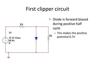
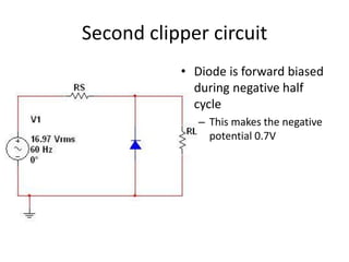
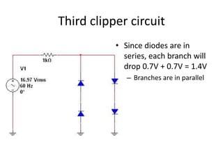
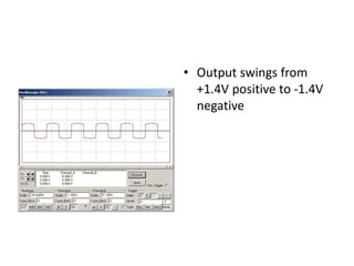
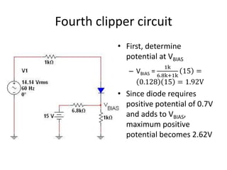
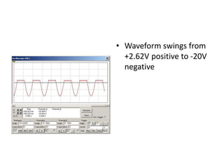
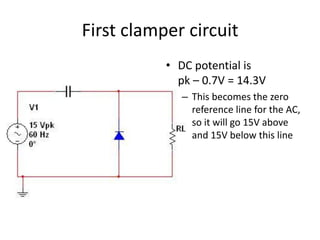
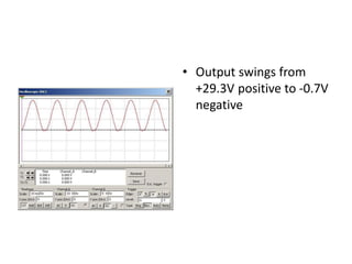
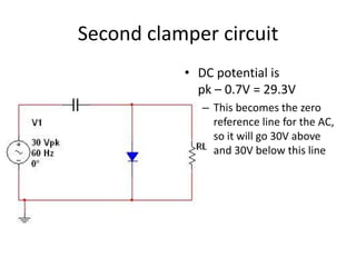
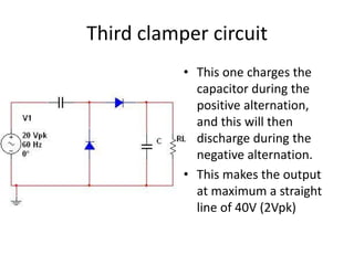
Diode circuits

Clippers and Clampers
First clipper circuit
           • Diode is forward biased
             during positive half
             cycle
              – This makes the positive
                potential 0.7V
• Output swings from
  0.7V positive to -50V
  negative
Second clipper circuit
           • Diode is forward biased
             during negative half
             cycle
              – This makes the negative
                potential 0.7V
• Output swings from
  +24V positive to -0.7V
  negative
Third clipper circuit
           • Since diodes are in
             series, each branch will
             drop 0.7V + 0.7V = 1.4V
              – Branches are in parallel
• Output swings from
  +1.4V positive to -1.4V
  negative
Fourth clipper circuit
           • First, determine
             potential at VBIAS
                         1k
              – VBIAS =    15 =
                      6.8k+1k
                 0.128 15 = 1.92V
           • Since diode requires
             positive potential of 0.7V
             and adds to VBIAS,
             maximum positive
             potential becomes 2.62V
• Waveform swings from
  +2.62V positive to -20V
  negative
First clamper circuit
           • DC potential is
             pk – 0.7V = 14.3V
              – This becomes the zero
                reference line for the AC,
                so it will go 15V above
                and 15V below this line
• Output swings from
  +29.3V positive to -0.7V
  negative
Second clamper circuit
           • DC potential is
             pk – 0.7V = 29.3V
              – This becomes the zero
                reference line for the AC,
                so it will go 30V above
                and 30V below this line
• Output swings from
  +0.7V positive to -59.3V
  negative
Third clamper circuit
           • This one charges the
             capacitor during the
             positive alternation,
             and this will then
             discharge during the
             negative alternation.
           • This makes the output
             at maximum a straight
             line of 40V (2Vpk)
• However, since the diode is not perfect we
  need to use the first approximation (simplified
  diode)
  – This means we need to subtract 0.7V for the one
    diode that charges the capacitor (39.3V)
  – And lest we forget, subtract the potential for the
    second diode as well (38.6V)
• Output is pulsating
  wave (ripple) that rises
  to a maximum potential
  of 39.3V and descends
  to a minimum potential
  of 38.6V
Diode clipper-and-clampers-lecture

Diode clipper-and-clampers-lecture

  • 1.
  • 2.
    First clipper circuit • Diode is forward biased during positive half cycle – This makes the positive potential 0.7V
  • 3.
    • Output swingsfrom 0.7V positive to -50V negative
  • 4.
    Second clipper circuit • Diode is forward biased during negative half cycle – This makes the negative potential 0.7V
  • 5.
    • Output swingsfrom +24V positive to -0.7V negative
  • 6.
    Third clipper circuit • Since diodes are in series, each branch will drop 0.7V + 0.7V = 1.4V – Branches are in parallel
  • 7.
    • Output swingsfrom +1.4V positive to -1.4V negative
  • 8.
    Fourth clipper circuit • First, determine potential at VBIAS 1k – VBIAS = 15 = 6.8k+1k 0.128 15 = 1.92V • Since diode requires positive potential of 0.7V and adds to VBIAS, maximum positive potential becomes 2.62V
  • 9.
    • Waveform swingsfrom +2.62V positive to -20V negative
  • 10.
    First clamper circuit • DC potential is pk – 0.7V = 14.3V – This becomes the zero reference line for the AC, so it will go 15V above and 15V below this line
  • 11.
    • Output swingsfrom +29.3V positive to -0.7V negative
  • 12.
    Second clamper circuit • DC potential is pk – 0.7V = 29.3V – This becomes the zero reference line for the AC, so it will go 30V above and 30V below this line
  • 13.
    • Output swingsfrom +0.7V positive to -59.3V negative
  • 14.
    Third clamper circuit • This one charges the capacitor during the positive alternation, and this will then discharge during the negative alternation. • This makes the output at maximum a straight line of 40V (2Vpk)
  • 15.
    • However, sincethe diode is not perfect we need to use the first approximation (simplified diode) – This means we need to subtract 0.7V for the one diode that charges the capacitor (39.3V) – And lest we forget, subtract the potential for the second diode as well (38.6V)
  • 16.
    • Output ispulsating wave (ripple) that rises to a maximum potential of 39.3V and descends to a minimum potential of 38.6V