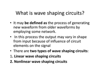
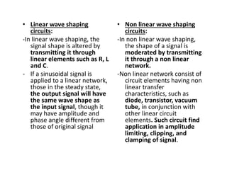
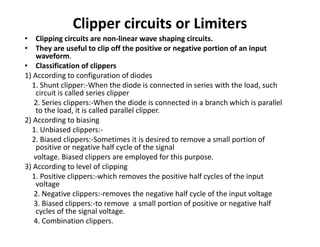
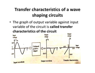
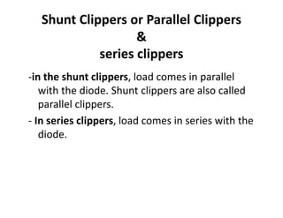
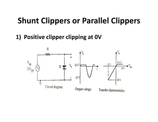
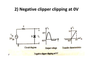
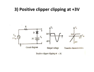
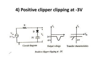
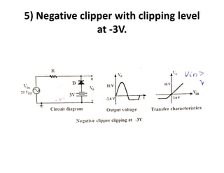
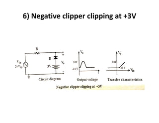
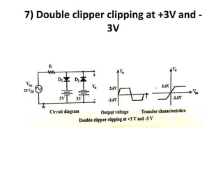
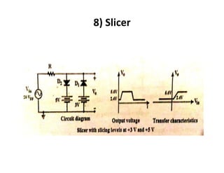
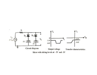
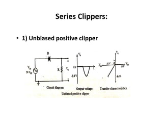
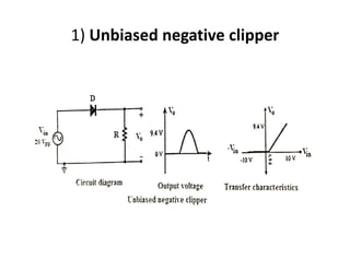
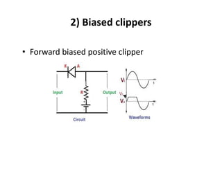
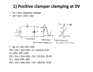
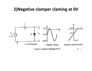
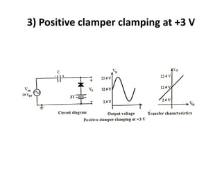
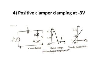
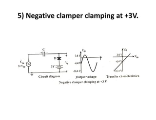
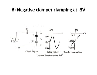
WAVE SHAPING CIRCUITS
What is wave shaping circuits?
• It may be defined as the process of generating
new waveform from older waveforms by
employing some network.
• In this process the output may vary in shape
from input because of influence of circuit
elements on the signal
• There are two types of wave shaping circuits:
1. Linear wave shaping circuits
2. Nonlinear wave shaping circuits
• Linear wave shaping
circuits:
-In linear wave shaping, the
signal shape is altered by
transmitting it through
linear elements such as R, L
and C.
- If a sinusoidal signal is
applied to a linear network,
those in the steady state,
the output signal will have
the same wave shape as
the input signal, though it
may have amplitude and
phase angle different from
those of original signal
• Non linear wave shaping
circuits:
-In non linear wave shaping,
the shape of a signal is
moderated by transmitting
it through a non linear
network.
-Non linear network consist of
circuit elements having non
linear transfer
characteristics, such as
diode, transistor, vacuum
tube, in conjunction with
other linear circuit
elements. Such circuit find
application in amplitude
limiting, clipping, and
clamping of signal.
Clipper circuits or Limiters
• Clipping circuits are non-linear wave shaping circuits.
• They are useful to clip off the positive or negative portion of an input
waveform.
• Classification of clippers
1) According to configuration of diodes
1. Shunt clipper:-When the diode is connected in series with the load, such
circuit is called series clipper
2. Series clippers:-When the diode is connected in a branch which is parallel
to the load, it is called parallel clipper.
2) According to biasing
1. Unbiased clippers:-
2. Biased clippers:-Sometimes it is desired to remove a small portion of
positive or negative half cycle of the signal
voltage. Biased clippers are employed for this purpose.
3) According to level of clipping
1. Positive clippers:-which removes the positive half cycles of the input
voltage
2. Negative clippers:-removes the negative half cycle of the input voltage
3. Biased clippers:-to remove a small portion of positive or negative half
cycles of the signal voltage.
4. Combination clippers.
Transfer characteristics of a wave
shaping circuits
• The graph of output variable against input
variable of the circuit is called transfer
characteristics of the circuit
Shunt Clippers or Parallel Clippers
&
series clippers
-in the shunt clippers, load comes in parallel
with the diode. Shunt clippers are also called
parallel clippers.
- In series clippers, load comes in series with the
diode.
Shunt Clippers or Parallel Clippers
1) Positive clipper clipping at 0V
2) Negative clipper clipping at 0V
3) Positive clipper clipping at +3V
4) Positive clipper clipping at -3V
5) Negative clipper with clipping level
at -3V.
6) Negative clipper clipping at +3V
7) Double clipper clipping at +3V and -
3V
8) Slicer
Series Clippers:
• 1) Unbiased positive clipper
1) Unbiased negative clipper
2) Biased clippers
• Forward biased positive clipper
Clamping circuits
• In some situations it is necessary to add or subtract a
dc voltage to a given waveform without changing its
shape.Circuits used for this purpose are called
clamping circuits
or
• A circuit that places either the positive or negative
peak of a signal at a desired DC level is known as a
clamping circuit
1) Positive clamper clamping at 0V
• Vo = Vin+ capacitor voltage
• V0 = Vin + (Vm –VD)
• Eg: Vi = 0V; VPP =20V
VO = Vin + (Vm-VD) = 0 + 10-0.6= 9.4V
Vi =10V; VPP =20V
VO = Vin + (Vm-VD) = 10 + 10-0.6= 19.4V
Vi = -10V; VPP =20V
VO = Vin + (Vm-VD) =-10 + 10-0.6= -0.6V
2)Negative clamper claming at 0V
3) Positive clamper clamping at +3 V
4) Positive clamper clamping at -3V
5) Negative clamper clamping at +3V.
6) Negative clamper clamping at -3V
Applications of Clippers and Clampers
• Clippers find several applications, such as
• · They are frequently used for the separation of synchronizing
signals from the composite picture signals.
• · The excessive noise spikes above a certain level can be limited or
clipped in FM transmitters by using the series clippers.
• · For the generation of new waveforms or shaping the existing
waveform, clippers are used.
• · The typical application of diode clipper is for the protection of
transistor from transients, as a freewheeling diode connected in
parallel across the inductive load.
• · Frequently used half wave rectifier in power supply kits is a typical
example of a clipper. It clips either positive or negative half wave of
the input.
• · Clippers can be used as voltage limiters and amplitude selectors.
• Clampers can be used in applications
• · The complex transmitter and receiver circuitry of television
clamper is used as a base line stabilizer to define sections of the
luminance signals to preset levels.
• · Clampers are also called as direct current restorers as they clamp
the wave forms to a fixed DC potential.
• · These are frequently used in test equipment, sonar and radar
systems.
• · For the protection of the amplifiers from large errant signals
clampers are used.
• · Clampers can be used for removing the distortions.
• · For improving the overdrive recovery time clampers are used.
• · Clampers can be used as voltage doublers or voltage multipliers
ZENER DIODE SHUNT REGULATOR
(VOLATGE REGULATOR )-design
• Advantages of Zener voltage regulation
• 1) They are smaller 2) Simpler 3) cheaper 4)
Lighter 5) More rugged 6) Longer life
Disadvantages:
• 1) Efficiency is low for heavy load current because
there is a considerable power loss in series
resistor RS and diode 2) The output voltage varies
slightly due to Zener impedance 3) The output
voltage cannot be chosen independently but
depends upon the breakdown voltage of the
zener diode
clipping and clamping.pdf

clipping and clamping.pdf

  • 1.
  • 2.
    What is waveshaping circuits? • It may be defined as the process of generating new waveform from older waveforms by employing some network. • In this process the output may vary in shape from input because of influence of circuit elements on the signal • There are two types of wave shaping circuits: 1. Linear wave shaping circuits 2. Nonlinear wave shaping circuits
  • 3.
    • Linear waveshaping circuits: -In linear wave shaping, the signal shape is altered by transmitting it through linear elements such as R, L and C. - If a sinusoidal signal is applied to a linear network, those in the steady state, the output signal will have the same wave shape as the input signal, though it may have amplitude and phase angle different from those of original signal • Non linear wave shaping circuits: -In non linear wave shaping, the shape of a signal is moderated by transmitting it through a non linear network. -Non linear network consist of circuit elements having non linear transfer characteristics, such as diode, transistor, vacuum tube, in conjunction with other linear circuit elements. Such circuit find application in amplitude limiting, clipping, and clamping of signal.
  • 4.
    Clipper circuits orLimiters • Clipping circuits are non-linear wave shaping circuits. • They are useful to clip off the positive or negative portion of an input waveform. • Classification of clippers 1) According to configuration of diodes 1. Shunt clipper:-When the diode is connected in series with the load, such circuit is called series clipper 2. Series clippers:-When the diode is connected in a branch which is parallel to the load, it is called parallel clipper. 2) According to biasing 1. Unbiased clippers:- 2. Biased clippers:-Sometimes it is desired to remove a small portion of positive or negative half cycle of the signal voltage. Biased clippers are employed for this purpose. 3) According to level of clipping 1. Positive clippers:-which removes the positive half cycles of the input voltage 2. Negative clippers:-removes the negative half cycle of the input voltage 3. Biased clippers:-to remove a small portion of positive or negative half cycles of the signal voltage. 4. Combination clippers.
  • 5.
    Transfer characteristics ofa wave shaping circuits • The graph of output variable against input variable of the circuit is called transfer characteristics of the circuit
  • 6.
    Shunt Clippers orParallel Clippers & series clippers -in the shunt clippers, load comes in parallel with the diode. Shunt clippers are also called parallel clippers. - In series clippers, load comes in series with the diode.
  • 7.
    Shunt Clippers orParallel Clippers 1) Positive clipper clipping at 0V
  • 8.
    2) Negative clipperclipping at 0V
  • 9.
    3) Positive clipperclipping at +3V
  • 10.
    4) Positive clipperclipping at -3V
  • 11.
    5) Negative clipperwith clipping level at -3V.
  • 12.
    6) Negative clipperclipping at +3V
  • 13.
    7) Double clipperclipping at +3V and - 3V
  • 14.
  • 16.
    Series Clippers: • 1)Unbiased positive clipper
  • 17.
  • 18.
    2) Biased clippers •Forward biased positive clipper
  • 19.
    Clamping circuits • Insome situations it is necessary to add or subtract a dc voltage to a given waveform without changing its shape.Circuits used for this purpose are called clamping circuits or • A circuit that places either the positive or negative peak of a signal at a desired DC level is known as a clamping circuit
  • 20.
    1) Positive clamperclamping at 0V • Vo = Vin+ capacitor voltage • V0 = Vin + (Vm –VD) • Eg: Vi = 0V; VPP =20V VO = Vin + (Vm-VD) = 0 + 10-0.6= 9.4V Vi =10V; VPP =20V VO = Vin + (Vm-VD) = 10 + 10-0.6= 19.4V Vi = -10V; VPP =20V VO = Vin + (Vm-VD) =-10 + 10-0.6= -0.6V
  • 21.
  • 22.
    3) Positive clamperclamping at +3 V
  • 23.
    4) Positive clamperclamping at -3V
  • 24.
    5) Negative clamperclamping at +3V.
  • 25.
    6) Negative clamperclamping at -3V
  • 26.
    Applications of Clippersand Clampers • Clippers find several applications, such as • · They are frequently used for the separation of synchronizing signals from the composite picture signals. • · The excessive noise spikes above a certain level can be limited or clipped in FM transmitters by using the series clippers. • · For the generation of new waveforms or shaping the existing waveform, clippers are used. • · The typical application of diode clipper is for the protection of transistor from transients, as a freewheeling diode connected in parallel across the inductive load. • · Frequently used half wave rectifier in power supply kits is a typical example of a clipper. It clips either positive or negative half wave of the input. • · Clippers can be used as voltage limiters and amplitude selectors.
  • 27.
    • Clampers canbe used in applications • · The complex transmitter and receiver circuitry of television clamper is used as a base line stabilizer to define sections of the luminance signals to preset levels. • · Clampers are also called as direct current restorers as they clamp the wave forms to a fixed DC potential. • · These are frequently used in test equipment, sonar and radar systems. • · For the protection of the amplifiers from large errant signals clampers are used. • · Clampers can be used for removing the distortions. • · For improving the overdrive recovery time clampers are used. • · Clampers can be used as voltage doublers or voltage multipliers
  • 28.
    ZENER DIODE SHUNTREGULATOR (VOLATGE REGULATOR )-design
  • 29.
    • Advantages ofZener voltage regulation • 1) They are smaller 2) Simpler 3) cheaper 4) Lighter 5) More rugged 6) Longer life Disadvantages: • 1) Efficiency is low for heavy load current because there is a considerable power loss in series resistor RS and diode 2) The output voltage varies slightly due to Zener impedance 3) The output voltage cannot be chosen independently but depends upon the breakdown voltage of the zener diode